antenna ACURA INTEGRA 1998 Service Repair Manual
[x] Cancel search | Manufacturer: ACURA, Model Year: 1998, Model line: INTEGRA, Model: ACURA INTEGRA 1998Pages: 1680, PDF Size: 53.14 MB
Page 948 of 1680

Dashboard
Component Removal/lnstallation (cont'dl
5. Remove the knee bolster.
: Bolt
A'ir
locations,3
6 x 1.0 mm9.8 N.m
{1.0 kgt m,7.2 tbf.fit
0
6. lnstallation is the reverse o{ the removal procedure.
Ste.eo ladio/cassette, Heatet contlol Danel removal:
1. Remove the rear console, then remove the front
console (see page 20-130).
Loosen the bolts, then remove the stereo radio/
cassette by pulling it out.
Disconnect the connector and antenna lead.
NOTEr The original radio has a coded theft protec-
tion circuit. Be sure to get the customer's code num-
ber before- disconnecting the battery.- removing the No. 47 (7.5 A) tuse from the under-
hood fuse/relay box.- removing the radio,
After service, reconnect power to the radio and turn
it on. When the word "CODE" is displayed, enter
the customer's 5-digit code to restore radio
ope.ation.
KNEE BOLSTER
20-134
CONNECTOR
CASSETTE
: Bolt locations, 2
6x1.0mm9.8 N.m {1.0 kgt m,
3. Carefully pry the hazard warning switch and rear
window detogger switch out of the heater control
panel.
Disconnect the connectors.
HAZARD WARNINGswtTcHREAR WINDOWDEFOGGER SWITCH
CONNECTORS
Page 954 of 1680

Dashboard
6.
Replacement (cont'dl
5. Disconnect the antenna lead.
Disconnect the connectors from the under-dash
fuse/relay box.
7.Remove the access panels on both sides.
CAUTION: When pfying with a tlat tip screwdrivel,
wrap it with protective tape to prevent damage.
ACCESSPANEL
HOOK H R<-- cLlP -- tfit\z-:E--4l_l
L__\L
lccPss pltlteL /
DASHBOARD
20-140
8. Remove the bolts, then lift and remove the
dashboard.
CAUTION: Use protective tape on the bottom of thefront pillar trim.
NOTE:
a Take care not to scratch the dashboard.
a To prevent damage to the shift lever and A/T gear
position indicator panel, wrap them with a shop
rowet.
V: Eolt localions, 6
6 x 1.0 mm9.8 N.m {1.0 kgf m,7 .2 ,hl.ltl
9. Installation is the reverse of the removal procedure.
NOTE:
a Make sure the dashboard fits onto the body cor,rec y.
a Before tightening the bolts, make sure the dashboard wire harnesses are not pinched, and that
the dashboard is not interfering with the air mix
control cable.
SHOP TOWEL
Page 1058 of 1680
![ACURA INTEGRA 1998 Service Repair Manual SpecialTools
\
Ref. No. J Tool NumbelDescliptionOty Page Reference
o-
o
\9-]
@
o
E
o
@
o
@-
07HAz - SG00400
07JAA - 001000c
07JGG - 001010A
OTLAJ _ PT3O2OA
07NAC - SR20100
07PAZ - 0010100
07sAz - TB4 ACURA INTEGRA 1998 Service Repair Manual SpecialTools
\
Ref. No. J Tool NumbelDescliptionOty Page Reference
o-
o
\9-]
@
o
E
o
@
o
@-
07HAz - SG00400
07JAA - 001000c
07JGG - 001010A
OTLAJ _ PT3O2OA
07NAC - SR20100
07PAZ - 0010100
07sAz - TB4](/img/32/56983/w960_56983-1057.png)
SpecialTools
\
Ref. No. J Tool NumbelDescliptionOty Page Reference
o-
o
\9-]
@
o
E'
o
@
o
@-
07HAz - SG00400
07JAA - 001000c
07JGG - 001010A
OTLAJ _ PT3O2OA
07NAC - SR20100
07PAZ - 0010100
07sAz - TB4011A
07TAZ - SZ5011A
07r Az - s250200
07TM - 001020A
Deployment Tool
Antenna Nut Wrench
Belt Tension Gauge
Test Harness
Fuel Sender Wrench
SCS Service Connector
SRS Inflator Simulator
SRS Simulator Lead C
SCS Service Connector (2 o)
Backprobe Adapter, l7 mm
1,|
1
1
1
1
1'l
1
2
23-320
23-203
23-1't5
23-124
23-90,288
23-301
23-30'l
23-301
23-287
*r: lncluded in SRS Tool Set 07MAz - SM5000B*,: Use with the staking patch cords from T/N 07SM 0010004, Backprobe Set.
o
o
@@
23-2
Page 1084 of 1680
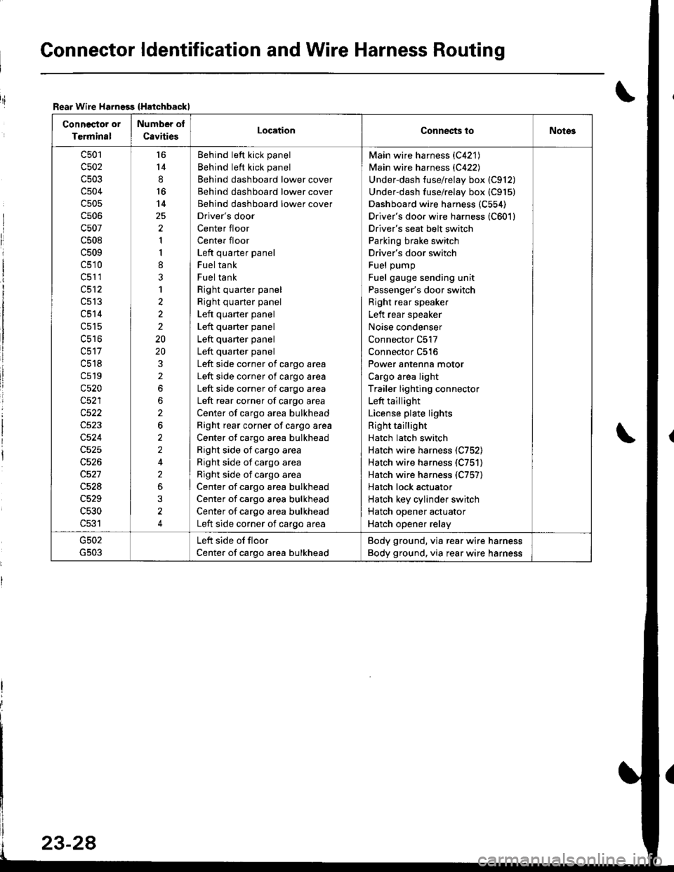
Gonnector ldentification and Wire Harness Routing
Rear Wire Harngss {Hatchbackl
Connector or
Terminal
Number of
C8vitiesLocationConnec{s toNotos
c501
c502
c504
c505
cs06
c507
c508
c509
c510
c51 1
c512
c513
c514
c515
uc to
c518
c519
c520
c522
c524
c528
c529
c530
c531
l6
14
8
16
14
2
1
I
8
3
1
2
2
2
20
20
2
2
6
2
2
2
3
4
Behind left kick panel
Behind left kick panel
Behind dashboard lower cover
Behind dashboard lower cover
Behind dashboard lower cover
Driver's door
Center floor
Center floor
Left quarter panel
Fuel tank
Fuel tank
Right quarter panel
Right quarter panel
Left quarter panel
Left quarter panel
Left quaner panel
Left quarter panel
Left side corner of cargo area
Left side corner of cargo area
Left side corner of cargo area
Left rear corner of cargo area
Center of cargo area bulkhead
Right rear corner of cargo area
Center of cargo area bulkhead
Right side of cargo area
Right side of cargo area
Right side of cargo area
Center of cargo area bulkhead
Center of cargo area bulkhead
Center of cargo area bulkhead
Left side corner of cargo area
Main wire harness {C421)
Main wire harness {C422)
Underdash fuse/relay box (C912)
Underdash fuse/relay box (C915)
Dashboard wire harness (C554)
Driver's doo. wire harness (C601)
Driver's seat belt switch
Parking brake switch
Driver's door switch
Fuel pump
Fuel gauge sending unit
Passenger's door switch
Right rear speaker
Left rear speaker
Noise condenser
Connector C517
Connector C516
Power antenna motor
Cargo area light
Trailer lighting connector
Left taillight
License plate lights
Right taillight
Hatch latch switch
Hatch wire harness (C752)
Hatch wire harness (C751)
Hatch wire harness (C757)
Hatch lock actuator
Hatch key cylinder switch
Hatch opener actuator
Hatch opener relay
Left side of floor
Center of cargo area bulkhead
Body ground, via rear wire harness
Body ground. via rear wire harness
riI
Page 1086 of 1680
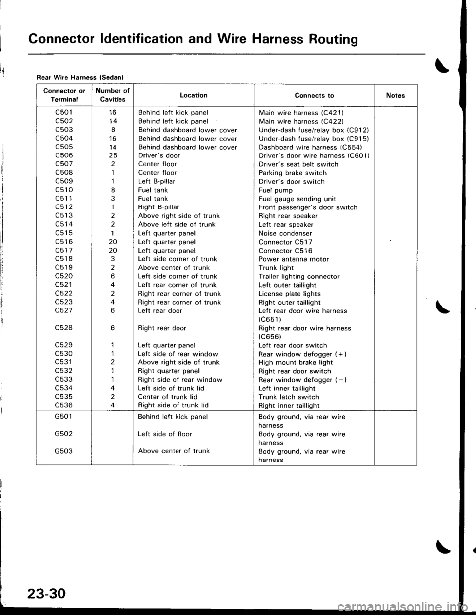
Connector ldentification and Wire Harness Routing
Connector or
Terminal
Numbel of
CavitiesLocationConnects toNotes
c501
c502
c503
c504
c505
c506
c507
c508
c509
c5l0
c511
c512
c513
c514
c515
c517
c518
c519
c520
c521
c522
c523
c527
c528
c529
c530
c531
c532
c533
c534
c535
cs36
14
8
14
2
1
1
8
3
1
2
2
1
20
20
3
2
6
4
2
4
6
6
1
1
2
1
1
4
2
4
Behind left kick panel
Behind left kick panel
Behind dashboard lower cover
Behind dashboard lower cover
Behind dashboard lower cover
Driver's door
Center floor
Center floor
Left B-pillar
Fuel tank
Fuel tank
Right B pillar
Above right side of trunk
Above left side of trunk
Left quarter panel| .{+ ^',rrrar ^rnal
Left quarter panel
Left side corner of trunk
Above center of trunk
Left side corner of trunk
Left rear corner of trunk
Right rear corner o{ trunk
Right rear corner ot trunk
Lelt rear door
Right rear door
Left quarter panel
Left side of rear window
Above right side of trunk
Right quarter panel
Right side of rear window
Left side of trunk lid
Center of trunk lid
Right side of trunk lid
lvlain wire harness (C421 )
lvlain wire harness (C422)
Underdash fuse/relay box (C912)
Under dash fuse/relay box (C915)
Dashboard wire harness (C554)
Driver's door wire harness (C6Ol)
Driver's seat belt switch
Parking brake switch
Driver's door switch
Fuel pump
Fuel gauge sending unit
Front passenger's door switch
Right rear speaker
Left rear speaker
Noise condenser
Connector C517
Connector C516
Power antenna motor
Trunk light
Trailer lighting connector
Left outer taillight
License plate lights
Right outer taillight
Lett rear door wire harness
(c651)
Right rear door wire harness
1C656)
Left rear door switch
Rear window defogger {+ )
High mount brake light
Right rear door switch
Rear window detogger (- I
Left inner taillight
Trunk latch switch
Right inner taillight
G501
G502
G503
Behind left kick panel
Left side of tloor
Above center of trunk
Body ground, via rear wire
harness
Body ground, via rear wire
harness
Body ground, via rear wire
harness
Rear Wire Hamess {Sedan}
I
ri
I
i
I
li
!
Page 1109 of 1680

J
)1 -
Fuso NumborAmpsWir€ ColorComponent(s) or Circuh(rl Protastcd
41100 ABattery. power distribution
4240AWHT/BLKlgnition switch (BAT)
437.5 AWHT/REDCeiling light, cargo area light, data link connector (DLCl, power
antenna connector
44't5 AYEL/WHTPGM-Fl main relay
45Not used
4640AWHT/8LU
No. 7 (20 A) fuse (Via power window relay), No. 8 (20 A) tuse (Via
power window relay)
No. 10 (20 A) fuse (Via power window relay), No. 11 (20 A) fuse (Via
power window relay)
417.5 AWHT/BLUClock,8udio unit connector, ECM, TCM, Maint€nance reminder unit
4840AWHTCombination light switch (Headlight)
4930AWHT/BLUMoonroof relay
5040AWHT/GRNRear window defogger {Via rear window defogger relay)
51154WHTCombination light switch (Dash lights)
20AWHT/GRNHorn, horn relay, brake lights, AgS control unit, ECM, TCM
10AWHT/GRNTurn signal/hazard relay, hazard warning light
5440AWHT/flEDNo. 1 (20 A) fuse
40ABLU/WHTBlower motor (Via blower motor relsy)
56204BLU/BLKCondenser fan motor (Via condenser {an motor relay)
REDA,/C compressor clutch (via Ay'c comp.essor clutch relay)
57204BLVREDRadiator f8n motor (Via radiator fan relay)
23-53
Page 1115 of 1680
![ACURA INTEGRA 1998 Service Repair Manual i4l:
iL
BLU/BLK + ftrtltt *r*,r.,
8LlffiED
T
BLK/]I/HT - Shnsrsolenoid
BLKWHT - Slanorsolenoid
lPi[ 8i:tJl.,i (")
V
J--
; 8LK,,r,vHT STAFTEF| | cUT RELAY
tt+
tttil
i l_L i-l_
I l==_ |
ii?;19$dl ACURA INTEGRA 1998 Service Repair Manual i4l:
iL
BLU/BLK + ftrtltt *r*,r.,
8LlffiED
T
BLK/]I/HT - Shnsrsolenoid
BLKWHT - Slanorsolenoid
lPi[ 8i:tJl.,i (")
V
J--
; 8LK,,r,vHT STAFTEF| | cUT RELAY
tt+
tttil
i l_L i-l_
I l==_ |
ii?;19$dl](/img/32/56983/w960_56983-1114.png)
i'4l:
iL
BLU/BLK + ft'rtltt *r*,r.,
8LlffiED
T
BLK/]'I/HT - Shnsrsolenoid
BLKWHT - Slanorsolenoid
lPi[ 8i:t'Jl.,i (")
V
J--
; 8LK,,r,vHT STAFTEF| | cUT RELAY
tt+
tttil
i l_L i-l_
I l==_ |
ii?;19$'dlYi6 F-
Inlegraled control unil
ECMPGM'FImain relay
Key inlerlock solenoid (A/T)lnteiock conlrol un 1 (fuT)
COMSINAT]ON LIGHT SWITCH(To page 23 60)N0.43(Fom
Dara inh conneclof (olc)- C€ilinq liqhl
Cargo area lighl- Power antenna molof conneclor
(cont'd)
23-59
BLIffiED
UNDER.DASH FUSE/FEtAY 8OX
(Fuse/@lay box soc*el)
(7.54)FUSEpage 23'54)
f.7
I
N0.31 (7 5A)--l
N0.33 (7.54)
stuMHT-
I_
N0.20 (Nolused)
L
I_
Page 1252 of 1680
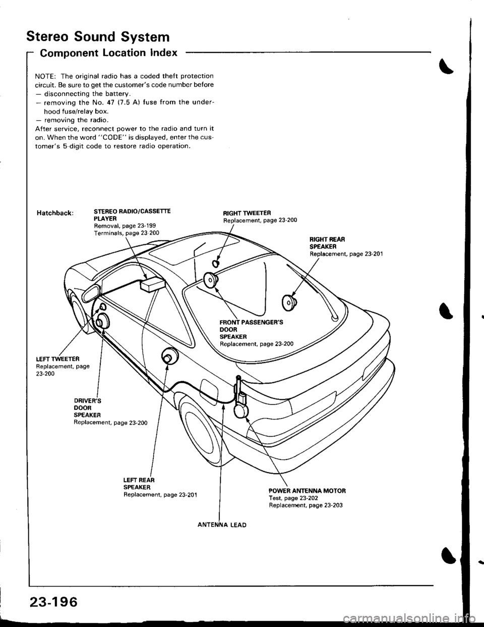
Stereo Sound System
Component Location Index
DOORSPEAKERReplacement, page 23-2OO
NOTE: The original radio has a coded theft protection
circuit. Be sure to get the customer's code number betore- disconnecting the battery.- removing the No.47 (7.5 A) fuse from the under-
hood fuse/relay box.- removing the radio.
After service, reconnect power to the radio and turn it
on. When the word "CODE" is displayed, enter the cus-
tomer's 5 digit code to restore radio operation.
STEREO RADIO/CASSETTEPLAYERRemoval, page 23-199Terminals, page 23 200
RIGHT TWEETERReplacement, page 23'200
BIGHT REARSPEAKERReplacement, page 23-201
LEFT REARSPEAKERReplacement, page 23,201POWER ANTENNA MOTORTest, page 23-202Replacernent, page 23-203
23-196
Page 1253 of 1680
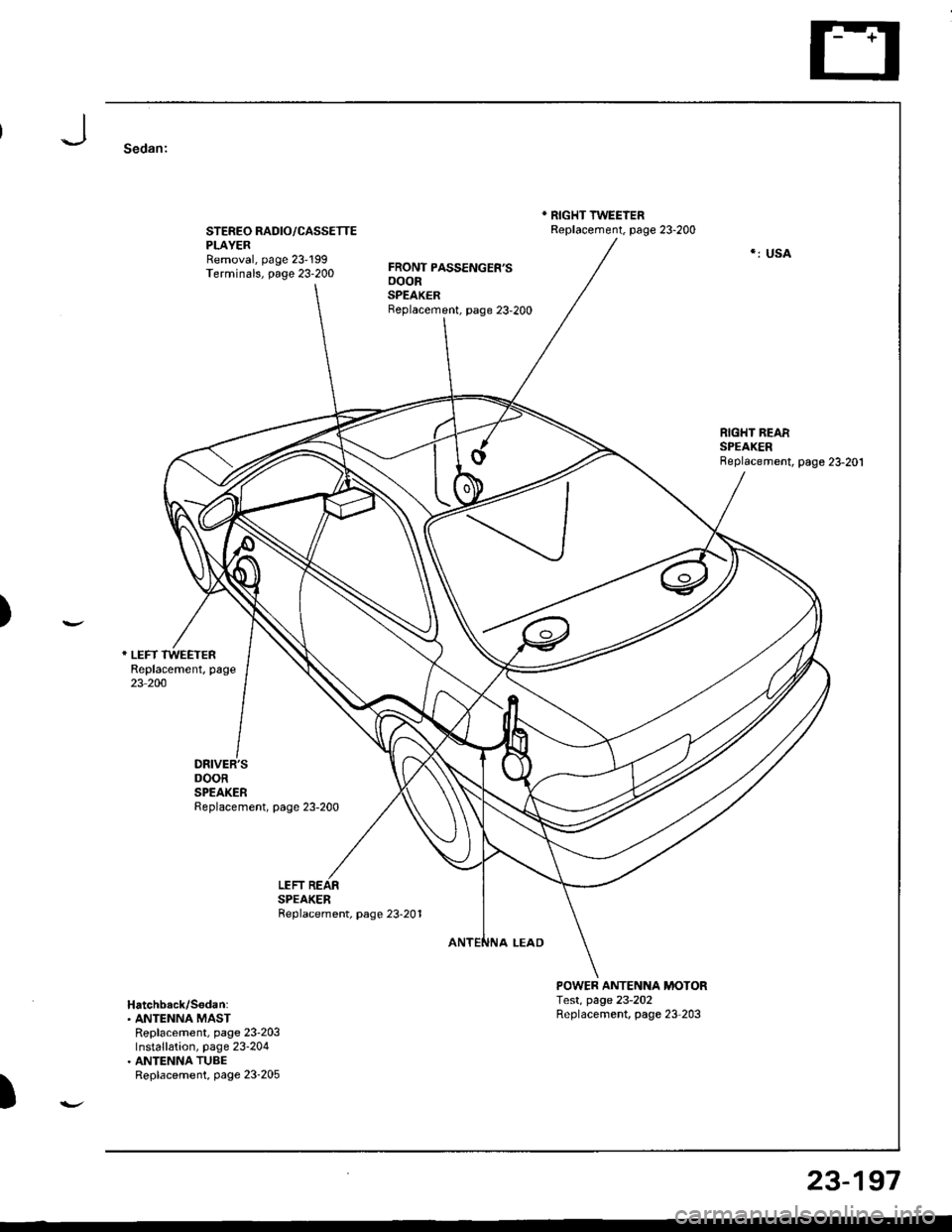
Sedan:
STEREO RADIO/CASSETTEPLAYERRemoval, page 23'199Terminals, page 23-200
DRIVER'SDOORSPEAKERReplacement, page 23-200
FRONT PASSENGER'SooonSPEAKERBeplacement, page 23-200
* RIGHT TWEEIERReplacement. page 23-200
POWER ANTENNA MOTORTest, page 23-202Replacement, page 23-203
*: USA
)
LEFTSPEAKERReplacement, page 23-201
Hatchback/S6dan:. ANTENNA MASTReplacement, page 23'203Installation, page 23-204. ANTENNA TUBEReplacement, page 23-205
)
23-197
Page 1254 of 1680
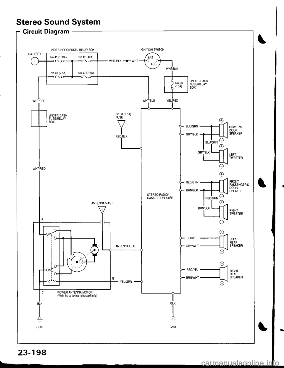
Stereo Sound System
Circuit Diagram
WHT/RED
tWHTi RED
UNDER.HOOD FUSE / RELAY BOX
UNDER.DASHFUSE/RELAYBOX
N0.30 (7.5A)FUSE
f7
IRED/BLK
UNDER,DASHFUSE/RELAYBOX
FRONTPASSENGER'SoooRSPEAKER
ANTENNA MAST
LEFTREABSPEAKER
RIGHTREARSPEAKEB
rna-ll
-ttl
;\\:/
o=4-ll
-{tl
x!\:/
ANTENNA LEAD
BLU,YEL
GRY/rrVHT
REO/YEL
ERNMHT
POWER ANTENNA MOTOR{wilh lhe antenna reraded lully)
BLK
I
G551
8LK
I
G503
No 4l (100A) No 42 (40A)
rc\RED/GRN VSTEBEO RADIOiCASSETTE PLAYER
23-198