c301 ACURA INTEGRA 1998 Service Repair Manual
[x] Cancel search | Manufacturer: ACURA, Model Year: 1998, Model line: INTEGRA, Model: ACURA INTEGRA 1998Pages: 1680, PDF Size: 53.14 MB
Page 1069 of 1680

Connector ldentification and Wire Harness Routing
JHow to ldenti{v Connectors:
ldentification numbers have been assigned to all connectors. The number is preceded by the letter "C" for connectors,"G" for single ground terminals ot "f" lor single non-ground terminals.
/
Location
HarnossEngine CompartmentDashboardOthers (Floor, Door,
Trunk. Rooll
Starter cablesT1, T2, and @
Battery ground cableG1 and O
Engine ground cable A
G2
Engine ground cable BT4
G3
Under-hood ABS fuse/relav box cableT5 and @
Engine wire harnessC101 through C134
T101 and T102
G101
A,/C wire harnessC151 through C156
G151
Engine compartment wire harnessC301 through C320
G301
Main wire harnessC201 through C223
G20'l and G202
C40l through C454
G401
Rear wire harnessC501 through C536
G501 (Sedan), G502
and G503
Dashboard wire harnessC551 through C569
G551
Driver's door wire harnessC601 through C612
Front passenger's door wire harnessC626 through C634
Left rear door wire harness (Sedan)C65l through C654
Right rear door wire harness (SedanlC656 throughc659
Roof wire harnessC661 through C667
Heater sub-harness AC671 through C677
Heater sub-harness BC68l through C684
ABS sub-harnessC701 through C706
G701 and G702
Hatch wire harness (Hatchback)C751 through C758
Spoiler sub-harness {Hatchback)C761 through C763
Rear window defogger ground wire
(Hatchback)
c11 l
G77'l
SRS main harnessC801 through C808
G801
23-13
Page 1076 of 1680
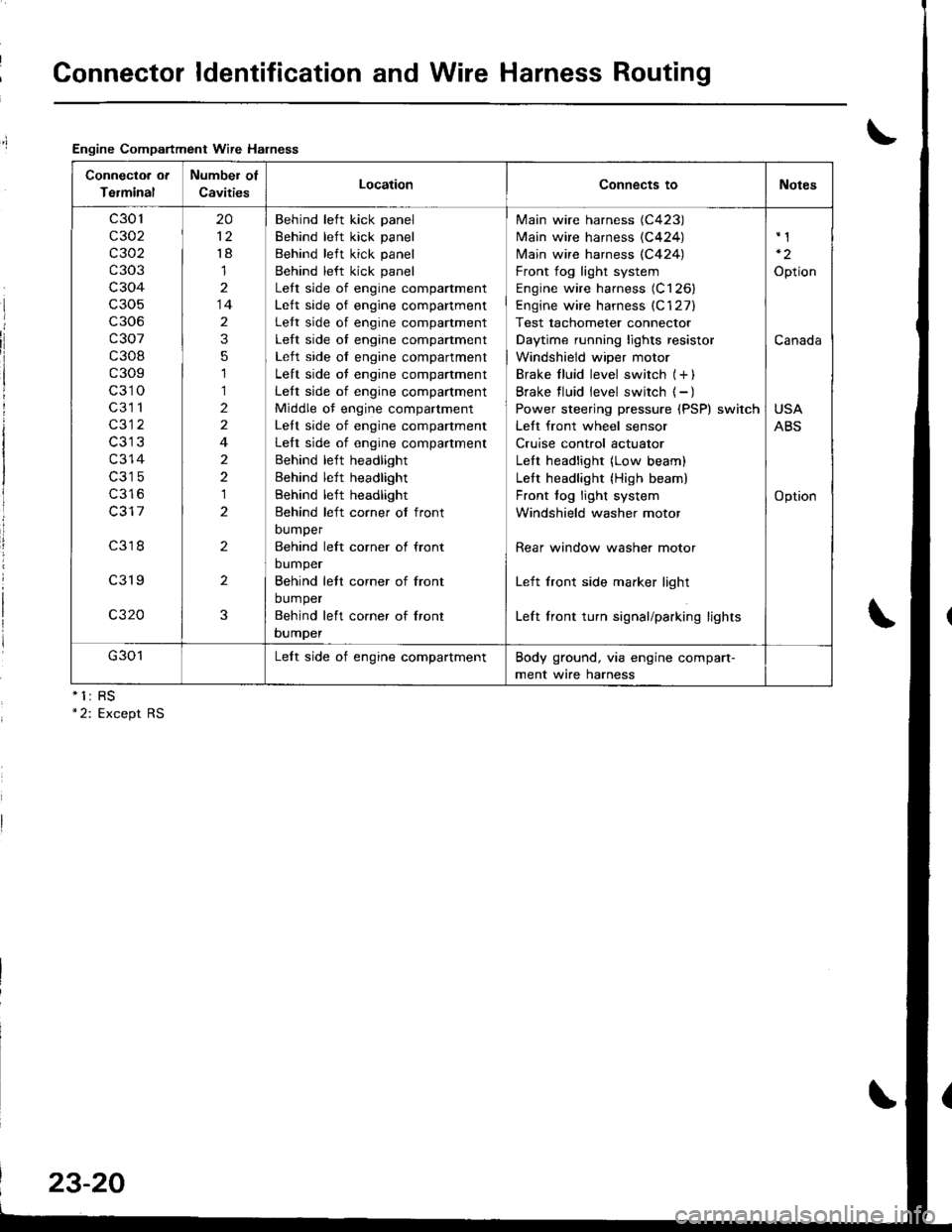
Connector ldentification and Wire Harness Routing
Engine Compartment Wire Halness
nll
Connectoa ot
Terminal
Number of
CavitiesLocationConnects toNotes
c301
c302
c 302
c303
c304
c306
c307
c308
c309
c310
c3l 1
c312
c314
c316
c317
c318
c319
c320
20
't8
1
14
2
3
5
1
1
2
2
4
2
2
1
2
2
2
3
Behind left kick panel
Behind left kick panel
Behind left kick panel
Behind left kick panel
Lett side of engine compartment
Lett side of engine companment
Lett side of engine compartment
Left side of engine compartment
Left side of engine compartment
Left side of engine compartment
Left side of engine compartment
Middle of engine compartment
Lett side of engine companment
Left side of engine compartment
Behind left headlight
Behind left headlight
Behind left headlight
Behind left corner of front
DUmper
Behind left corner ol front
bumper
Behind lett corner of front
bumper
Behind left co.ner of lront
bumper
Main wire harness (C423)
Main wire harness {C424)
N4ain wire harness (C424)
Front fog light system
Engine wire harness (C126)
Engine wire harness (C'127)
Test tachometer connector
Daytime running lights resistor
Windshield wiper motor
Brake f luid level switch (+ )
Brake f luid level switch ( - )
Power steering pressure (PSP) switch
Lett front wheel sensor
Cruise control actuator
LeIt headlight (Low beam)
Lett headlight {High beam)
Front fog light system
Windshield washer motor
Rear window washer motor
Left front side marker light
Left front turn signal/parking lights
Option
Canada
USA
ABS
Option
G301Lelt side of engine compartmentBody ground, via engine compart-
ment wire harness
23-20
Page 1082 of 1680
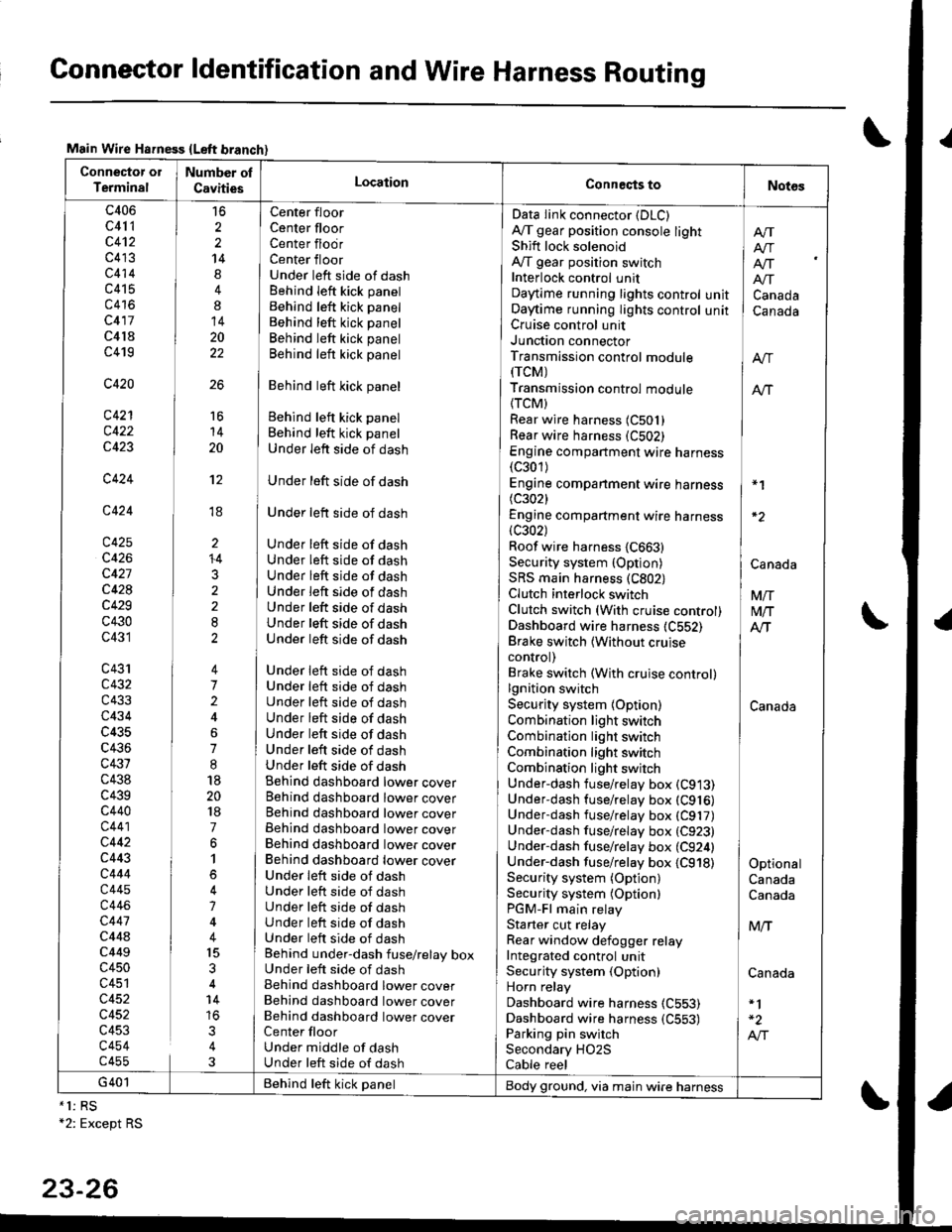
Connector ldentification and Wire Harness Routing
Main Wire Hsfness {Left branch}
Connector ol
TerminalNumber ol
CavitiesLocationConneqts toNot6s
c406
c41 1
c4't2
c413
c414
c415
c416
c417
c4l8
c419
c420
c421
c422
c423
c424
c424
c425
c426
c427
c428
c429
c430
c431
c43'rc432
c433
c434
c435
c436
c431
c438
c439c440
c441
c442
c443
c444
c445
c446
c447
c44ac449
c450
c451
c452
c452
c453
c454c455
16
2
2
14
4
8
14
20
22
26
Center floor
Center floorCenter flodrCenter floorUnder left side of dashBehind Ieft kick panel
Behind left kick panel
Behind left kick panel
Behind left kick panel
Behind left kick panel
Behind left kick panel
Behind left kick panel
Behind left kick panel
Under left side of dash
Under left side of dash
Under left side of dash
Under left side of dashUnder left side of dashUnder left side of dashUnder left side of dashUnder left side of dashUnder left side of dashUnder left side of dash
Under left side of dashUnder left side of dashUnder left side of dashUnder left side of dashUnder left side of dashUnder left side of dashUnder left side of dashBehind dashboard lower coverBehind dashboard lower coverBehind dashboard lower coverBehind dashboard lower coverBehind dashboard lower coverBehind dashboard lower coverUnder leit side of dashUnder left side of dashUnder left side of dashUnder left side of dashUnder left side of dashBehind under-dash fuse/relay boxUnder left side of dashBehind dashboard lower coverBehind dashboard lower coverBehind dashboard lower coverCenter floorUnder middle of dashUnder left side of dash
Data Iink connector (DLC)
A,/T gear position console lightShift lock solenoidAy'T gear position switchInterlock control unitDaytime running lights controlOaytime running lights controlCruise control unitJunction connectorTransmission control module(rcM)
Transmission control module
{TCM)Rear wire harness (C501)
Rear wire harness (C502)
Engine compartment wire harness(c301)
Engine companment wire harness I *1
(c3021 IEngine compartment wire harness(c302) lRoof wire harness {C663} |Security system {Option) | CanaAaSRS main harness (C802) |Clutch interlock switch I VnClutch switch (With cruise control) M/TDashboard wire harness (C552) AlTBrake switch lwithout cruise Icontrol) |Brake switch (With cruise control)lgnition switch ISecurity system {Option) CanadaCombination light switch /Combination light switch ICombination light switchCombination light switchUnder-dash fuse/relay box (C913)
Under-dash fuse/relay box (C916)
Underdash fuse/relay box (C917)
Under-dash fuse/relay box (C923)
Under-dash fuse/relay box (C924) |Under-dash fuse/relay box {C918) I OptionalSecurity system (Option) CanadaSecurity system (Optionl CanadaPGM-Fl main relayStarter cut relay ] M,.fRear window defogger relay IIntegrated control unitSecurity system (Option) CanadaHorn relay
Dashboard wire harness (C553)
Dashboard wire harness {C553) | -2
Parking pin switch I A,"ISecondary HO2S
Cable reel
Afi
I Atr
lf[
unit ] Canadaunit I Canada
16
14
20
't2
ti
I'
li
ll
li
+4
3
G401 Behind teft kick panelBody ground, via main wire harness*1: RS+2: Except RS
23-26
Page 1410 of 1680
I
I
\
i
FUSE 14(cFUlsEcorrEoLl
FUSE 15alTEaxAron8P SEt{904?.54
UNDER.DASHFUSE/RELAYBOX
\
I
I
8
BLl(YEI
c504
C551 (Not 18
floro used)c551 12PHOfO 58
c560
GAUGEASSEMBLYPages 22-1and 80-2
c440
:l
c410
c440 '12
PHO|O 625A
BLK/WH'
c417 I l' C555
tl
llL--J L--JCRUISE CRUISECONTROL CONTROLUNIT MAINPage 34 SWITCHPHaro s5 Page 34
i#r'
14
tl
BLK I 8lK lt Y pHoto5l ,YEL I YEL I -..-",-. I
:;;:t:i;r
r[-;:i-j:t ;i
".-.,..f,
t'to"
i I ii i'L'lt
BLK/^YEL
12 g c301
c127
tl
ALTERNATORPage 22
,I
SECONDARYHEATED OXYGENSENSOR (H02S)Page 23 5 ('97-�98)or 24-5 ('00)
I er-xi, YEL
9 4 C421
4 g c510
":'.!.^--^ I : I :"1'I^-^- i""! ",",. ;i
"".%',3,. ! : I :'f,,"#5."1 !;I; ;i
i.,II i :l',JI .1',IT :i'Ll ! :1,T.1 r"'Ll i V | :i
c7s3 ,l"rro i ,4"'.0 ' ,,1[s112 izsrz [ ^---:lf :f^--:]r A czgs zlczzq i zAcrgq ' 2Ac1't2 ' 25 X- -':-A c420:' | 1Ac2r8
[l i--l ii--l ii--l ii-----l ii!i'--l| | r | :t | ' I I :t ! ':l!
| | | | rl l:l | :l l:;alL--i L--.r I L--j , !--r : L-----r ,i i r-=l ,EVAPORATIVE EVAPORATIVE ' IHTAXC : VEHICLE : TRANSMISSION :; ; EIEqTRICAL
EMISSION EMISSION , AtR ; SPEED ' CONTROL :' ! !o49 -: BypASS , SENSOR ' MODULE fiCM):'! !%9
ie.vfD- F!Afl,-. ; iiiirss : 9F,lIioR ' l|oDtllEficM) ;:l LTl9.r.?f
I
bvpads aoNThoL i rAat- ' (vss) ' Pase 3s 1 ': i (ELD)-uNlr
soLENolD caNlsTER ; bor.!n.o1 ' Page 33 ', euo,o,, :: I l.?^s_"^l?VALVE VENTSHUT , SOLENOTD , pHora 26 , :,4 Ptloro 23 |Paoe 23-5 VALVE ' VALVE ;' L--- - J(96-99) Page23-5 i paqe 24-5 | : 'IUNDER-HOODor24-5(00) f98- 99) , pdato t32 : : ':FUSE/RELAYorz+-3(uul (Yo-w/ | pHaro 132 :, FusPHoro 136 or 24 5 ('00) : , BOXu,.eJ\vv/PHOfO 139 | ,t PHOTO21
l--33. -j :-- ee-�ss lvodels --:l---.usA ---
Model
:lrt I
; POWER-, TRAIN' CONTROL' MODULE
: (PCM), Page 39-5
, '00
, Model'- with -.,lo
10-3
Page 1429 of 1680
UNDER-DASHFUSE/RELAYBOX
c301
c126
POWERTRAINor ENGINE
F,ltffi lialEE:;hfui | (PcM or EcM)
alcM) | PHaraTT lga 99)| 420 | PHA|A t4A t00i
(98 s9 20) Y (C408 98- s9)13 ll c457
YEUGFN
o
'98-'99 Models
BL{J
7
ALU
c103
cl 09
DISTRIBUTORASSEMBLY
c418(Terminals 18-20)
c452
cl27
BU'
9.
BLU
7BLU
'd
c301
JI
'"'fil
TESTr-]i.I GAUGE
lraiii'o l3,sseqarv
lmerer | --TACHOMETERCONNECTOR
IGNITIONcolLPower lgnition inputslgnalPrimaryoutout Enqine soeedcoritrol cround ouiaut (RPM)
20-.,l
Page 1430 of 1680
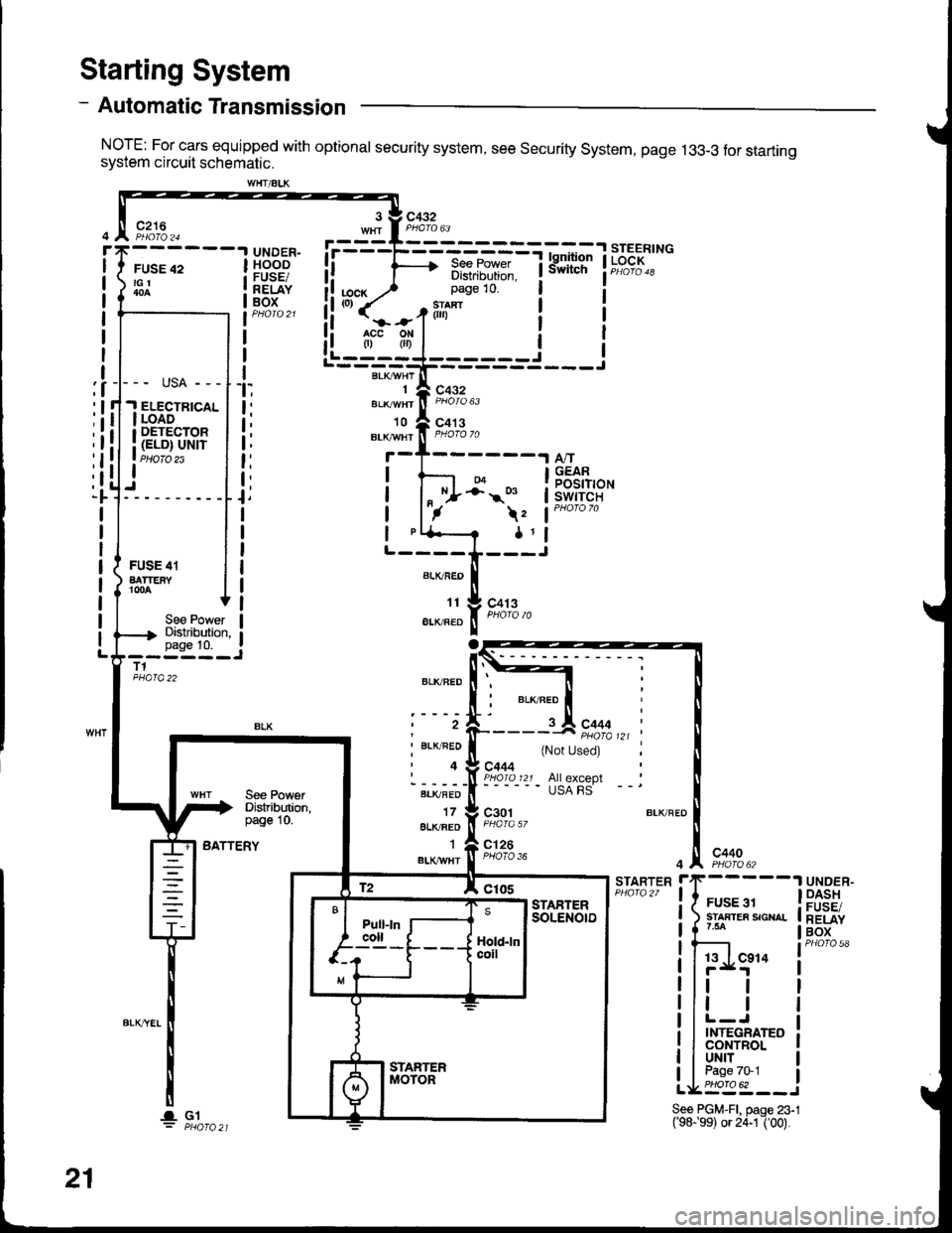
- Automatic Transmission
NorE: For cars equipped with optional security system, see security system, page 13g-3 tor startrngsystem circuit schematic.
Starting System
c216
FUSE 42tGt
UNDER-HOODFUSE/RELAYBOX
See PowerDistributian,page 10.
liu.) 3:i:it1-i*!
i!'''{=o1ili"' i i!i (=r.f(',ii i I
!i rfi,l.l i I
!L----J------j Ir'---BLK;HrT---------=---r
".o"rnrfi F,i% u.,
'to A co' s
3 V C432
BLr!,Y/Ht ll PHoro 70
04-;' s
\z
1l
t:
t,
t;
t:
t:
t,N^/.
A,/TGEARPOSITIONswtTcH
ALKFEO
't1
EIIVRED
BLKFED
t2
I BLK/RED
'4
BLI(FED
178LK/BEO'I
BLKII/HT
FUSE 41BATTEiYr00A
To
c413
See PowetDistribution,page 10.--i--;-JT1
BATTERY
c444
{Not Used)
All exceplUSA FS
c301
c126PHOTO 36c4404 ^, PHO|O 62
STARTERrrF-----1
! i rur..r !| snnrea sour- || 1 '* |
! Ir-'Lg"' i
llttl
llr | |
llL-J Ir I INTEGRATEo I! I CONTROL I
I luNrr I
tIbEt:_J
UNDER-DASHFUSE/RELAYBOX
WHT/ALK
--- usA ---
.I ELECTBTCALI LOADI DETECTOR
i (ELD) uNrr. PHOIO 23I
21
lGlSee PGM-FI, paqe 23.1('98.'99) or 24-1I OO).
Page 1431 of 1680
![ACURA INTEGRA 1998 Service Repair Manual - Manual Transmission
NOTE: For cars equipped with optional security system, see security system, page 133-3 for starting
system circuit schematic.
c432
FUSE 42tGl
c216
r
I
I
I
I
I
I
I
I
I
]
UNDER.HOO ACURA INTEGRA 1998 Service Repair Manual - Manual Transmission
NOTE: For cars equipped with optional security system, see security system, page 133-3 for starting
system circuit schematic.
c432
FUSE 42tGl
c216
r
I
I
I
I
I
I
I
I
I
]
UNDER.HOO](/img/32/56983/w960_56983-1430.png)
- Manual Transmission
NOTE: For cars equipped with optional security system, see security system, page 133-3 for starting
system circuit schematic.
c432
FUSE 42tGl
c216
r
I
I
I
I
I
I
I
I
I
]
UNDER.HOODFUSE/RELAYBOX
ELECTRICALloAoDETECTOR(ELD) UN|T
START(10
c432
.Joil0t)
BLKWHT
1
BLK/IVHT
(o) ,t-,>
0)
,i
I
l
Ia
I
I
I
I
BLKA''HT II--2 A cqqz
"4
".u,".0^ tr-
- -----
t I coee
Hifr*',;*-"J
":-r
"*'
: See Ground
I Rl"i:b,*?"
""1;
' PHOIO 56
STARTERCUTRELAY
See PowerDistribution,page 10.
T1PHO|Q22
BLK/REO
BLK/BEO
a=z
lt
lta c444
Used)
c444All exceptUSA RS
See PolYerDistribution,page 10.
BLK/REO
1
ALK/WHI
c301
c126PHOTA 36c440
BATTERYSTARTERrrF-----1
! { H:.i,r'",""^. I
li ?.ea I
!l';Lg" i
|r | |
ill l lllL-J I! I INTEGRATED ]| | coNrRoL I
Ll'l,l't--i
UNDER.DASHFUSE/RELAYBOX
See PGM'Fl, page 23-l('98-99) or 24-1 ('00).
t2 A Clos
-a- G1
21-1
Page 1434 of 1680
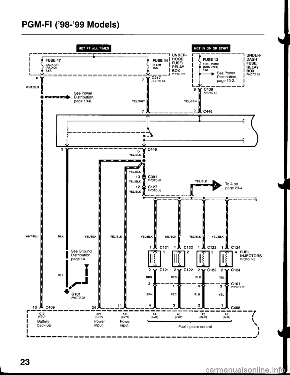
PGM-Fl ('98-'99 Models)
UNDER.OASHFUSE/RELAYBOX
- -6J C446
YEUELK I
YEUBLK
13YEL/BLK
12YEL/BLK
c301
c127
YELlBLK
See GroundDistribution,page 14.
V
I
,-J
G101
10za ^--- 11
c10 M4 A11 ,aL4 A3 A2 41 '(vBU) (lcp2) (GFr) (rNJ1) 0NJ2) (rNJ3) (rNJ4) !Battery Power Power e \oic[-rjp ;"ira input Fuel injector controt \
L
o
23
Page 1442 of 1680
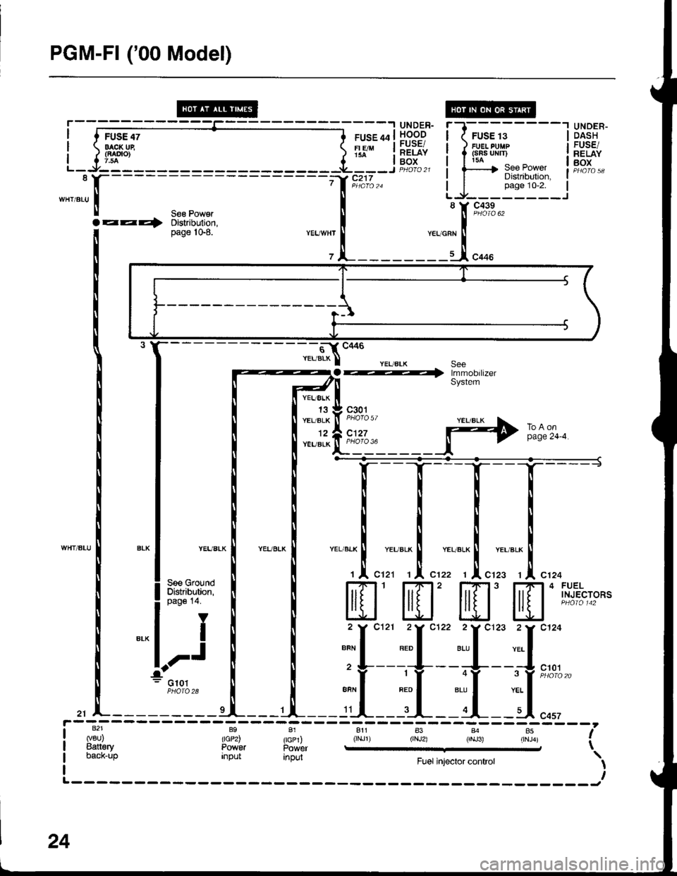
PGM-FI ('00 Model)
FUSE 47BACK Ui(FAOTO)7.54
--_.I UNDER-
ruse qa | !.o.^o-g
Tlouu | ;".iii
FUSE 13FUEI PUMP(sRs uNn)
UNDER-DASHFUSE/RELAYBOXI doi__-J PHOfQ 21
7 | in-oro za
il
See PowerDistribution,page'10-2.
S€e Powelza4 Distribution,page |0-8.YEUWHT
- - s- cccs
YEUBLK ISeea -; rmm^h,rzerSystem
YEUELK
13YEL/ALK
12YEUBLK
c301
c'127ToAonpage 24-4.
WHT/BLU
c1013 Y iniclr6 zo
PHOfO 28
9'l
I back-up input anpul Fuel injector controt \lr,,L------- ______r
----J
24
Page 1445 of 1680
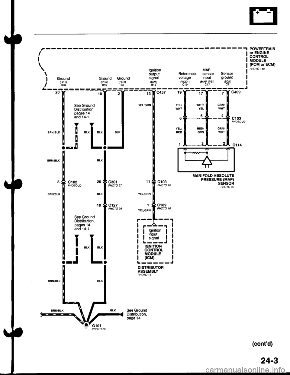
lgnition MAP
d',rtput Rsfetenag sensor Sensor
I Ground Ground Groud signal vollago input ground
: rLGl) (r,Gzl rpclr rtcM) (vccl) {MAP eB) (sG1)I B2o Blo 82 413 c19 c17 c7
I
I
\
MANIFOLD ABSOLUTEPRESSURE (MAP)SENSOR
POWERTRAINor ENGINECONTROLMODULE(PCM o. ECM)
c102c301
c127i[::
YEUGRN
See GroundDistribution,paos 14.
10
See GroundDistribution,pages !4and 1+1.
-i
"L
:p
I lg:Ll- I
I ii5ilr I
lGNtTtot{coxTnolMODULf
0cM)L-----J
DISTRIBUTORASSEMBLY
(cont'd)
24-3