check engine ACURA INTEGRA 1998 Service Repair Manual
[x] Cancel search | Manufacturer: ACURA, Model Year: 1998, Model line: INTEGRA, Model: ACURA INTEGRA 1998Pages: 1680, PDF Size: 53.14 MB
Page 57 of 1680
Engine Removal/lnstallation
{cont'dl
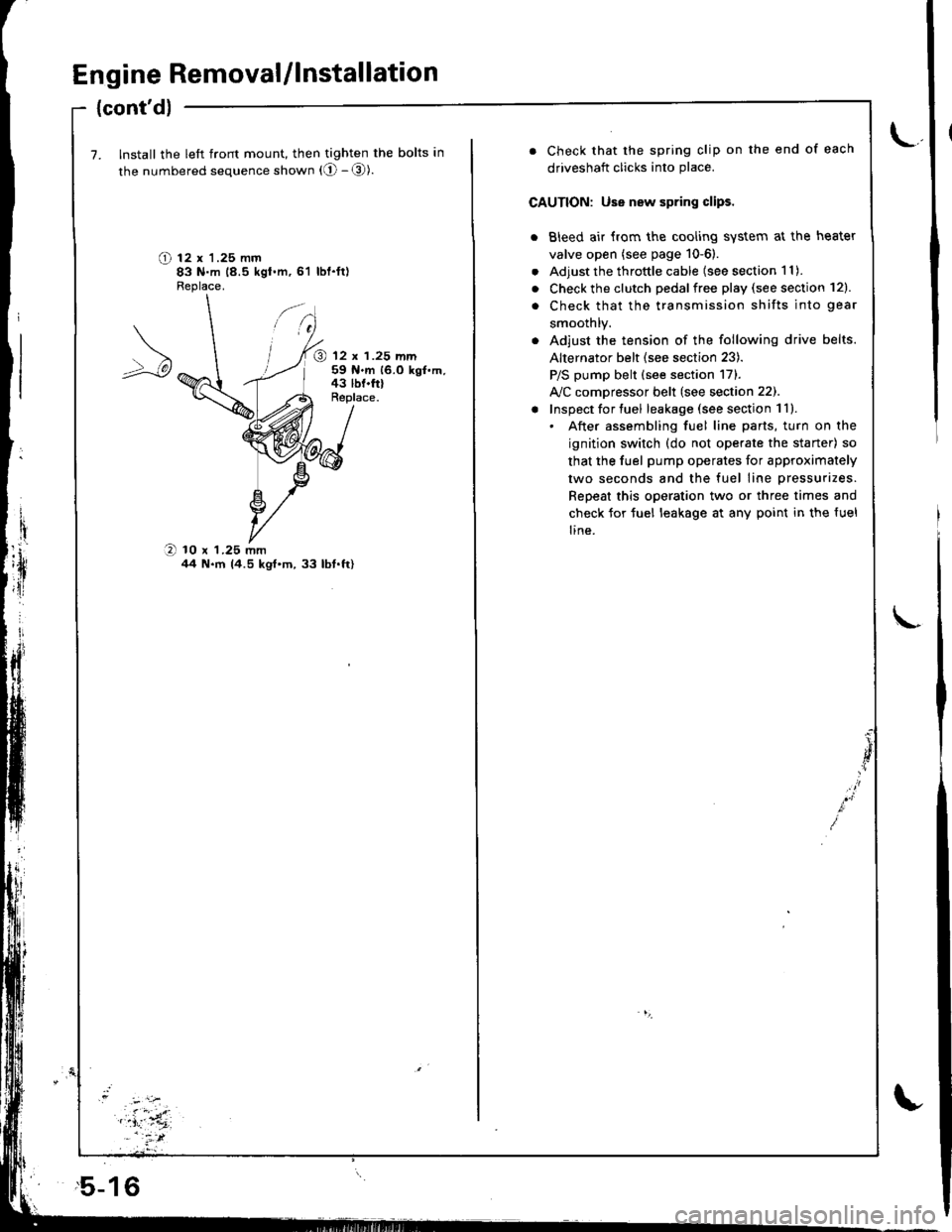
7. Install the left front mount, then tighten the bolts in
the numbered sequence shown (O - @).
O t2 x '1.25 mm83 N.m 18.5 kgt.m,61 lbl.ft)Fleplace.
@ 12 x 1.25 mm59 N.m 16.0 kgf.m,43 lbf.frlReplace.
O 10 x 1.25 mmil4 N.m 14.5 kgt'm,33 lbt.ft)
,5-16
. Check that the spring clip on the end of each
driveshaft clicks into place.
CAUTION: Use new spring clips.
. Bleed air {rom the cooling system at the heater
valve open (see page 10-6).
. Adjust the throttle cable (see section 1 1).
. Check the clutch pedalfree play (see section 12).
. Check that the transmission shifts into gear
smoothlY.
. Adjust the tension of the following drive belts.
Alternator belt {see section 23).
P/S pump belt (see section 171.
A/C comDressor belt (see section 22).
! Inspect for tuel leakage (see section 1ll.. After assembling fuel line parts, turn on the
ignition switch (do not operate the staner) so
that the fuel pump operates for approximately
two seconds and the fuel line pressurizes.
Repeat this operation two or three times and
check for tuel leakage at any point in the {uel
line.
Page 91 of 1680
Cylinder Head
Wapage
NOTE: lf camshaft-to-holder oil clearances (see page 6
22) arc nol within specification, the head cannot be
resurfaced.
lf camshaft-to-holder oil clearances are within specifica-
tions, check the head for warpage.
lf warpage is less than 0.05 mm (0.002 in) cylinder
head resurfacing is not required.
lf warpage is between 0.05 mm (0.002 in) and 0.2 mm
(0.008 in). resurface cylinder head.
Maximum resurface limit is 0.2 mm (0.008 in) based
on a height of 132.0 mm (5.20 in).
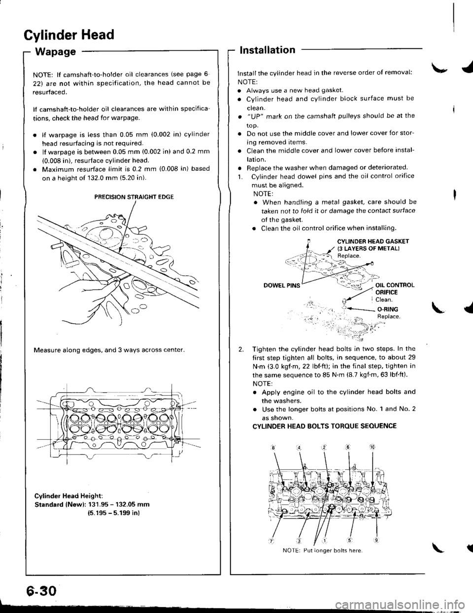
Measure along edges, and 3 ways across center.
Cylinder Head Height:
Standard lNewl: 131.95 - 132.05 mm(5.195 - 5.199 inl
lnstallation
Install the cylinder head in the reverse order of removal:
NOTE:
. Always use a new head gasket.
. Cylinder head and cYlinder block surface must be
clean.
. "UP" mark on the camshaft pulleys should be at the
to p.
. Do not use the middle cover and lower cover for stor-
ing removed items.
. Clean the middle cover and lower cover before instal-
lation.
. Replace the washer when damaged or deteriorated
L Cylinder head dowel pins and the oil control orifice
must be aligned.
. When hand'ing a metal gasket, care should be
taken not to fold it or damage the contact surface
of the gasket.
. Clean the oil control orifice when installing,
OIL CONTROLORIFICE
PRECISION STRAIGHT EDGE
6.30
CYLINDER HEAD GASKET
{3 LAYERS OF METAL)
DOWEL
Tighten the cylinder head bolts in two steps. In the
tirst step tighten all bolts, in sequence, to about 29
N.m (3.0 kgf.m,22 lbf.ft); in the final step. tighten in
lhe same sequence to 85 N.m (8.7 kgnm,63 lbf.ft).
NOTE:
. Apply engine oil to the cylinder head bolts and
the washers.
. Use the longer bolts at positions No. 1 and No. 2
as snown,
CYLINDER HEAD BOLTS TOROUE SEOUENCE
\.l
tNOTE: Put longer bolts here.
t-
Page 94 of 1680
15.
16.
17.
Install the timing belt (see page 6-12).
Adjust the valve clearance (see page 6-3).
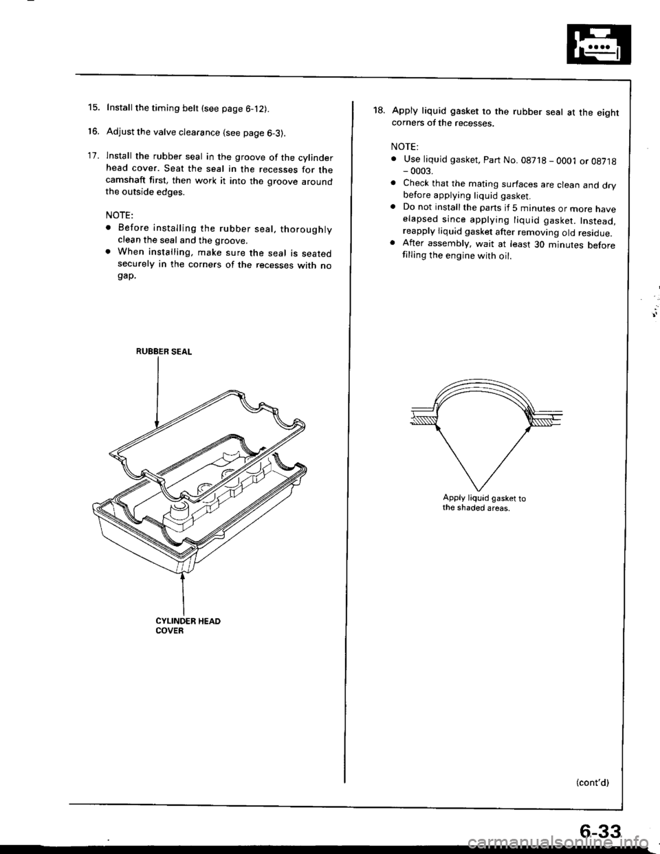
lnstall the rubber seal in the groove of the cylinderhead cover. Seat the seal in the recesses for thecamshaft first, then work it into the groove aroundthe outside edges.
NOTE:
. Before installing the rubber seal, thoroughlyclean the seal and the groove.
. When installing, make sure the seal is seatedsecurely in the corners of the recesses with nogap.
RUEBER SEAL
18.Apply liquid gasket to the rubber seal at the eightcorners of the recesses.
NOTE:
. Use liquid gasket, Part No. 08718 - OO01 or 08718- 0003.
. Check that the mating surfaces are clean and drybefore applying liquid gasket.. Do not installthe parts if 5 minutes or more naveelapsed since applying liquid gasket. Instead,reapply liquid gasket after removing old residue.. After assembly, wait at least 30 minutes beforefilling the engine with oil.
Apply liquid gasket tothe shaded areas.
(cont'd)
6-33
Page 146 of 1680
I
lllustrated Index
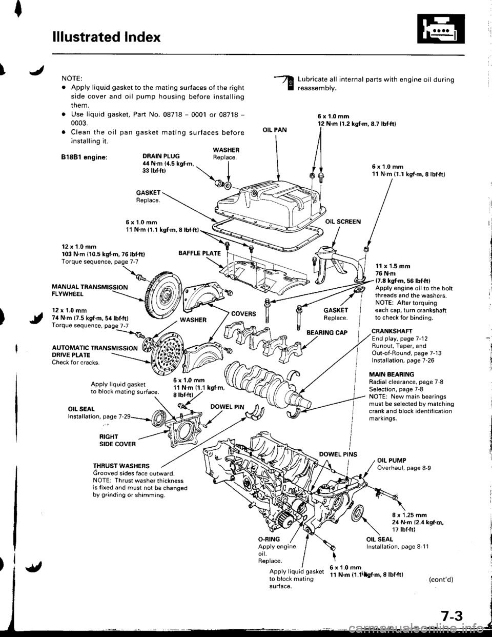
INOTE:
. Apply liqujd gasket to the mating surfaces ot the right
side cover and oil pump housing before installing
them.
. Use liquid gasket,
0003.
. Clea n the oil pan
installing it.
B18Bl engine:
Part No. 087'18 - 0001 or 08718 -
gasket mating surfaces before
Lubricate all internal parts with engine oil during
reassemDly.
6x1.0mm12 N.m {1.2 kg{.m,8.7 lbt.ft}
6x1.0mm11 N.m 11.1 kg'f.m,8 lbt.ftl
OIL SCREEN
DEAIN PLUG4il N.m 14.5 kgt m,33 tbtft)
BAFFLE PLATE
6x1.0mm1'l N.m (1.1 kgt.m,8 rbr.ftl
OIL PAN
O.FING
CAP
DOWEL PINS
WASHERReplace.
GASKETReplace.
6x1.0mm11 N.m (1.1 kgl.m, 8 lbl.ft)
12 x 1.0 mm103 Nm 110.5ks{.m,76lbf.ft}
MANUAL TRANSMISSIONFLYWHEEL
12 x 1.0 mm74 N.m 17.5 kgf.m,54lbf.tr)Torque sequence, page 7-7
AUTOMATIC TRANSMISSION
WASHERcovERsGASKETReplace.
11 x 1.5 mm76 N.m17.8 kgt m, 56 lbtft)Apply engine oilto the boltthreads and the washers.NOTE: After torquingeach cap, turn crankshaftto check for binding.
ORIVE PLATECheck for cracks.
Apply liquid gasketto block mating surface.
CRANKSHAFTEnd play, page 7-12Runout, Taper, andOut-of'Round, page 7-13Installation, page 7-26
MAIN AEARINGRadialclearance, page 7 8Selection, page 7'8NOTE: New main bearingsmust be selected by matchingcrank and block identificationmarkrngs.
I
i
OIL SEALlnstallation, page 7
RIGHTSIDE COVER
THRUST WASHERSGrooved sides face outward.NOTE: Thrust washer thicknessis fixed and must not be changedby grinding or shamming.
8 x 1.25 mm21 N..n l2.1kga'r,�,17 tbf.ft)
OIL SEALInstallation, page 8-1 1Apply engineorl.Replace.
Apply liquid gasket
to block matingsurface,
6x1.0mm11 N.m t1.lilh{.m,I lbf.ft}(cont'd)
Page 148 of 1680
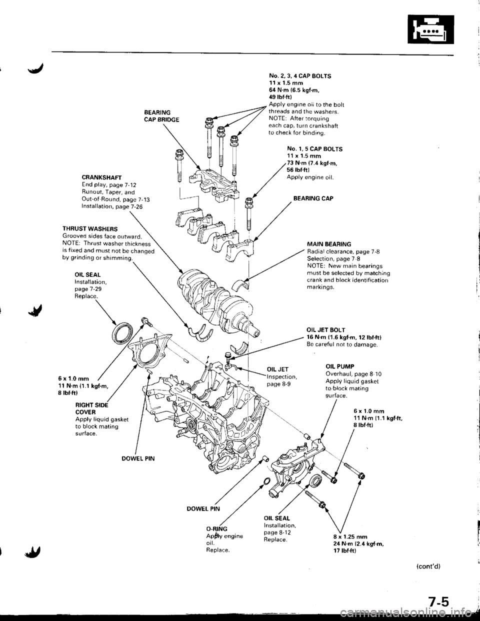
BEARINGCAP BRIOGE
No. 2.3,4 CAP BOLTS11x 1.5 mm64 N.m {6.5 kgt.m,49 tbtftlApply engine oi/ to the bohthreads and the washers.NOTE: After torquingeach cap, turn crankshaftto check for binding.
No. 1,5 CAP BOLTS11 x '1.5 mm73 N.m (7.4 ksl.m,56 tbf.ft)Apply engine oil.
BEARING CAP
CRANKSHAFTEnd play, page 7-12Bunout, Taper, andOut-of Round, page 7-13Installation, page 7-26
THRUST WASHERSGrooved sides face outward_NOTE: Thrust washer thicknessis {ixed and must not be changedby grinding or shimming.
OIL SEALInstallation,page 7 -29
Replace.
MAIN BEARINGRadial clearance, page 7-8Selection, page 7 INOTE: New main bearingsmust be selected by matchingcra nk and block identificationmarkrngs,
6x1-0mm11 N.m {l.1 kgf.m,I rbr.ft)
OIL JET BOLT16 N.m {1.6 kgf.m, 12lbtft}Be.careful not to damage.
OIL PUMPOverhaul, page 8 10Appl/ liquid gasketto:block mating
RIGHT SIDECOVERApply liquid gasketto block matingsurface.
6x1.0mm11 N.m 11.1 kgf.ft,8lbf.ft)
OOWEL PIN
DOWEL PIN
OIL SEALInstallation,page 8-12Replace.8 x 1.25 mm24 N.m {2.4 kg{.m,17 tbt.ftl
(cont'd)
-,tr
t-9 i.lt
Page 151 of 1680
/
li
l
Main Bearings
Clearance
2.
3.
1.
4.
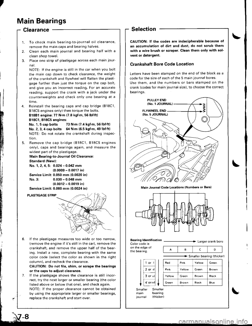
To check main bearing-to-iournal oil clearance,
remove the main caps and bearing halves.
Clean each main iournal and bearing half with a
clean shop towel.
Place one strip of plastigage across each main iour-
na l-
NOTE: lf the engine is still in the car when you bolt
the main cap down to check clearance, the weight
of the crankshaft and flywheel will flatten the plasti'
gage further than just the torque on the cap bolt,
and give you an incorrect reading. For an accurate
reading, support the crank with a jack under the
counterweights and check only one bearing at a
trme.
Reinstall the bearing caps and cap bridge (B18C1,
B18C5 engines only)then torque the bolts.
Bl8Bl engine: 77 N'm (7.8 kgt.m.56lbf.ft)
B18Cl,818C5 engines:
No. 1,5 cap bolts 73 N.m (7.4 kgf.m,56lbnftl
No. 2. 3, 4 cap bolts 64 N.m {6.5 kgf m. 49 lbf ftl
NOTE: Do not rotate the crankshaft during inspec-
tro n.
Remove the cap bridge (818C1, 818C5 engines
only), caps and bearings again, and measure the
widest part of the plastigage.
Main Bearing-to-Journal Oil Clearance:
Standard lNew):
No. 1, 2, 4, 5: 0.024 - 0.042 mm
10.0009 -0.0017 in)
Service Limit:0.050 mm (0.0020 in)
No.3:0.030 - 0.048 mm
10.0012 - 0.0019 inl
Service Limit:0.060 mm {0.0024 inl
PLASTIGAGE STRIP
lf the plastigage measures too wide or too narrow,
{remove the engine if it's still in the car), remove the
crankshaft, and remove the upper half of the bear-
ing. lnstall a new, complete bearing with the same
color code (select the color as shown in the right
column), and recheck the clearance.
CAUTION: Do not file, shim. or scrape the bearings
or the caps to adiust clearance.
lf the plastigage shows the clearance is still incor-
rect, try the next larger or smaller bearing (the color
listed above or below that one), and check again.
NOTE: lf the oroDer clearance cannot be obtained
by using the appropriate larger or smaller bearings.
reolace the crankshaft and start over.
Selection
CAUTION: lf the codes ale indecipherable because of
an accumulation oI dirt and dust, do not scrub them
with a wire bru6h or scraper. Clean lhem only with sol-
vent or detergent.
Crankshaft Bore Code Location
Letters have been stamped on the end of the block as a
code for the size of each of the 5 main iournal bores
Use them, and the numbers or bars stamped on the
crank {codes for main journal size), to choose the correct
Dean nqs,
FLYWHEEL END
Main JouhalCode Locations (Numbe.s or Bars)
Bearing ldentif ic.tionColor code ison the edge ofthe bearing.
Larger crank bore
acD
"""""""" Smallerbearingithicker)
Green
Elack
B'ownBlackElue
Smaller Smallermain bearingjournal lthacker)
Page 152 of 1680
I
IConnecting Rod Bearings
Clearance
1. Remove the connecting rod cap and bearing half.2. Clean the crankshaft rod journal and bearing halfwith a clean shop towel.
3. Place the plastigage across the rod journal.
4. Reinstall the bearing half and cap, and torque thenuts (818C5 engine: see page 7-19).
81881 engine:31 N.m (3.2 kgnm,23 tbf.ftl
Bl8Cl engine:44 N.m (4.5 kgl.m.33 tbl.ft)
NOTE: Do not rotate the crankshaft during inspection.
Connecting Rod Bearing-to-Journal Oil Clearance:81881 engine:
Standard {Newl: 0.020 - 0.038 mm
{0.0008 - 0.0015 inl
Service Limit: 0.050 mm {0.0020 inl
818C1 engine:
Standald {Newl: 0.032 - 0.050 mm
10.0013 - 0.0020 in)
Service Limit: 0.060 mm {0.0024 in}
B18C5 engine:
Standard lNew): 0.038 - 0.050 mm(0.0015 - 0.0020 inl
Service Limit: 0.060 mm t0.0024 inl
lf the plastigage measures too wjde or too narrow,remove the upper half of the bearjng, install a new,complete bearing with the same color code (select
the color as shown in the rig ht column), andrecheck the clearance.
CAUTION: Do not file, shim, or scrape the bearingor the caps to adiust clearance.
It the plastigage shows the clearance is still incorrect,try the next larger or smaller bearing (the color listedabove or below that one), and check clearance again.
NOTEr It the proper clearance cannot be obtainedby using the appropriate larger or smaller bearings,replace the crankshaft and stan over.
Selection
CAUTION: lf the codes are indecipherable because ofan accumulation of dirt and dust, do not scrub themwith a wire brush or scraper. Clean them only with sol-vent or delergent.
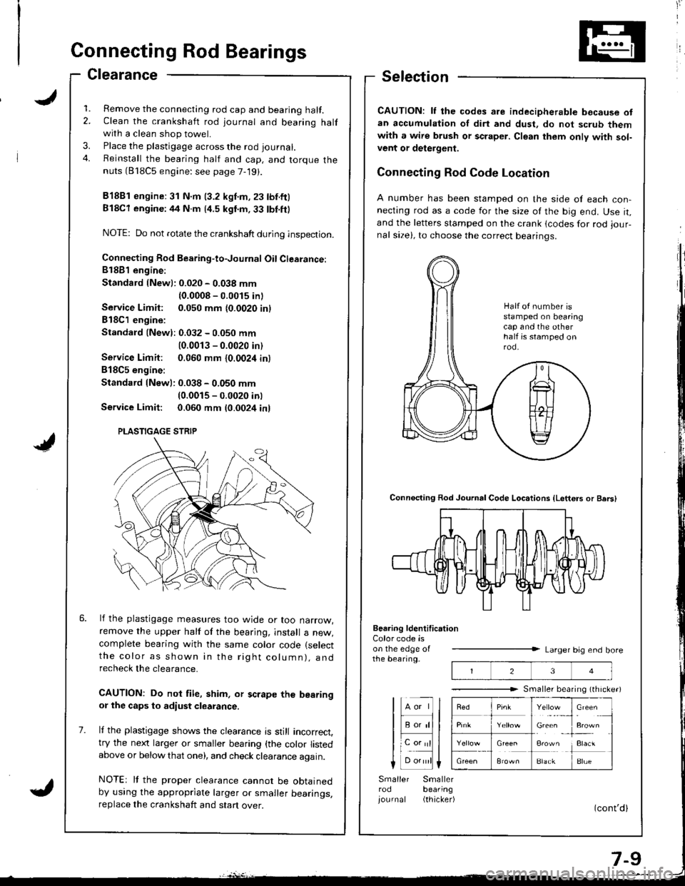
Connecting Rod Code Location
A number has been stamped on the side of each con-necting rod as a code for the size of the big end. Use it,and the letters stamped on the crank lcodes for rod iour-nal size), to choose the correct bearinqs.
Connecting Rod Journal Code Loc.tions {Letters or Bers)
Beering ldentification
23
Y"rl.:_,
Gie& ,
!**
i:1"
BlackBlue
Color code ison the edge oIthe bearing.Larger big end bore
Smaller bearing (th rche.)
lHll
I F;;lll
lL".;|l
Smaller Smallerrod bearing
iournal (thicker)
Half ot number isstamped on bearingcap and the otherhalf is stamped onrod.
PLASTIGAGE STRIP
Page 157 of 1680
Cylinder Block
Inspection
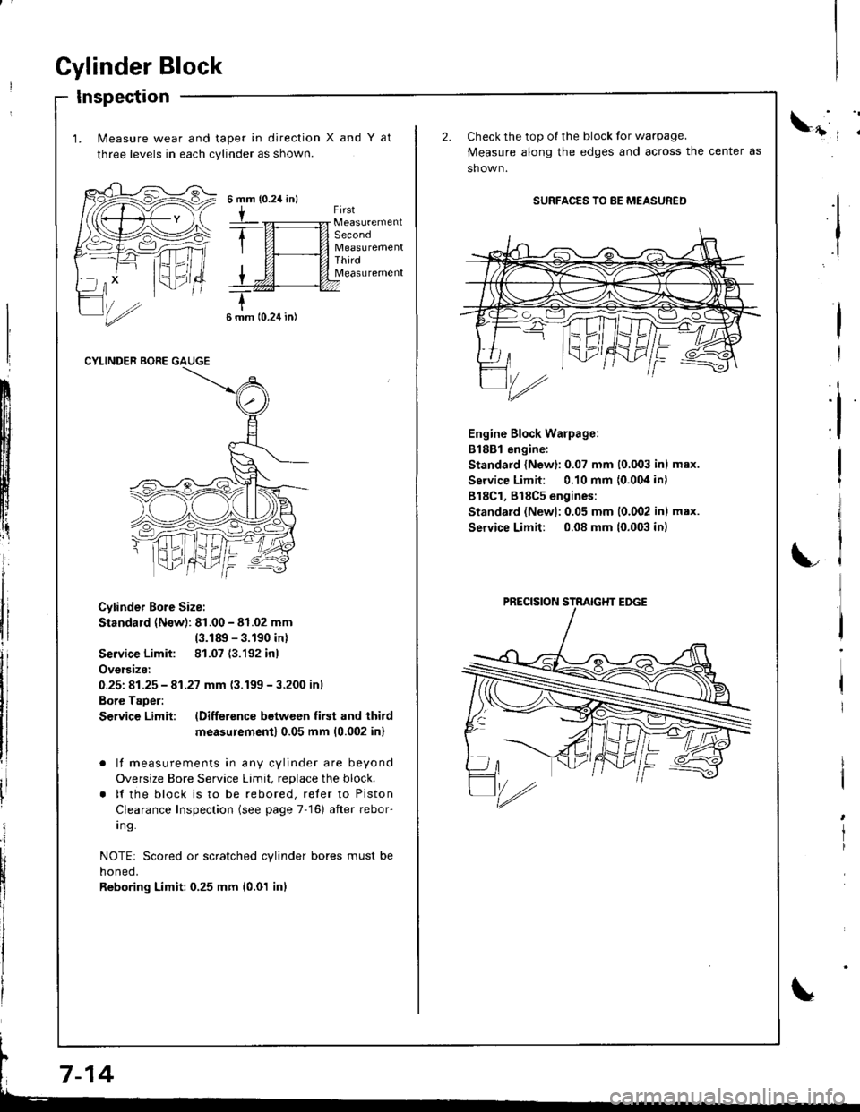
1. Measure wear and taper in direction
three levels in each cylinder as shown.
XandYat
{0.24 in}6mm
tFirst
Second
ThirdMeasurement
6 mm 10.24 in)
CYLINDER BORE GAUGE
Cylinder Bore Size:
Standard (N€w): 81.00 - 81.02 mm
(3.189 - 3.190 inl
Service Limit: 81.07 (3.192 inl
Oversize:
0.251 81.25 - 41.27 mm 13.199-3.200 inl
Bore Taoer:
S€rvice Limit: lDifference betwcen first and third
measu;ement) 0.05 mm (0.002 inl
. lf measurements in any cylinder are beyond
Oversize Bore Service Limit, replace the block.
. lf the block is to be rebored, reler to Piston
Clearance Inspection (see page 7-16) after rebor-
I ng.
NOTE: Scored or scratched cylinder bores must be
noneo,
Reboring Limit: 0.25 mm (0.01 inl
ll
:i
I
I
Check the top oI the block for warpage.
Measure along the edges and across the center as
sh own.
SURFACES TO 8E MEASURED
Engine Block Warpage:
B188l engine:
Standard {New}: 0.07 mm (0,003 inl max.
Service Limit: 0.10 mm {0.004 in)
818C1, 818C5 engines:
Standard (Newl:0.05 mm 10.002 inl max.
Service Limit: 0.08 mm (0.003 in)
I
I
rl
LC
'/rz
PRECISION STRAIGHT EDGE
Page 160 of 1680
t
Installation
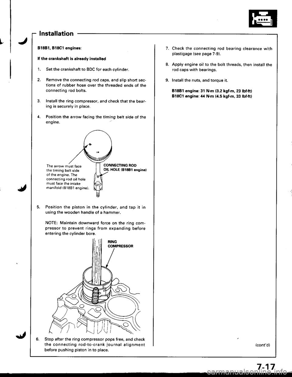
Bl881, 818C1 enginos:
lf the crankshaft is already installed
'1. Set the crankshaft to BDC for each cylinder.
2, Remove the connecting rod caps, and slip short sec-
tions of rubber hose over the threaded ends of the
connecting rod bolts.
3. Install the ring compressor, and check that the bear-
ing is securely in place.
4. Position the arrow facing the timing belt side of the
eng ine.
The arrow must facethe timing belt sideot the engine. Theconnecting rod oil holemust face the intakemanjfold (81881 engine).
CONNECTING ROOOIL HOLE {81881 enginel
Position the piston in the cylinder. and tap it in
using the wooden handle of a hammer.
NOTE; Maintain downward force on the ring com-pressor to prevent rings from expanding before
entering the cylinder bore.
6. Stop after the ring compfessor pops free, and check
the connecting rod-to-crank journal alignment
betore pushing piston in to place,
7.Check the connecting rod bearing clearance withplastigage {see page 7-9).
Apply engine oil to the bolt threads. then install the
rod caps with bearings,
Installthe nuts, and toroue it.
81881 engine: 31 N.m {3.2 kgf.m, 23 lbf.ft)
BlSCt engine: il4 N.m {i[.5 kgf.m, 33 lbf.ft)
(cont'd)
7-17
Page 161 of 1680
I
i
Pistons
Installation (cont'dl
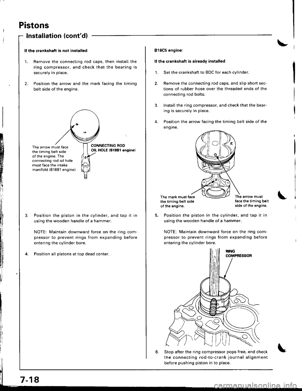
ll the crankshaft is not installed
1. Remove the connecting rod caps, then install the
ring compressor. and check that the bearing is
securely in place.
2. Position the arrow and the mark facing the timing
belt side of the engine.
ItIl
Iti
tfll|lflI[lrB
[:
i"lrt
i'
ff
ll,
illi
llillr
il
The arrow must facethe timing belt sideof the engine. Theconnecting rod oil holemust face the intakemanilold (8188'l engine).
Position the piston in the cylinder, and tap it in
using the wooden handle of a hammer.
NOTE: Maintain downward force on the ring com-
pressor to prevent rings from expanding before
entering the cylinder bore.
Position all pistons at top dead center.
7-18
818C5 engine:
ll the crankshaft is already installed
1. Set the crankshaft to BDC for each cylinder.
2. Remove the connecting rod caps, and slip short sec-
tions of rubber hose over the threaded ends of the
connecting rod bolts.
3. Install the ring compressor, and check that the bear-
ing is securely in place.
4. Position the arrow facing the timing belt side of the
eng ine.
The mark must facethe timing belt sideof the engine.
The arrow mustlace the timing beltside of the engine.
Position the piston in the cylinder, and tap it in
using the wooden handle of a hammer.
NOTE: Maintain downward iorce on the ring com-
pressor to prevent rings from expanding before
entering the cylinder bo.e.
6. Stop after the ring compressor pops free, and check
the connecting rod-to-crank journal alignment
before pushing piston in to place.