exhaust ACURA INTEGRA 1998 Service Repair Manual
[x] Cancel search | Manufacturer: ACURA, Model Year: 1998, Model line: INTEGRA, Model: ACURA INTEGRA 1998Pages: 1680, PDF Size: 53.14 MB
Page 41 of 1680
ra
Engine
Engine Removal/lnstallation ............. 5-1
Cylinder Head/Valve Train ............... 6-1
Engine Block ......... ........7-1
Engine Lubrication .........8-1
Intake Manifold/Exhaust System ...... 9-1
Cooling ....... 10-1
Page 50 of 1680
7
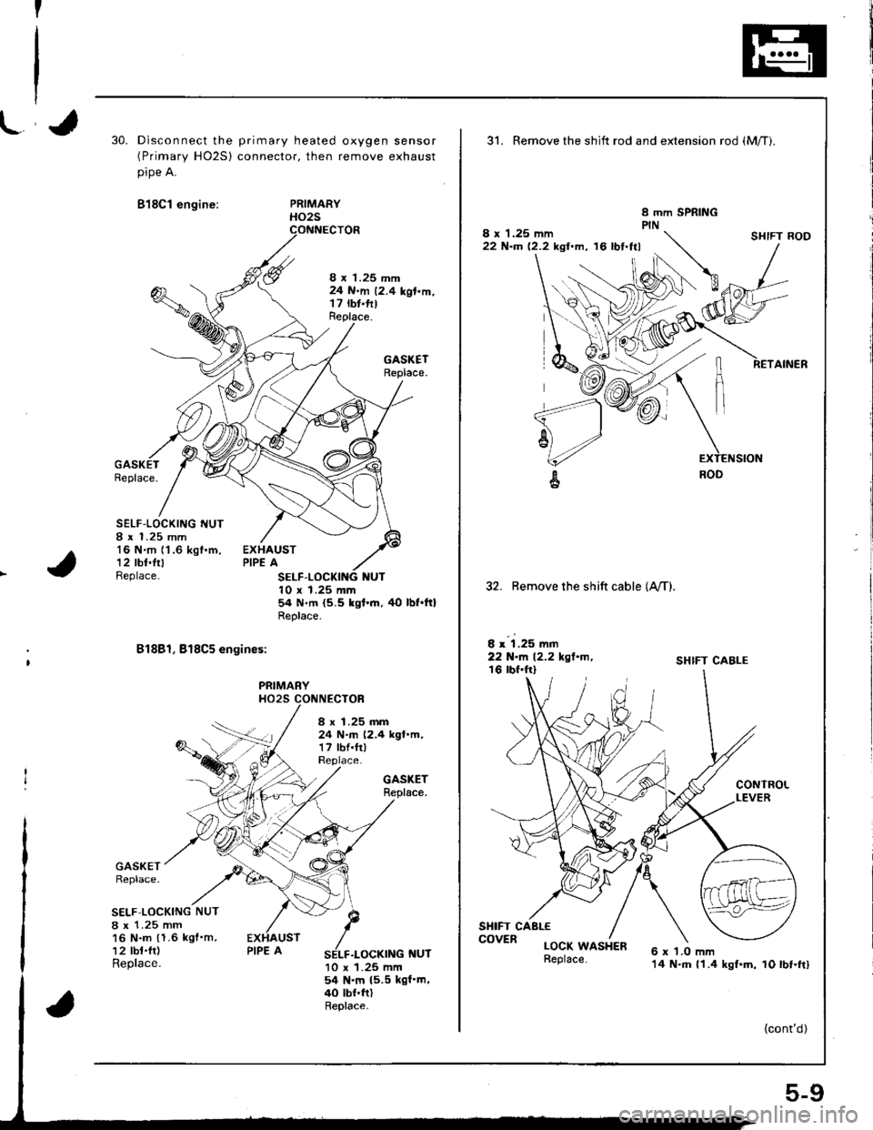
30.Disconnect the primary heated oxygen sensor(Primary HO2S) connector, then remove exhaust
pipe A.
818C1 engine:PRIMARYHO2S
8 x 1.25 mm24 N.m 12.4 kgl.m.t7 rbt.fttReplace.
GASKETReplace.
Replace.
SELF-LOCKING I{UT8 r 1.25 mm16 N.m (1 .6 kgf .m,
12 tbt.frtBeplace.
EXHAUSTPIPE A
NUT10 x 1.25 mm54 N.m {5.5 kgt'.n, tlo lbt.ft}Replace.
81881, 818C5 engines:
PRIMARYHO25 CONNECTOF
GASKETReplace.
GASKETReplace.
S€LF.LOCKING NUT
8 x 1.25 mm16 N.m (1.6 kgf'm,12 tbt.fr)Replace.f{UT10 x 1.25 mm54 N.m {5.5 kgf'm,40 lbf.ftlReplace.
8 x 1.25 mm24 N.m (2.4 kgt.m,17 lbf.frlReplace.
31. Remove the shift rod and extension rod {Mff).
8 x 1.25 mm22 N'm 12.2 kgl.m, '16 lbt.ttl
32. Remove the shift cable (A,/T).
I x 1.25 mm22 N-l'. 12.2 kgl.m,16 lbf.frl
SHIFT CABLE
CONTROLLEVER
6 x 'l.O mm14 N.m {1.4 kgf.m, 10 lbt.ft}
SHIFT ROD
RETAINER
SHIFT CABLE
LOCK WASHER
{cont'd)
COVER
5-9
Page 64 of 1680
r.lJ
Valve Clearance
Adjustment
NOTE:
. Valves should be adjusted cold; at a cylinder head
temperature of less than 100'F (38"C).
Adjustment is the same for both intake and exhaust
valves.
. After adjusting, retorque the crankshaft pulley bolt to
177 N.m (18.0 kgf.m, 130 lbf'ft).
1. Remove cylinder head cover.
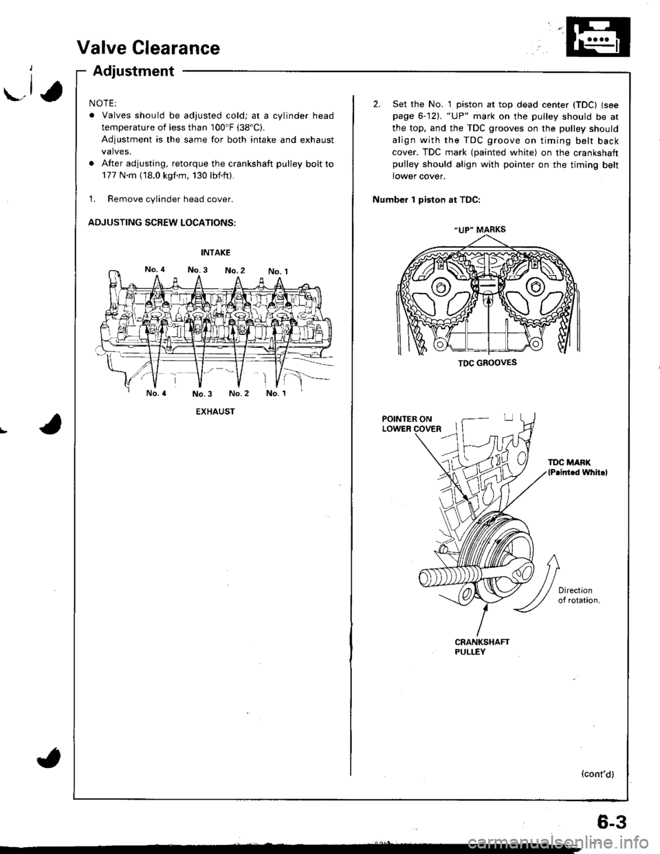
ADJUSTING SCREW LOCATIONS:
EXHAUST
(
"UP" MARKS
TDC GBOOVES
2. Set the No. 1 piston at top dead center (TDC) (see
page 6-12). "UP" mark on the pulley should be at
the top, and the TDC grooves on the pulley should
align with the TDC groove on timing belt back
cover. TDC mark (painted white) on the crankshaftpulley should align with pointer on the timing belt
lower cover.
Number 1 piston at TDC:
POINTER ONLOWER
TDC MAFK(P.inted whh.l
(cont'd)
6-3
Page 65 of 1680
Valve Clearance
Adjustment (cont'dl
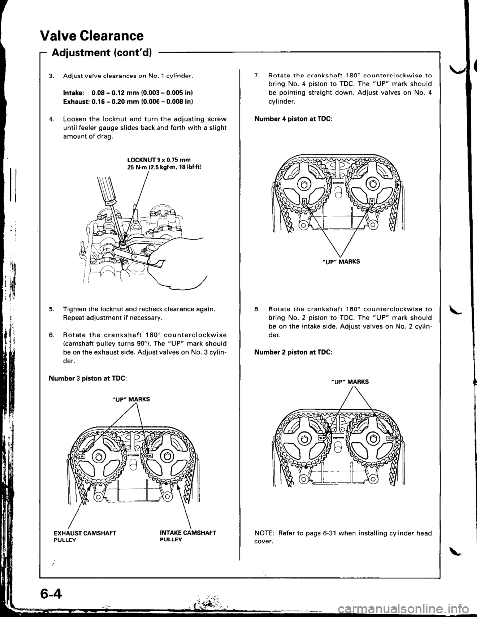
Adjust valve clearances on No. 1 cylinder.
Intske: 0.08 - 0.12 mm (0.003 - 0.005 inl
Exhaust: 0.15 - 0.20 mm (0.006 - 0.008 inl
Loosen the locknut and turn the adjusting screw
until feeler gauge slides back and forth with a slight
amount of drag.
7. Rotate the crankshaft 180' counterclockwise to
bring No. 4 piston to TDC. The "UP" mark should
be pointing straight down. Adjust valves on No. 4
cylinder.
Number 4 piston at TDC:
LOCKNUT9x0.75mm25 N.m {2.5 kgl.m, 18lbtft}
Tighten the locknut and recheck clearance again,
Repeat adjustment if necessary.
Rotate the crankshaft 180' counterclockwise(camshaft pulley turns 90'). The "UP" mark should
be on the exhaust side. Adjust valves on No,3 cylin-
der.
8. Rotate the crankshaft 180' counterclockwise to
bring No. 2 piston to TDC. The "UP" mark should
be on the intake side. Adjust valves on No. 2 cylin-
der.
Number 2 piston at TDC:
Number 3 Diston at TDC:
NOTE: Refer to page 6-31 when installing cylinder head
cover.
"UP" MARKS
"UP" MARKS
"UP" MARKS
Page 77 of 1680
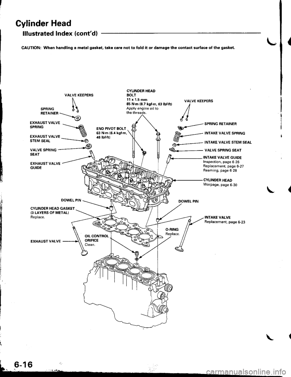
Gylinder Head
lllustrated Index (cont'd)
CAUTION: When handling a mstal ga€kot, take care not to fold it o. damage the contact surfac6 ol the gasket.{
VALVE KEEPERS
\
SPRTNG [\RETaTNER\_>6
CYLINDER IIEAOAOLT11 x'1.5 mm
EXHAUST VALVE
EXHAUST VALSPRINGs------.--
r
€.-=---
€<_-
VALVE KEEP€NS
DOWEL PIN
SPRING AEIAINER
INTAKE VALVE SPRING
INTAKE VALVE STEM SEAL
VALVE SPRING SEAT
ENO PIVOT BOLT63 N.m {6.4 kgf.m,46 tbt.ftlSIEM SEAL
VALVE SPRINGSEAT
-----------rg
,@
EXHAUST VALVEGUIDE
INTAKE VALVE GUIDEInspection. page 6 26Replacement, page 6,27Reaming, page 6 28
CYLINDER HEADWarpage, page 6,30
L
DOWEL PIN
CYLINDER HEAD GASKET(3 LAYERS OF METALIReplace.
EXHAUST VALVE
85 N.m (8.7 kgtm, 63 lbf.ft) IApply engine oilto /lthe threads. / |
/ {e
\
Page 81 of 1680
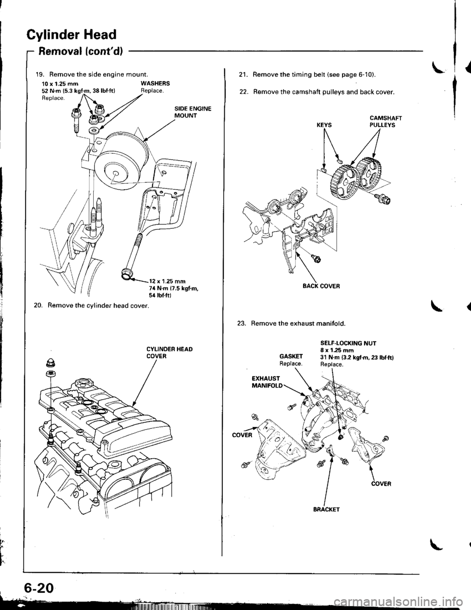
Gylinder Head
Removallcont'd)
19. Remove the side engine mount.
10 x 1.25 mm52 N.m {5.3 kgt:m, 38 lbl.ft}
20. Remove the cylinder head cover.
SIDE ENGINEMOUNT
12 x 1.25 mm74 N.m 17.5 kgt.m,sil lbtft)
CYLINOER HEADCOVER
t
L
I'
L21.
22.
Remove the timing belt (see page 6- 10).
Remove the camshaft pulleys and back cover.
CAMSHAFTPULLEYS
23. Remove the exhaust manifold.
GASKETReplace.
SELF.LOCKING NUT8 x 1.25 mm3'l N.m 13.2 kgl.m, 23 lbf.ftlReplace.
Page 84 of 1680
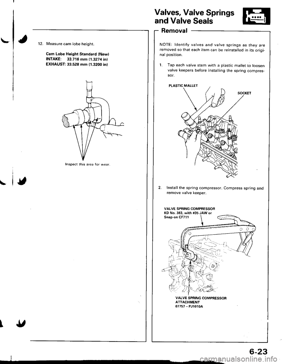
\-
Valves, Valve Springs
and Valve Seals
Removal
NOTE: ldentify valves and valve springs as they areremoved so that each item can be reinstalled in its origi-nal position.
1. Tap e€ch valve stem with a plastic mallet to loosen
valve keepers before installing the spring compres-sor.
Install the spring compressor. Compress spring andremove valve keeper.
VALVE SPRING COMPRESSORKD No.383, with #35 JAW orSnap-on CF711
Measure cam Iobe height.
Cam Lobe Height Standard (Newl
fNTAKE: 33.716 mm 11.3271inl
EXHAUST: 33.528 mm (1.3200 inl
\
\
VALVE SPRING COMPRESSORATTACHMENT07757 - PJ1010A
Inspect this area for wear.
;;:'
, -:.. "
'orl
._vn-'r'.'i),
I
6-23
Page 85 of 1680
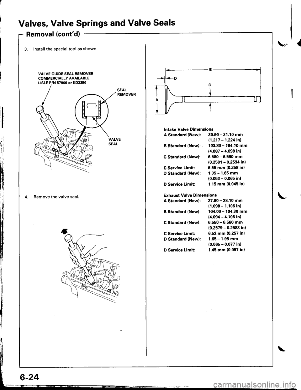
Valves, Valve Springs and Valve Seals
Removal (cont'dl
3. Installthe special tool as shown
VALVE GUIDE SEAL REMOVERCOMMERCIALLY AVAILABLELISLE P/N 57900 or KD3350
.i
'iii
tI
i{
lf
4. Remove the valve seal.
v,l
lntaks valve Dimsnsions
A Standard (Newl: 30.90 - 31.10 mm
B Standard (New):
C Standard {New):
C Sorvice Limit:
D Standard (Now):
D Service Limil:
B Standard (New):
C Standard {N6w}:
C Service Limit:
D Standsrd lNow):
D Servic€ Limit:
11-217 - 1.221inl
103.80 - 104.10 mm
14.087 - 4.098 in)
6.580 - 6.590 mm(0.2591 - 0.2594 in)
6.55 mm (0.258 inl
1.35 - 1.65 mm(0.053 - 0.065 in)'1.15 mm (0.0'15 inl
Exhaust Vslve Dimonsions
A Standard lNew): 27.90 - 28.10 mm\
11.098 - 1.106 in)
1O4.OO - 10,1.30 mm
l,[.09/t - 4.106 in)
5.550 - 6.560 mm
10.2579 - 0.2583 in)
6.52 mm (0.257 inl
1.65 - 1.95 mm
(0.065 - 0.077 in)
1.45 mm (0.057 in)
Page 86 of 1680
\-
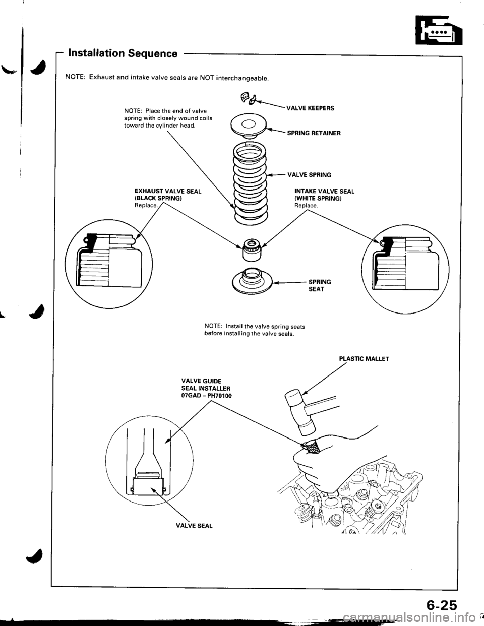
Installation Sequence
Exhaust and intake valve seals are NOT interchanoeable.
NOTE: Place the end of valvespring with closely wound coilstoward the cylinder head.
EXHAUST VALVE SEALIBLACK SPRING}Replace.
@A..'..--uoruEKEEPER'
9-...-'PRTNGREYATNER
VALVE SPRING
INTAKE VALVE SEALIWHITE SPRINGIReplace.
I
PLASTIC MALLET
VALVE GUIDESEAL INSTALLER07GAD - PH70100
,@.t.'( (Sz) I<-- SPRING
V SEAT
NOTE: lnstall the valve spring seatsbefore installing the valve seals.
6-25
Page 87 of 1680
Valve Installation'alve Inslallauon -
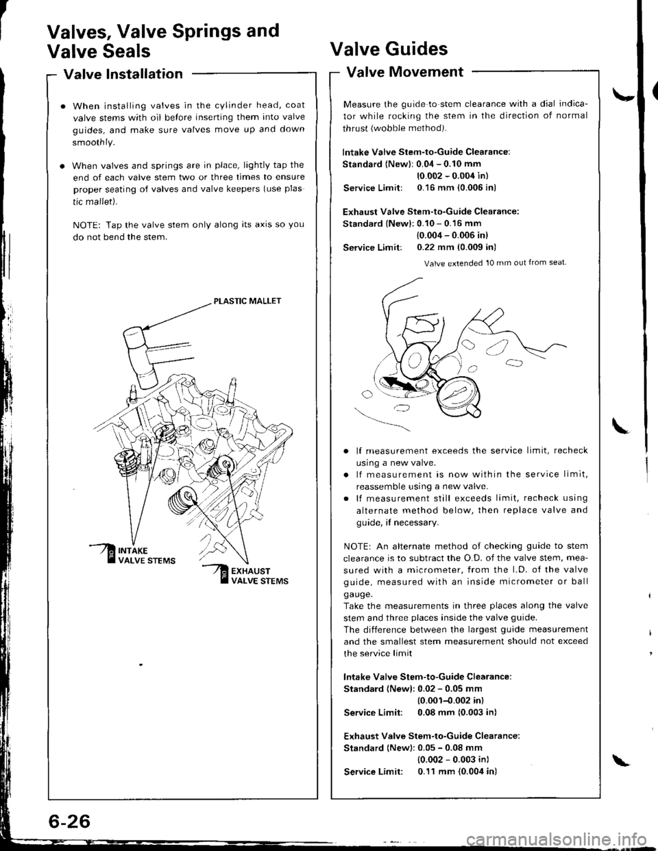
When installing valves in the cylinder head, coat
valve stems with oil belore inserting them into valve
guides, and make sure valves move up and down
smoothly.
When valves and springs are in place, lightly tap the
end of each valve stem two or three times to ensure
proper seating of valves and valve keepers (use plas
tic mallet).
NOTE: Tap the valve stem only along lts axrs so you
do not bend the stem.
PLASTIC MALLET
Valves, Valve Springs and
Valve SealsValve
Valve
Guides
Movement
\-
L
valve tvtovemenr -
Measure the guide to stem clearance with a dial indica-
tor while rocking the stem in the direction of normal
thrust {wobble method).
lntake Valve Stem-to-Guide Clearance:
Standard {Newlr 0.04 - 0.10 mm
10.002 - 0.004 in)
Service Limit: 0.16 mm {0.005 in)
Exhaust Valve Stem-to-Guide Clearance:
Standard {New}: 0.10 - 0.16 mm
(0.004 - 0.006 inl
Service Limit: 0.22 mm (0.009 in)
Valve extended 10 mm out from seat
lf measurement exceeds the service limit, recheck
usrng a new valve.
lf measurement is now within the service limit,
reassemble using a new valve.
lf measurement still exceeds limit, recheck using
alternate method below, then replace valve and
guide, if necessary.
NOTEr An alternate method of checking guide to stem
clearance is to subtract the O.D. of the valve stem, mea-
sured with a micrometer, from the l.D. o{ the valve
guide, measured with an inside micrometer or ball
ga uge.
Take the measurements in three places along the valve
stem and three places inside the valve guide.
The diiference between the largest guide measurement
and the smallest stem measurement should not exceed
the service limit
lntake Valve Stem-to-Guide Clearance:
Standard (Newl: 0.02 - 0.05 mm
10.001-{.002 inl
Service Limit: 0,08 mm (0.003 in)
Exhaust Valve Stem-to-Guide Clearance:
Standard (New): 0.05 - 0.08 mm
{0.002 - 0.003 in)
Service Limit: 0.11 mm {0.004 in)\