pulley ACURA INTEGRA 1998 Service Repair Manual
[x] Cancel search | Manufacturer: ACURA, Model Year: 1998, Model line: INTEGRA, Model: ACURA INTEGRA 1998Pages: 1680, PDF Size: 53.14 MB
Page 47 of 1680
Engine Ramoval/lnstallation
(cont'dl
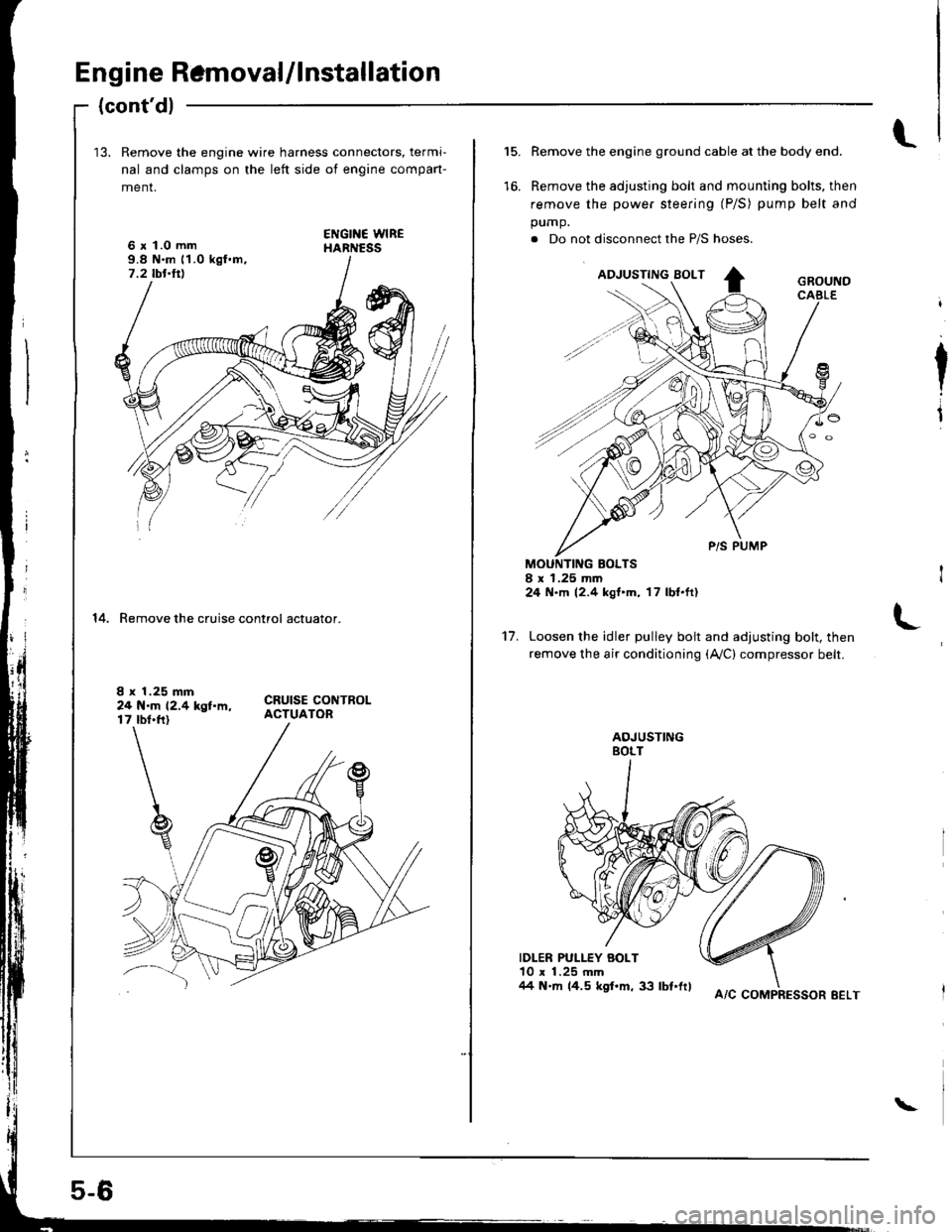
13. Remove the engine wire harness connectors, termi-
nal and clamps on the left side ot engine compan-
menr,
6 x 1.0 mm9.8 N.m 11.0 kgl.m,7.2 tbt.ttl
14. Remove the cruise control actuator.
I x 1.25 mm24 N.m 12.4 kgt.m,17 tbt.ft)
5-6
A/C COMPRESSOR EELT
\
l.15.
to.
Remove the engine ground cable at the body end.
Remove the adjusting bolt and mounting bolts, then
remove the power steering (P/S) pump belt and
pump.
. Do not disconnect the P/S hoses.
MOUNTING BOLTSI x 1.25 mm24 N.m 12.4 kgt'm, 17 lbl.ft)
Loosen the idler pulley bolt and adjusting bolt, then
remove the air conditioning (Ay'C) compressor belt.
IDLER PULLEY BOLT10 x 1.25 mm/14 N'm 14.5 kgf.m, 33 lbt'frl
I
I
't7.
Page 64 of 1680
r.lJ
Valve Clearance
Adjustment
NOTE:
. Valves should be adjusted cold; at a cylinder head
temperature of less than 100'F (38"C).
Adjustment is the same for both intake and exhaust
valves.
. After adjusting, retorque the crankshaft pulley bolt to
177 N.m (18.0 kgf.m, 130 lbf'ft).
1. Remove cylinder head cover.
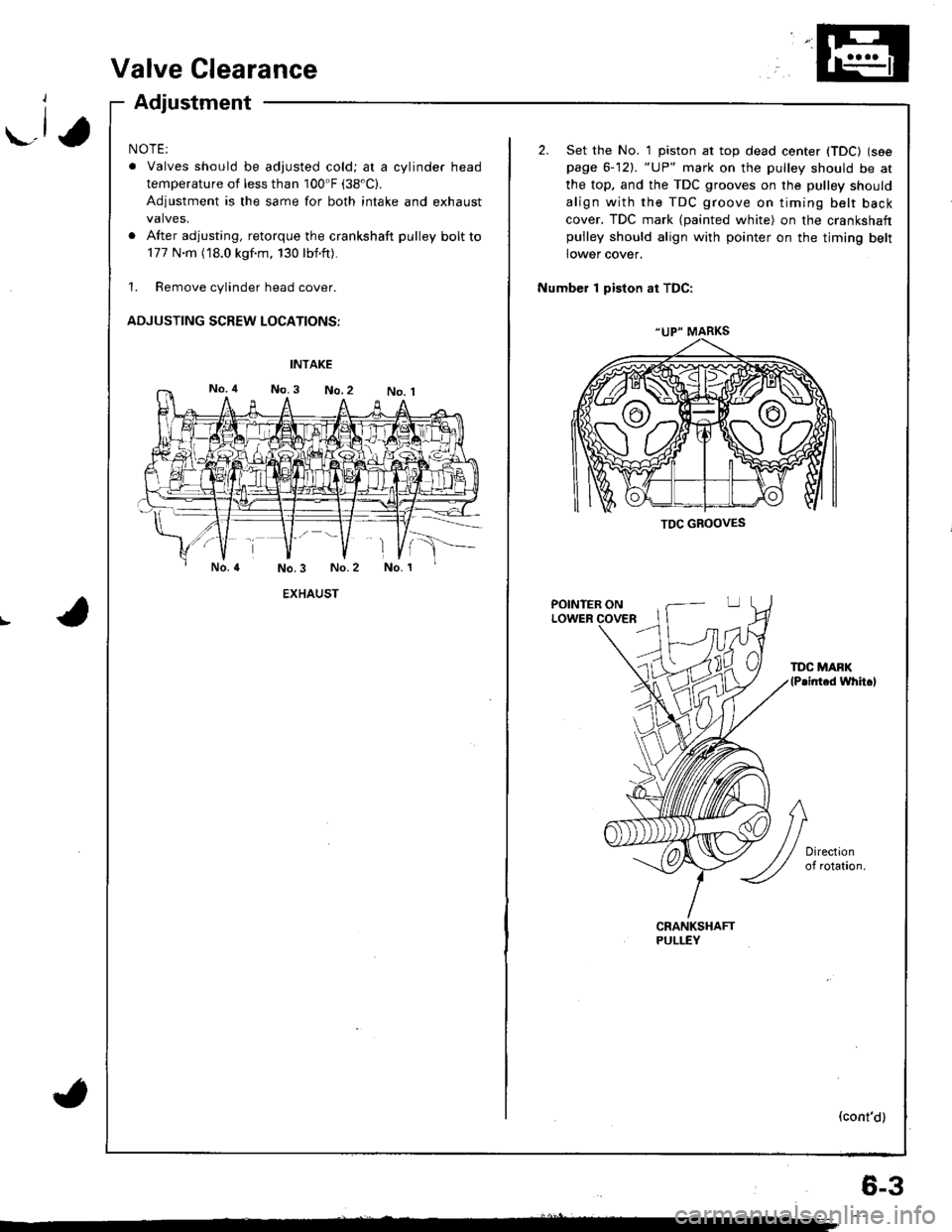
ADJUSTING SCREW LOCATIONS:
EXHAUST
(
"UP" MARKS
TDC GBOOVES
2. Set the No. 1 piston at top dead center (TDC) (see
page 6-12). "UP" mark on the pulley should be at
the top, and the TDC grooves on the pulley should
align with the TDC groove on timing belt back
cover. TDC mark (painted white) on the crankshaftpulley should align with pointer on the timing belt
lower cover.
Number 1 piston at TDC:
POINTER ONLOWER
TDC MAFK(P.inted whh.l
(cont'd)
6-3
Page 65 of 1680
Valve Clearance
Adjustment (cont'dl
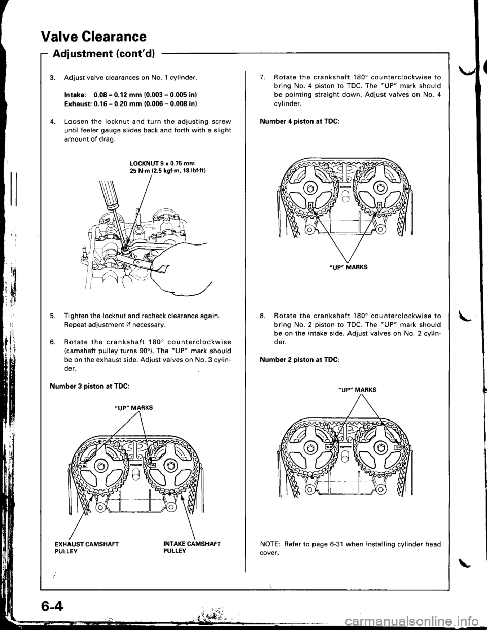
Adjust valve clearances on No. 1 cylinder.
Intske: 0.08 - 0.12 mm (0.003 - 0.005 inl
Exhaust: 0.15 - 0.20 mm (0.006 - 0.008 inl
Loosen the locknut and turn the adjusting screw
until feeler gauge slides back and forth with a slight
amount of drag.
7. Rotate the crankshaft 180' counterclockwise to
bring No. 4 piston to TDC. The "UP" mark should
be pointing straight down. Adjust valves on No. 4
cylinder.
Number 4 piston at TDC:
LOCKNUT9x0.75mm25 N.m {2.5 kgl.m, 18lbtft}
Tighten the locknut and recheck clearance again,
Repeat adjustment if necessary.
Rotate the crankshaft 180' counterclockwise(camshaft pulley turns 90'). The "UP" mark should
be on the exhaust side. Adjust valves on No,3 cylin-
der.
8. Rotate the crankshaft 180' counterclockwise to
bring No. 2 piston to TDC. The "UP" mark should
be on the intake side. Adjust valves on No. 2 cylin-
der.
Number 2 piston at TDC:
Number 3 Diston at TDC:
NOTE: Refer to page 6-31 when installing cylinder head
cover.
"UP" MARKS
"UP" MARKS
"UP" MARKS
Page 68 of 1680
-1,
Timing Belt
lllustrated lndex
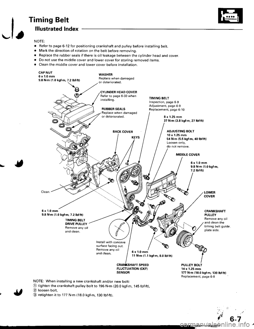
NOTE:
. Refer to page 6-12 for positioning crankshaft and pulley before installing belt.. Mark the direction of rotation on the beh before removing.
. Replace the rubber seals if there is oil leakage between the cylinder head and cover.. Do not use the middle cover and lower cover for storing removed items.. Clean the middle cover and lower cover before installation.
CAP NUT6x1.0mm9.8 N.m {'1.0 kgi.m,
WASHERReplace when damagedor deteriorated.
CYLINDER HEAD COVERRefer to page 6-33 wheninstalling.
RUBBER SEALS
7.2 tbftll
TIMING BELTInspection, page 6 9Adjustment, page 6 9Replacement, page 6,10Beplace when damagedor deteriorated,8 x 1.25 mm37 N.m (3.8 kgf.m, 27 lbf.ft)
BACK COVER
Install with concavesurface facing out.Remove any oiland clean,
ADJUSTING BOLT10 x 1.25 mm54 N.m {5.5 kgt.m, 40 lbf.ltl
MIDDLE COV€R
!6x1.0mm9.8 N.m {1.0 kgf.m,7.2lbl.ftl
6x 1.0mm9.8 N.m 11.0 kgl.m, 7.2lbf.ftl
TIMING BELTDRIVE PULLEYRemove any oilano ctean.
LOWERCOVER
CRANKSHAFTPULLEYRemove any oiland clean thetiming belt guideplate side.
6x1.0mm'11 N.m (1.1 kgf.m, 8.0 lbI.ft)
SPEED
ItEi:lufrroN {cKF)
NOTE: When installing a new crankshaft and/or new bolt:
O tighten the crankshaft pulley bott to 196 N.m (20.0 kgf.m, 145 tbf.ft),
@ loosen bolt,
@ retighten it to 177 N.m (18.0 kgnm, 130 tbnft).
PULLEY EOLT14 x 1.25 mm177 N.m (18.0 kgf.m, 130 bnftlReplacement, page 6-8
6-7
Page 69 of 1680
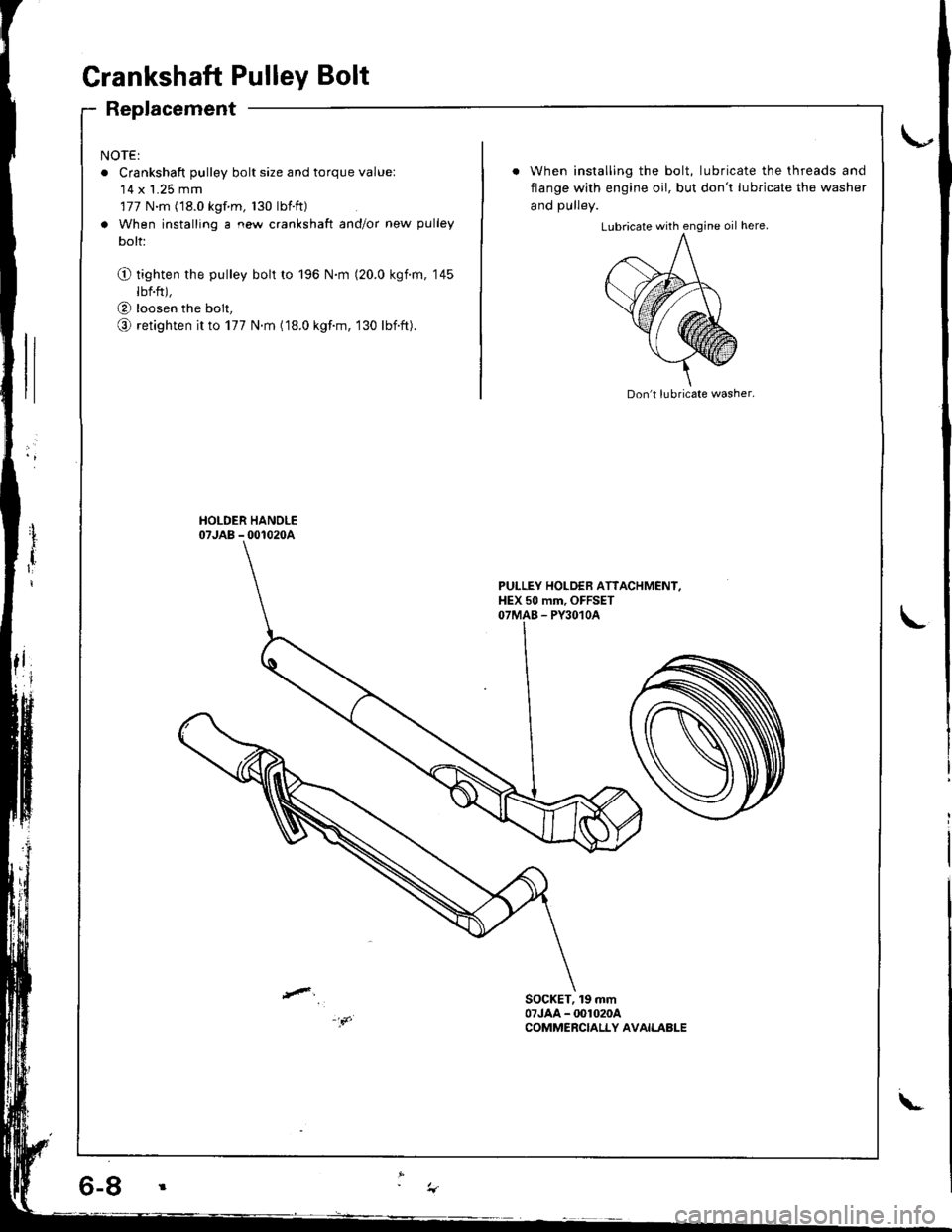
Grankshaft Pulley Bolt
Replacement
NOTE:
o Crankshaft pulley bolt size and torque value:'14 x 1.25 mm
177 N.m (18.0 kgf m, 130 lbtft)
a When installing a new crankshaft and/or new pulley
bolt:
O tighten the pulley bolt to 196 N.m (20.0 kgim, 145
lbf.ft),
@ loosen the bolt,
o retighten it to 177 N.m (18.0 kgf.m, 130 lbift).
When installing the bolt, lubricate the threads and
flange with engine oil, but don't lubricate the washer
and DUllev.
Don't lubricate washer.
PULLEY HOLDEB ATTACHMENI,HEX 50 mm, OFFSETOTMAB - PY3O1OA
SOCKET, 19 mm07JAA - @1020ACOMMERCIALLY AVAILABLE
\-
Page 70 of 1680
\-a
I
I
{
. 6-9
Timing Belt
Inspection
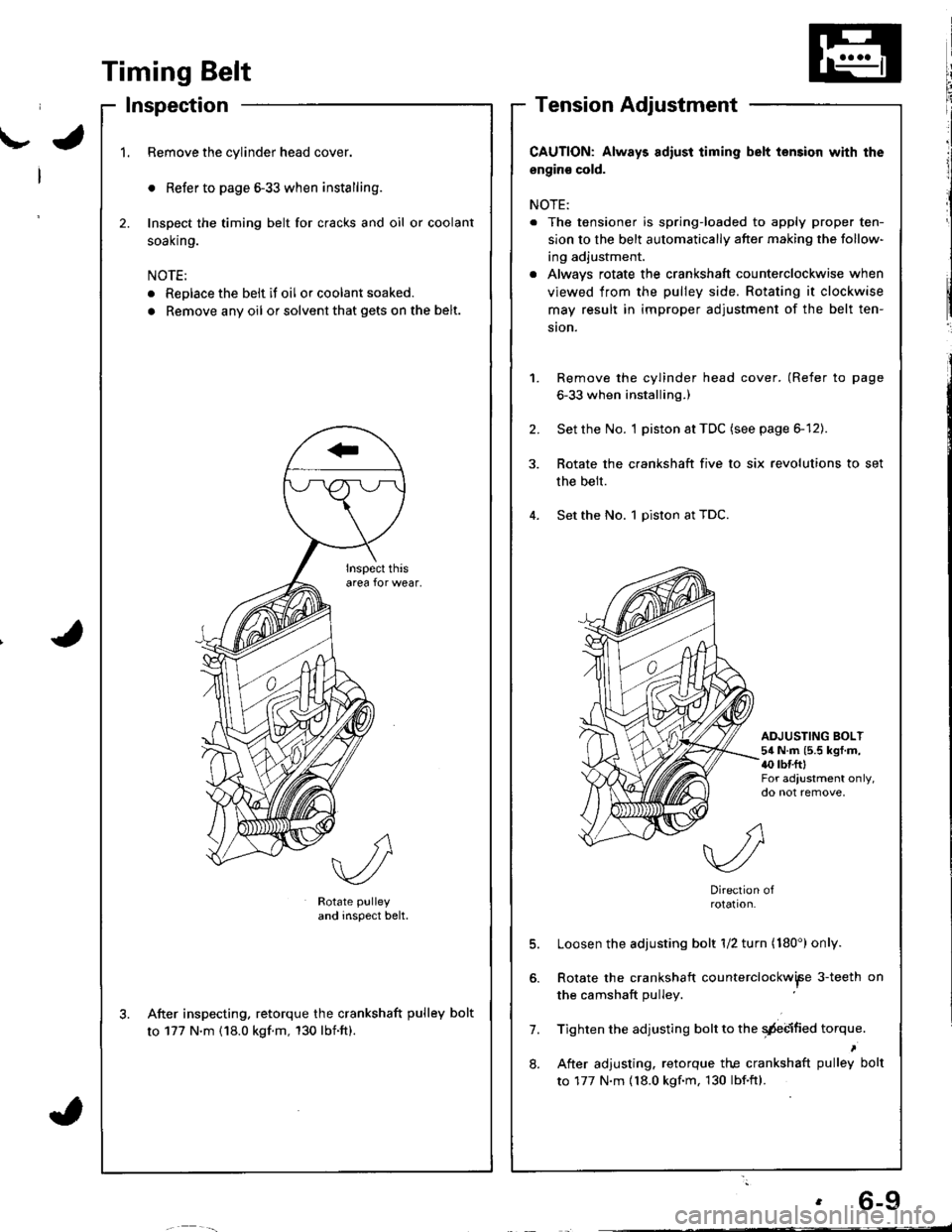
1.Remove the cylinder head cover.
o Refer to page 6-33 when installing.
Inspect the timing belt for cracks and oil or coolant
soal(n9.
NOTE:
. Replace the belt if oil or coolant soaked.
. Remove any oil or solvent that gets on the belt.
2.
Rotate pulley
and inspect belt.
After inspecting. retorque the crankshaft pulley bolt
to 177 N'm (18.0 kgf.m, 130 lbnft).
CAUTION: Always adiust iiming belt lension with the
engin€ cold.
NOTE:
. The tensioner is spring-loaded to apply proper ten-
sion to the belt automatically after making the follow-
ing adjustment.
. Alwavs rotate the crankshaft counterclockwise when
viewed from the pulley side. Rotating it clockwise
may result in improper adjustment of the belt ten-
ston.
Remove the cylinder head cover. (Refer to page
6-33 when installing.)
Set the No. I piston at TDC (see page 6-12).
Rotate the crankshaft five to six revolutions to set
the belt.
Set the No. 1 piston at TDC.
1.
2.
ADJUSTING BOLT54 N.m (5.5 kgf.m,{0 rbr.fttFor adjustment only,do not remove,
7.
8.
Direction ofrotation.
Loosen the adjusting bolt 1/2 turn (180') only.
Rotate the crankshaft counterclockwiFe 3-teeth on
the camshaft pulley
Tighten the adjusting bolt to the qdebified torque.
After adjusting. retorque the crankshaft pulley bolt
to 177 N.m {18.0 kgf.m, 130 lbf.ftl.
Page 81 of 1680
Gylinder Head
Removallcont'd)
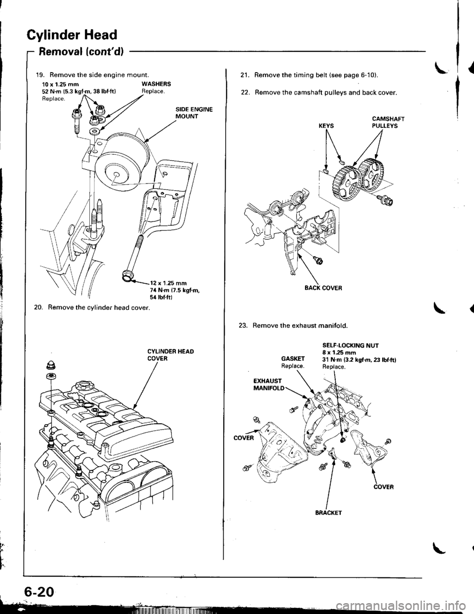
19. Remove the side engine mount.
10 x 1.25 mm52 N.m {5.3 kgt:m, 38 lbl.ft}
20. Remove the cylinder head cover.
SIDE ENGINEMOUNT
12 x 1.25 mm74 N.m 17.5 kgt.m,sil lbtft)
CYLINOER HEADCOVER
t
L
I'
L21.
22.
Remove the timing belt (see page 6- 10).
Remove the camshaft pulleys and back cover.
CAMSHAFTPULLEYS
23. Remove the exhaust manifold.
GASKETReplace.
SELF.LOCKING NUT8 x 1.25 mm3'l N.m 13.2 kgl.m, 23 lbf.ftlReplace.
Page 91 of 1680
Cylinder Head
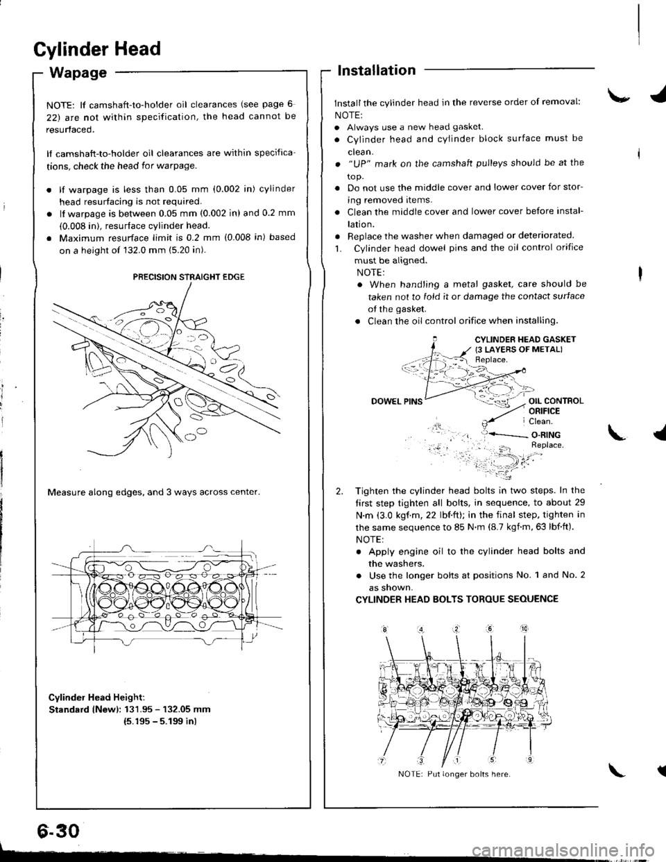
Wapage
NOTE: lf camshaft-to-holder oil clearances (see page 6
22) arc nol within specification, the head cannot be
resurfaced.
lf camshaft-to-holder oil clearances are within specifica-
tions, check the head for warpage.
lf warpage is less than 0.05 mm (0.002 in) cylinder
head resurfacing is not required.
lf warpage is between 0.05 mm (0.002 in) and 0.2 mm
(0.008 in). resurface cylinder head.
Maximum resurface limit is 0.2 mm (0.008 in) based
on a height of 132.0 mm (5.20 in).
Measure along edges, and 3 ways across center.
Cylinder Head Height:
Standard lNewl: 131.95 - 132.05 mm(5.195 - 5.199 inl
lnstallation
Install the cylinder head in the reverse order of removal:
NOTE:
. Always use a new head gasket.
. Cylinder head and cYlinder block surface must be
clean.
. "UP" mark on the camshaft pulleys should be at the
to p.
. Do not use the middle cover and lower cover for stor-
ing removed items.
. Clean the middle cover and lower cover before instal-
lation.
. Replace the washer when damaged or deteriorated
L Cylinder head dowel pins and the oil control orifice
must be aligned.
. When hand'ing a metal gasket, care should be
taken not to fold it or damage the contact surface
of the gasket.
. Clean the oil control orifice when installing,
OIL CONTROLORIFICE
PRECISION STRAIGHT EDGE
6.30
CYLINDER HEAD GASKET
{3 LAYERS OF METAL)
DOWEL
Tighten the cylinder head bolts in two steps. In the
tirst step tighten all bolts, in sequence, to about 29
N.m (3.0 kgf.m,22 lbf.ft); in the final step. tighten in
lhe same sequence to 85 N.m (8.7 kgnm,63 lbf.ft).
NOTE:
. Apply engine oil to the cylinder head bolts and
the washers.
. Use the longer bolts at positions No. 1 and No. 2
as snown,
CYLINDER HEAD BOLTS TOROUE SEOUENCE
\.l
tNOTE: Put longer bolts here.
t-
Page 93 of 1680
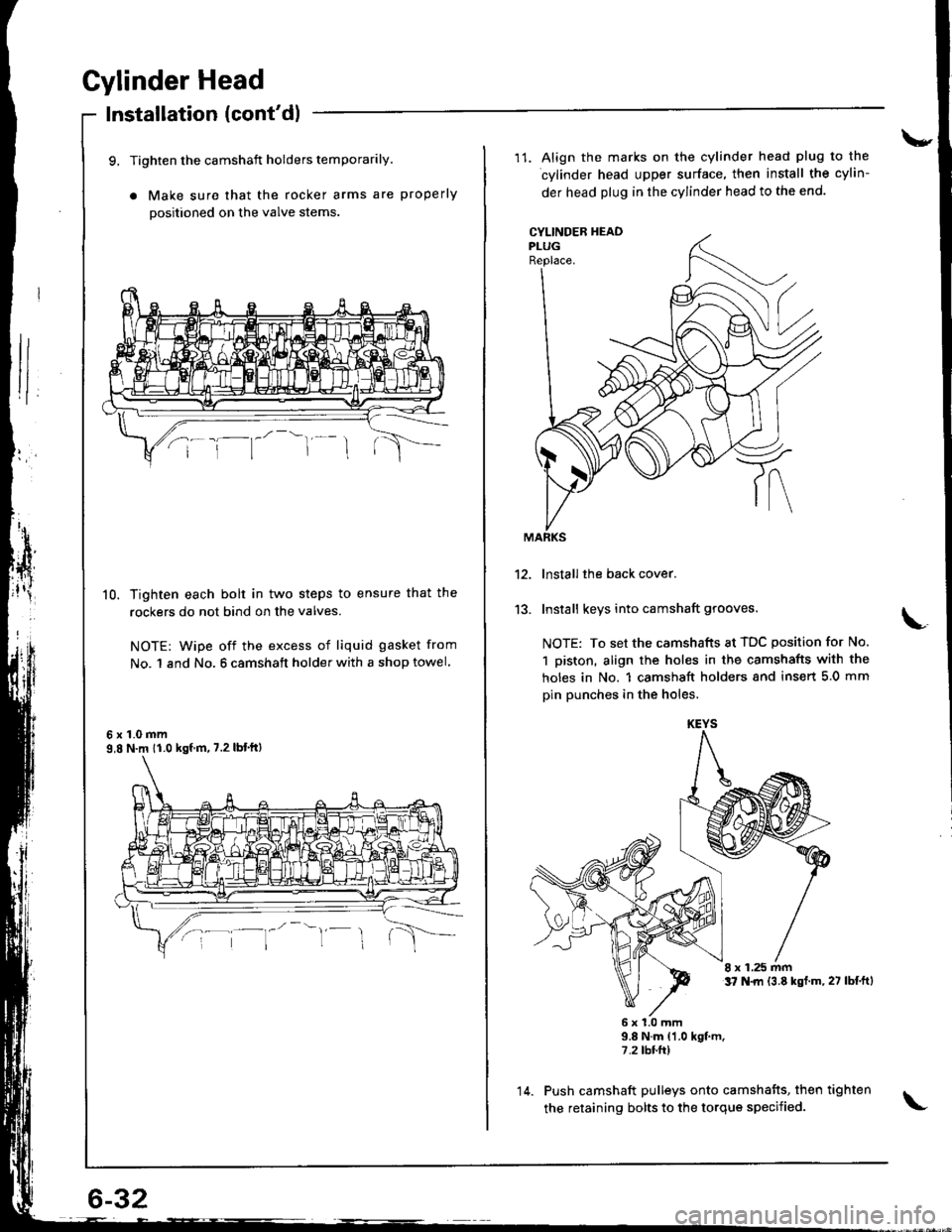
Cylinder Head
Installation (cont'dl
9, Tighten the camshaft holders temporarily.
a Make sure that the rocker arms are properly
positioned on the valve stems
10. Tighten each bolt in two steps to ensure that the
rockers do not bind on the valves.
NOTE: wipe off the excess of liquid gasket from
No. 1 and No. 6 camshaft holder with a shop towel
6x1.0mm9,8 N.m 11.0 kgf m, 7.2 lbt'ftl
\-
11. Align the marks on the cylinder head plug to the
cylinder head upper surface, then install the cylin-
der head plug in the cylinder head to the end.
CYLINDEB HEADPLUGReplace.
13.
lnstall the back cover.
Install keys into camshaft grooves.
NOTE: To set the camshafts at TDC position for No.
1 piston, align the holes in the camshafts with the
holes in No. 1 camshsft holders snd insert 5.0 mm
pin punches in the holes.
8 x 1.25 mmt7 N.|rl {3.8 kst.m,27 lbf.ftl
6x1.0mm9.8 N.m {1.0 kgt m.7.2 tbr.ft)
Push camshaft pulleys onto camshafts, then tighten
the retaining bolts to the torque specified.
KEYS
14.
Page 172 of 1680
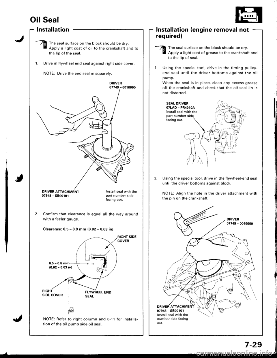
Oil Seal
Installation
The seal surface on the block should be dry.
Apply a light coat of oil to the crankshaft and
the lip of the seal.
1. Drive in tlywheel end seal against right side cover.
NOTE: Drive the end seal in squarely.
DRIVER07749 - 0010000
Confirm that clearance is equal all the way around
with a feeler gaug€.
Clearance: 0.5 - 0.8 mm {0.02 - 0.03 inl
RIGHT SIDECOVER
lnstallation (engine removal not
requiredl
The seal surface on the block should be dry.
Apply a light coat of grease to the crankshaft and
to the lip of seal.
1. Using the special tool, drive in the timing pulley-
end seal until the driver bottoms against the oil
pump.
When the seal is in place, clean any excess grease
off the crankshalt and check that the oil seal lip is
not distoned.
SEAL DRIVER07LAD. PR4O1OAlnstall seal with thepan numberfacing out.
Using the special tool, drive in the flywheel end seal
untilthe driver bottoms aqainst block.
NOTE: Align the hole in the driver attachment with
the pin on the crankshaft.
DRIVER077{9 - 0010000
DRIVER ATT07948 - 5800101lnstall sealwith thenumber side facinqou!.
'tvA,)/ )
DBIVER ATTACHMENT07948 - 5800101Install sealwith thepan number sidefacang out.
[7Fd
NOTE: Refer to right column and 8-11
tion of the oil pump side oil seal.
for installa-