vtec ACURA INTEGRA 1998 Service Repair Manual
[x] Cancel search | Manufacturer: ACURA, Model Year: 1998, Model line: INTEGRA, Model: ACURA INTEGRA 1998Pages: 1680, PDF Size: 53.14 MB
Page 220 of 1680
t;
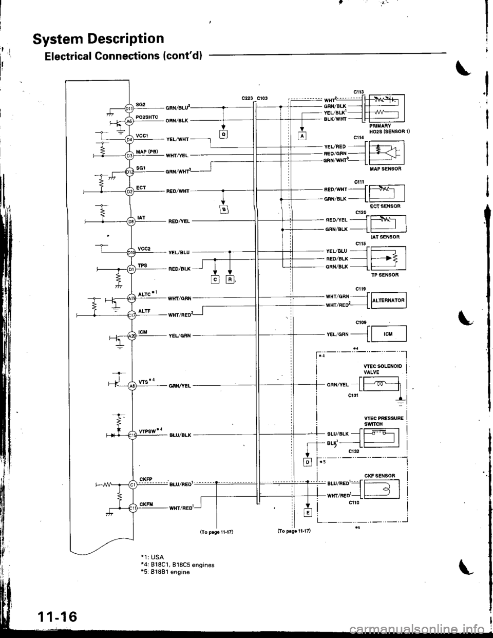
System Description
sG2
Electrical Connections (cont'd)
c223 CiOSi
I
PO2SHTC
vccl
vcc2
cnl6lu'
OFN/BLK
YEVWHT
WHT/YEL
REO/YEL
YEVBLU
RED/ALX
WHI/qFN
TPS
neo,wrtrJffil
oFN/Btx--1-:JECt SE SOR
neonerJf$l
cnvELx--L# |IAT SENSOR
vsveLu--JJr[5lneozgr.x--_l F--? |cnN/Blx 1-:JfP SENSOR
".,.""11--,"u-l
I WECSOLENOIDI VALVE
VTEC PIIESSUFEswtTcH
-+ BLU/BLK - |----o o--l I- +- aq'- --l # |
+ i crdl
fr i-'-
t'=- - -
l
*-,*{Fli
,.,__!i
CXFSEN90B
._.._.._..J
PAI||ARYHO2S (SENSOR 1)cfl4ft'-------------1YEVBED ---l f .g--t- IFEo/cBN ___l F=-< f Icnr,wxr"_ lFj IIIAP SENSOB
cill
*4: 818C1, 818C5 engines*5: 81881 engine
11-16
Page 243 of 1680
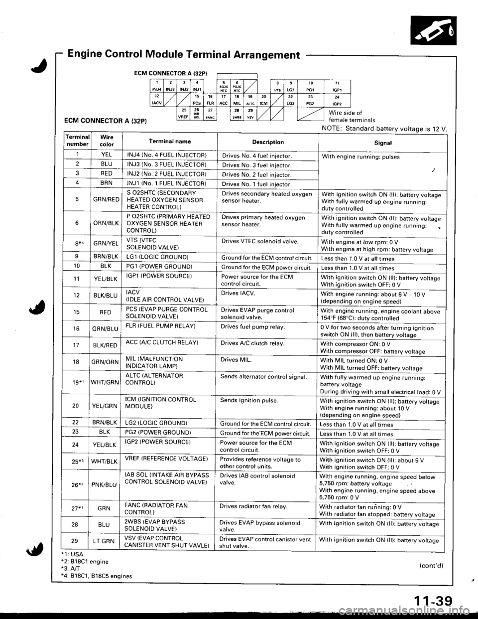
Engine Control Module Terminal Arrangement
ECM CONNECTOR A I32P}
ECM CONNECTOR A I32PI
*1: USA*2:818C1 engine*3:A,/T*4: 818C1, 818C5 engines
female terminals
NOTEr Standard battery voltageis 12 V.
{cont'di
LG22A
TerminalWireTerminal nameDescriptionSignal
YELlNJ4 (No. 4 FUEL INJECTOR)Drives No. 4 fuel iniector.With engine running: pulses2BLUlNJ3 (No.3 FUEL INJECTOR)Drives No. 3 fuel injector.
3REDlNJ2 (No.2 FUEL INJECTOB)Drives No.2 fuel injector.
BRNlNJl (No. 1 FUEL INJECTOR)Drives No. l Iuel iniector.
5GRN/REDS 02SHTC (SECONDARY
HEATED OXYGEN SENSORHEATER CONTROL)
Drives secondary heated oxygensensor heater,With ignition switch ON (ll)i battery volrageWith fully warmed up engine runningiduty controlled
6ORN/BLKP O2SHTC {PRIMARY HEAIEDOXYGEN SENSOB HEAIERCONTFOL)
Draves primary heated oxygensensor heater,With ignition swirch ON (ll): battery voltageWith lully warmed up engine running:duty controlled
84G RNI/ELVTS (VTEC
SOLENOID VALVE)Drives VTEC solenoid valve.With engine at low rpm: 0 VWith engine at high rpm: battery voltageIBRN/BLKLG1 (LOGIC GROUND)Ground for the ECM control circuit.Less than 1.0 V at alltimes10BLKPGl (POWER GROUND)Ground for the EC[, power circuit.Less than 1.0 V at all times't'lYEUBLKIGPl {POWER SOURCE)Power source for the ECMcontrolcircuit.With ignition switch ON 1ll): battery voltageWith ignition switch OFF| 0 V
12BLI(8LUIACV(IDLE AIR CONTROL VALVE}Drives IACV.With engine running: about 6 V 10 V(depending on engine speed)
REDPCS (EVAP PURGE CONTROLSOLENOID VALVE)Drives EVAP purge controlsolenoid valve.Wilh engane running, engine coolant above154"F (68'C): duty controlled
GRN/BLUFLR (FUEL PUMP RELAY)Drives fuel pump relay.0 V for two seconds after turning ignitionswitch ON (ll), then battery voltage
17B LVBEDACC (fuC CLUTCH RELAY)Drives A,/C clulch relay.With compressor ON: 0 VWith compressor OFFt baftery voltage
18GRN/ORNMIL (I\4ALFUNCTION
INDICATOR LAMPiDrives MlL.With MIL turned ON:0 VWjth MIL turned OFF: battery vottage
19*,WHT/GRNALTC (ALTERNATOR
CONTROL)Sends alternator control signal,With fully warmed up engine runninglbattery voltageDuring driving with small electrical load: 0 V
20YEUGRNICM (IGNITION CONTROLMODULE)Sends ignition pulse.With ignition switch ON (ll): battery voltageWith engine running: about'10 V(depending on engine speed)22BRN/BLKLG2 (LOGIC GROUND)Ground forthe ECM controlcifcuit.Less than 1.0 V at all times8LKPG2 (POWEfl GROUND)Ground for the ECM power circuit.Less than 1.0 V at all times
24YEUELKIGP2 (POWER SOURCE)Power source for the ECMcontrolcircuit,With ignition switch ON {lli: battery voltageWith ignition switch OFF: 0 V
25*3WHT/BLKVREF (REFERENCE VOLTAGE)Provides reference voltage toother control units,With ignition swirch ON (ll): about 5 VWath ignition switch OFF: 0 V
26. 'PNK/8LU
IAB SOL (INTAKE AIR BYPASSCONTROL SOLENOID VALVE)Drives IAB conlrol solenoidWith engrne running, engrae speed betow5,750 rpm: battery voltageWith engine running, engine speed above5,750 rpm: 0 V
27* IGRNFANC (BADIATOR FANCONTROL)Drives radiator fan relay.With radiator {an running: 0 VWith radiator Ian stopped: battery voltage
2ABLU2WBS (EVAP BYPASSSOLENOID VALVE)Drives EVAP bypass solenoidWith ignition switch ON (ll): battery vottage
29LT GRNVSV (EVAP CONlROLCANISTER VENT SHUT VAVLE)Drives EVAP control canister ventshut valve.Wilh ignilion switch ON lll): banery votrasc
1 1-39
Page 244 of 1680
I
t
h,,l,!
il
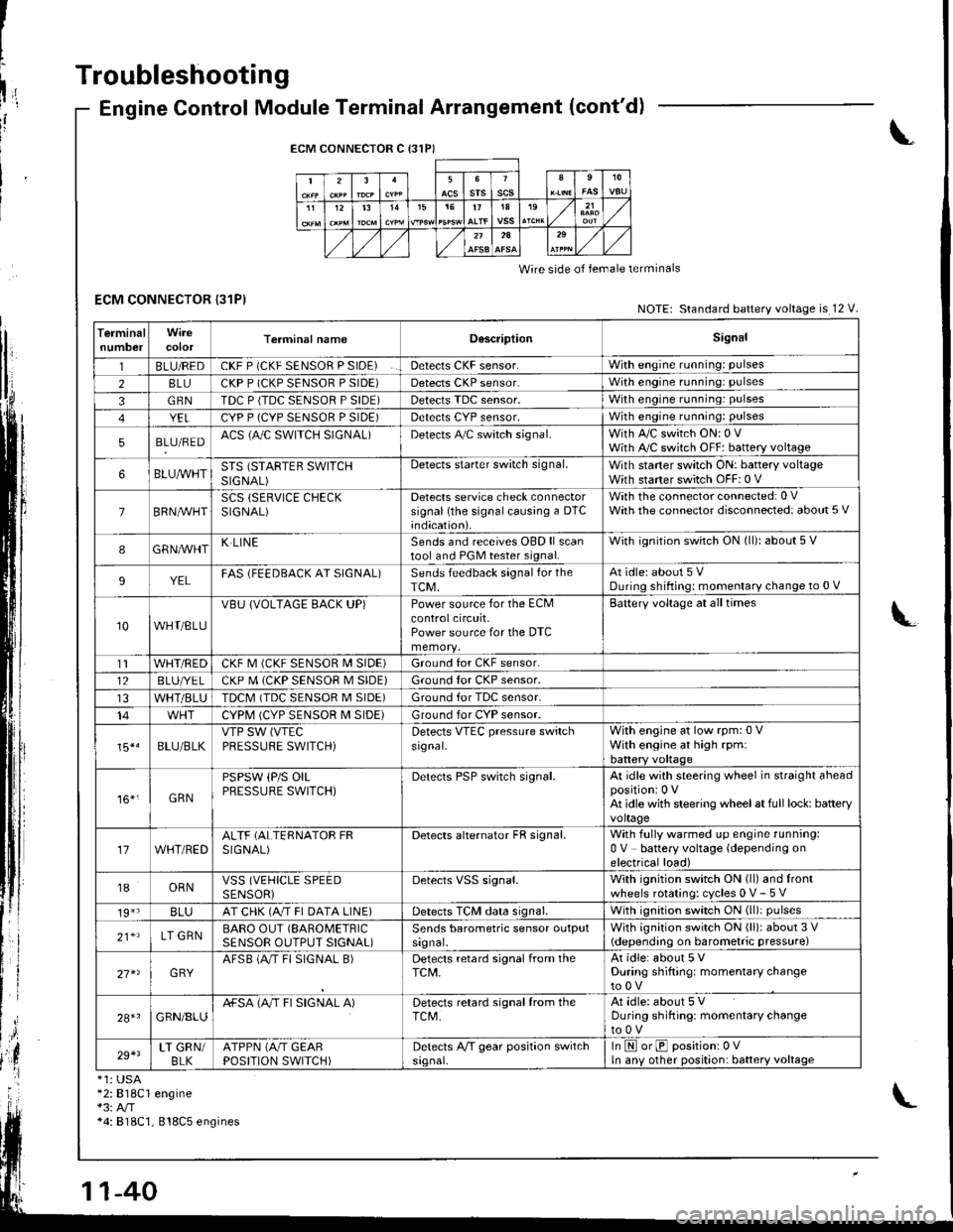
Troubleshooting
ECM CONNECTOR {31P)
Engine Control Module Terminal Arrangement (cont'd)
ECM CONNECTOR C {31P)
235srsscs1112t31515t71A19
2A
Wire side of lemale terminals
NOTE: Standard battery voltage is 12 V.
TerminalnumbercolorTerminal namoD6scriptionSignal
1BLU/REDCKF P (CKF SENSOR P SIDE)Detects CKF sensor.With engine running: pulses
28LUCKP P (CKP SENSOR P SIDE)Detects CKP sensor.With engine running: pulses
3GRNTDC P {TDC SENSOR P SIDE)Detects TDC sensor,With engine running: pulses
YELCYP P (CYP SENSOR P SIDE)Detects CYP sensor,With engine running: pulses
5BLU/REDACS (AJC SWITCH SIGNAL)Detects A,/C switch signal.With A,/C switch ON: 0 VWith A,/C switch OFF: battery voltage
6BLUA/VHTSTS (STARTEB SWITCHSIGNAL)
Detects starter switch signal.With staner switch ON: battery voltageWith starter switch OFF: 0 V
7BRN,AiVHTSCS (SERVICE CHECKSIGNAL)Detects service check connectorsignal (the signalcausing a DTC;ndication).
With the co n nector con nected: 0 VWath the connector disconnected: about 5 V
8GRNAVHTK LINESends and receives OBD ll scantool and PGM tester signal.With ignition switch ON (ll): about 5 V
9YELFAS lFEEDBACK AT SIGNAL)Sends feedback signal for theTCM,At idle: about 5 VDuring shifting: momenlary change to 0 V
10WHT/BLU
VBU (VOLTAGE BACK UP)Power source for the ECMcontrolcircuit,Power source for the DTC
Battery voltage at all times
t1WHT/REDCKF M (CKF SENSOR I\4 SIDE)Ground for CKF sensor.
12BLUI/E LCKP M (CKP SENSOR M SIDE)Ground for CKP sensor.
WHT/BLUTDCM (TDC SENSOR M SIDE)Ground tor TDC sensor.
14CYPM (CYP SENSOR M SIDE)Ground for CYP sensor.
15*.BLU/BLKVTP SW (VTEC
PRESSUFE SWITCH)Detects VTEC pressure switchsr9nal.
With engine at low rpm:0 VWith engine at high rpmlbattery voltaqe
161,GRN
PSPSW (P/S OILPRESSURE SWITCH)Derecls PSP switch signal.At idle with steering wheel in straight aheadpositioni 0 VAt idle with steering wheelat full lock: batteryvoltage
17WHT/REDALTF (ALTERNATOR FRSIGNAL)Detects alternator FR signal.With fully warmed up engine running:0 V battery voltage (depending onelectrical load)
18ORNVSS (VEHICLE SPEEDSENSORiDetects VSS signal.With ignition switch ON (ll) and lrontwheels rotating: cycles 0 V- 5 V
19*3BLUAT CHK (A/T FI DATA LINE)Detects TCM data signal.With ignition switch ON (ll)i pulses
21*LT GRNBARO OUT (SAROMETRIC
SENSOR OUTPUT S!GNAL)Sends barometric sensor outputsrgnal,With ignition switch ON (ll): about 3 V(depending on barometric pressure)
27 x3GRYAFSB (A"/T FI SIGNAL B)Detects retard signal from theTCM,At idle: about 5 VDuring shifting: momentary changeto0V
28+1GRN/8LUA+SA (A/T FI SIGNAL A)Detects retard signal from theTCM.At idle: about 5 VDuring shifting: momentarV changeto0V
29+3LT GRN/BLKATPPN (A/T GEARPOSITION SWITCH)Detects A,/T gear position switchsrgnal-In E orE positionr 0VIn anv other position: battery voltage
*1: USA*2:818C1 engine*3: A/T*4: 818C1, 818C5 engines
Page 248 of 1680
Troubleshooting
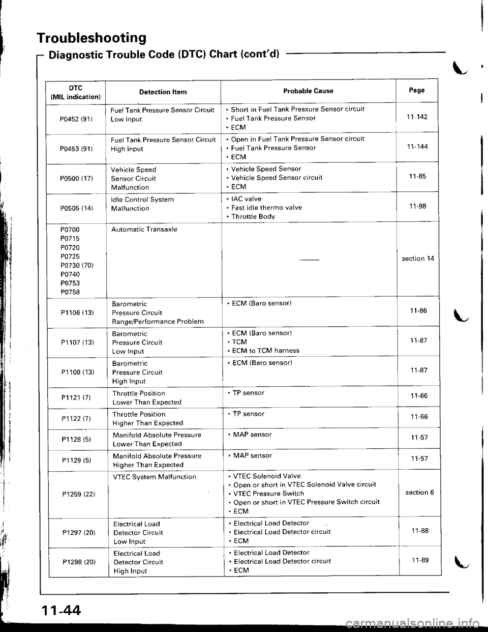
Diagnostic Trouble Code (DTCI Chart (cont'd)
L
DTC
(MlL indication)Detection ltemProbable CausePage
P0452 (91)FuelTank Pressure Sensor Circuit
Low lnput
Short in Fuel Tank Pressure Sensor circuit
Fuei Tank Pressure Sensor
ECM
11 142
P0453 (91)Fuel Tank Pressure Sensor Circuit
High Input
Open in Fuel Tank Pressure Sensor circuit
Fuel Tank Pressure Sensor
ECrVI
11-144
P0500 {17}
Vehicle Speed
Sensor Circuit
Malfunction
Vehicle Speed Sensor
Vehicle Speed Sensor circuit
ECM
11-85
P0505 (14)ldle Control System
Malfunction
IAC valve
Fast idle thermo valve
Th rottle Body
'11-98
P0700
P0715
P0120
P0125
P0730 (70)
P0740
P0753
P0758
Automatic Transaxle
section'14
Pl106 (13iBarometric
Pressure Circuit
Range/Performance Problem
. ECM (Baro sensor)1'l -86
P1107 ('�]3)Barometric
Pressure Circuit
Low lnput
ECM (Baro sensor)
TCM
ECM to TCM harness
11-87
P1'108 (13)Ba ro metric
Pressure Circuit
High Input
ECM (Baro sensor)11-41
P1121 \11Throttle Position
Lower Than Expected
. TP sensor
P112211JThrottle Position
H igher Than Expected
'TP sensor
P1 '�t 28 (5)Manifold Absolute Pressure
Lower Than Expected
. MAP sensor11,57
P1129 (5)Manilold Absolute Pressure
Higher Than Expected
. MAP sensor11-57
P1259 \22)
VTEC System MalfunctionVTEC Solenoid Valve
Open or short in VTEC Solenoid Valve circuit
VTEC Pressure Switch
Open or short in VTEC Pressure Switch circuit
ECM
section 6
P1297 (20)Electrical Load
Detector Circuit
Low Input
Electrical Load Detector
Electrical Load Detector circuit
ECM
11-88
P1298 (20)Electrical Load
Detector Circuit
Hig h Input
Electrical Load Delector
Electrical Load Detector circuit
ECM
11-89
-44
Page 252 of 1680
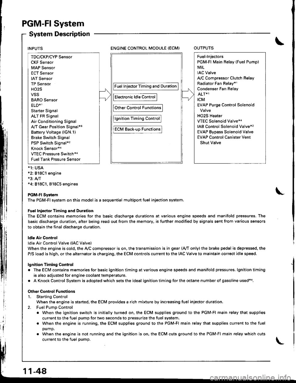
PGM-FI System
System Description
ENGINE CONTROL MODULE (ECM)OUTPUTS
*1: USA*2: 818C1 engine*3: A,/T*4: 818C1, 818C5 engines
PGM-FI Sy3tem
The PGM-Fl system on this model is a sequential multiport fuel injection system.
Fuel lniector Timing and Duration
The ECM contains memories for the basic discharge durations at various engine speeds and manifold pressures. The
basic discharge duration, after being read out from the memory. is further modified by signals sent from various sensors
to obtain the final discharge duration.
ldle Air Control
ldle Ai. Control Valve (lAC Valve)
When the engine is cold, the Ay'C compressor is on. the transmission is in gear (Ay'T only)the brake pedal is depressed, the
P/S load is high, or the alternator is charging, the ECM controls current to the IAC Valve to maintain correct idle speed.
lgnition Timing Control
. The ECM contains memories for basic ignition timing atvarious engine speeds and manifold pressures, lgnitiontiming
is also adjusted for engine coolant temperature.
. AKnockControl System isadoptedwhich sets the ideal ignition timing for the octane n um ber of gasoline used*r,
Other Control Functions
L Starting Control
When the engine is started, the ECM provides a rich mi{ure by increasing fuel injector duration.
2. Fuel PumD Control
. When the ignition switch is initially turned on, the ECM supplies ground to the PGM-FI main relay that supplies
current to the fuel pump for two seconds to pressurize the fuel system.
. When the engine is running, the ECM supplies ground to the PGM-FI main relay that supplies current to the fuel
DUmO.
. When the engine is not running and the ignition is on. the ECM cuts ground to the PGM-FI main relay which cuts
current to the fuel oumo.
INPUTS
TDc/CKP/CYP Sensor
CKF Sensor
MAP Sensor
ECT Sensor
IAT Sensor
TP Sensor
HO2S
VSS
BARO Sensor
ELD*1
Starter Signal
ALT FR Signal
Air Conditioning Signal
A,/T Gear Position Signal*3
Battery Voltage (lGN.1)
Brake Switch Signal
PSP Switch Signal*'�
Knock Sensor*1
VTEC Pressure Switch*4
Fuel Tank Prssure Sensor
Fuel InjectorTiming and Duration
Electronic ldle Control
Other Control Functions
lgnition Timing Control
ECM Back-uD Functions
Fuel-lnjectors
PGM-Fl Main Relay (Fuel Pump)
MIL
IAC Valve
A,/C Compressor Clutch Relay
Radiator Fan Belay*1
Condenser Fan Relay
ALT*1
rcM
EVAP Purge Control Solenoid
Valve
H02S Heater
VTEC Solenoid Valve*'
IAB Control Solenoid Valve*,
EVAP Bypass Solenoid Valve
EVAP Control Canister Vent
Shut Valve
11-48
Page 280 of 1680
PGM-Fl System
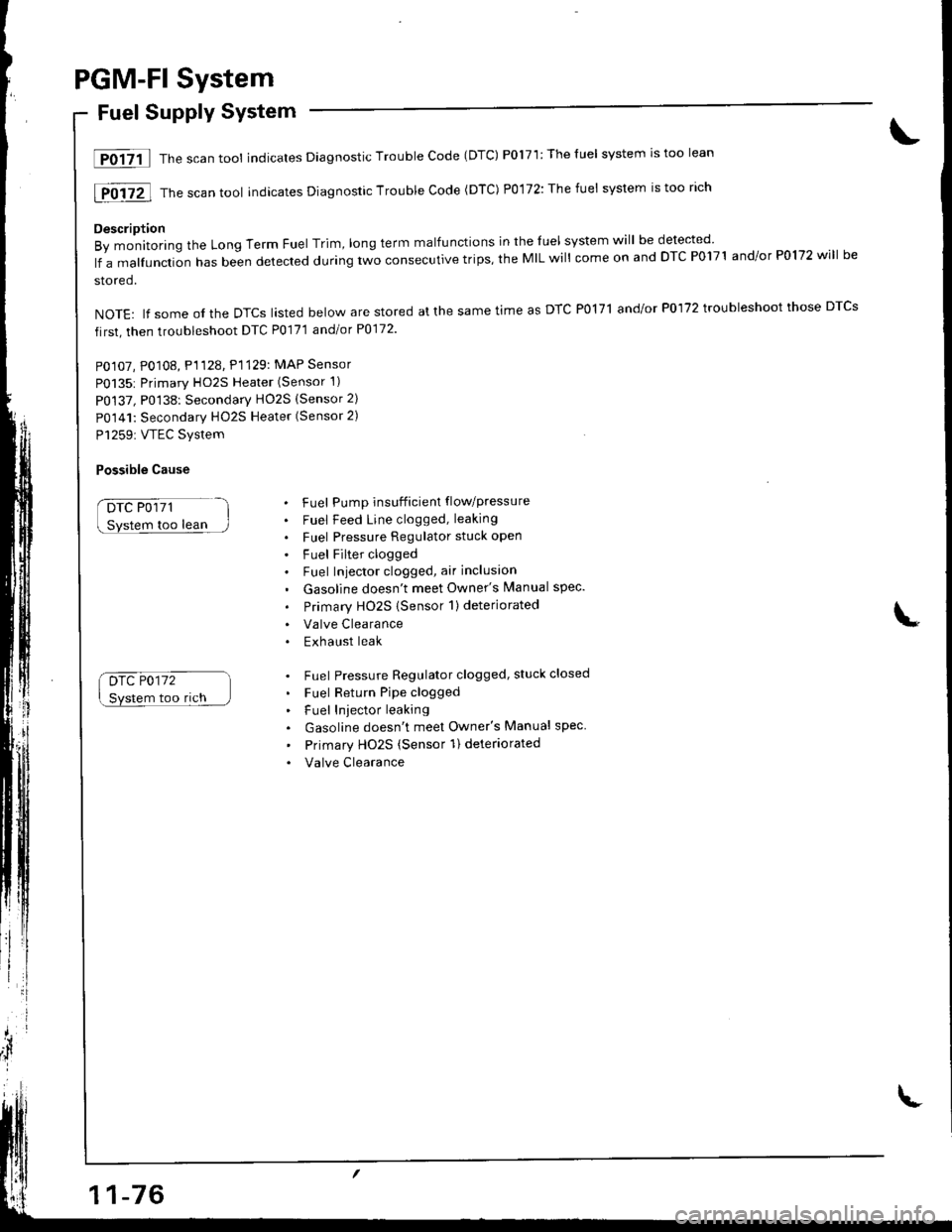
Fuel Supply System
lF0{7il Thescantool indicates Diagnostic Trouble Code (DTC) P0171:Theluel system rstoo lean
[F0i72l Th" ""un tool indicates Diagnosric Trouble code (DTc) p0,172: The fuet system is too rich
Description
By monitoring the Long Term Fuel Trim, long term malfunctions in the luel system will be detected
lf a malfunction has been detected during two consecutive trips, the MIL will come on and DTC P0171 and/or P0172 will be
stored.
NOTE: lf some ol the DTCS lasted below are stored at the same time as DTC PolTl and/or P0172 troubleshoot those DTCS
first, then troubleshoot DTC P0171 andlot P0172
PO107, P0108, P1128. P1129: MAP Sensor
P0135: Primary HO2S Heater (Sensor 1)
P0137, P0138: Secondarv HO2S (Sensor 2)
P0141: Secondary HO2S Heater (Sensor 2)
P1259: VTEC Svstem
Possible Cause
DTC P0171
too lean
Drc P0172
Svstem too rich
. Fuel Pump insufficient flowpressure
. Fuel Feed Line clogged, leaking
. Fuel Pressure Regulator stuck open
. Fuel Filter clogged. Fuel Iniector clogged, air inclusion
. Gasoline doesn't meet Owner's Manual spec.
. Primary HO2S (Sensor 1)deteriorated
. Valve Clearance. Exhaust leak
. Fuel Pressure Regulator clogged, stuck closed
. Fuel Return Pipe clogged
. Fuel Iniector leaking
. Gasoline doesn't meet Owner's Manual spec
' Primary Ho2s (Sensor 1) deteriorated
. Valve Clearance
Page 282 of 1680
PGM-FI System
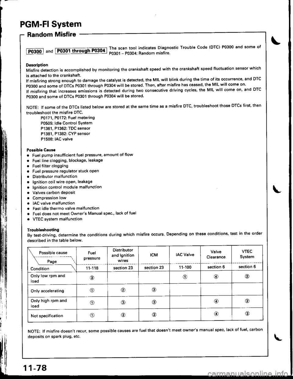
Random Misfire
1T0-500 1 a nd Fo-30ittrrousFF0304-lThB scan tool indicates Diagnostic Trouble Code {DTC) P0300 and some of
P0301 - P0304: Random misfire.
Doscription
Misfir; detection is accomplished by monitoring the crankshaft speed with the crankshaft speed fluciuation sensor which
is attached to the crankshsft.
lf misfiring strong enough to damage the catalyst is detected, the MIL will blink during iho time of its occurrence, and DTC
p0300 and some of DTCS p0301 through P0304 will be stor€d. Then, after misfire has ceased, the MIL will come on.
lf misfiring that increases emissions is detected during two consecutive driving cycles, the MIL will come on, and DTC
PO3O0 and some ot DTCS P0301 through P0304 will be stored
NOTE: lJ some of the DTCS listed below are stored at the same time as a misfire DTC, troubleshoot those DTCS first. then
troubleshoot the misfire DTC.
P0171, P0172: Fuel metering
P0505: ldle Control SYstem
P1361, P1362: TDC sensor
P1381. P1382: CYP sensor
P1508: IAC valve
Possible Cause
. Fuel pump insufficient fuel pressure. amount of flow
. Fuel line clogging, blockage, leakage
. Fuel {ilter clogging
a Fuel pressure regulator stuck open
. Distributormallunction
o lgnition coil wire open, leakage
. lgnition control module malfunction
. Valves carbon deposit
a Compression low
. IAC valve malfunction
. Fast idle thermo valve malfunction
o Fuel does not meet Owner's Manual spec., lackotfu€l
. VTEC system malfunction
Troubleshooting
By test-driving, determine the conditions during which misfire occurs. Depending on these conditions, test in the order
described in the table below.
Fuel
pressure
Distributor
and lgnition
wires
tcMIAC ValveValve
Clearance
wEc
System
11118section 23section 231 1- 100section 6section 6
Only low rpm and
loao@o@@
Only acceleratingo@o
Only high rpm and
loado@@@o
Not specificationo@@@@
NOTE: lf misfire doesn't recur, some possible causes arefuel that doesn't meet owner's manual spec, lackoffuel, carbon
deposits on spark plug, etc.
11-78
Page 981 of 1680
,'t
il
ii
II
APPLICATIONTAPEDOHC VTEC (GSR'
Special Edition {USA LS-S)EMBLEM
REAR TURNSIGNAL LIGHT
APPLICATIONTAPEOUTERTAILLIGHT
J
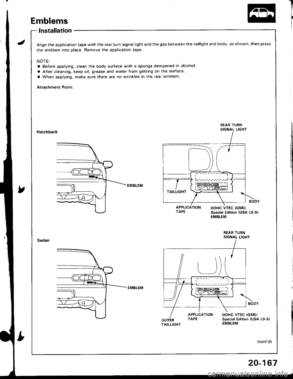
Emblems
lnstallation
Align the application tape with the rear turn signal light and the gap between the taillight and body, as shown, then press
the emblem into place. Remove the application tape.
NOTE:
a Before applying, clean the body surlace with a sponge dampened in alcohol.
a Atter cleaning, keep oil, grease and water trom getting on the surface.
a When applying, make sure there are no wrinkles in the rear emblem
Attachment Point:
Hatchback
REAR TURNSIGNAL LIGHT
DOHC VTEC {GSR)/sDecial Edition lUsa Ls-s)EMBLEM
20-167
Page 1074 of 1680

Connector ldentification and Wire Harness Routing
Engine Wire Harness (B18Cl enginel
Connectol ol
Terminal
Number of
CavitiesLocationConnects toNotes
c 101
c102
c103
c104
c105
c106
c101
c108
cr09
c110
c'r 11
cl12
c1't3
c114
c115
c116
cl17
c118
c119
c119
c120
cI2'l
cl24
c126
c127
cl31
c132
c133
c134
10
14
3
1
2
1
2
10
2
'I
3
2
2
2
I
1
2
2
?
3
2
14
Right side of engine compartment
Right side of engine compartment
Right side of engine compartment
Right side ol engine compartment
Right side of engine compartment
Righr side oI engine
Right side of engine
Transmission
Middle of engine
Middle of engine
Right side of engine
Right side of engine compartment
Middle rear of engine compartment
Middle of engine
Middle of engine
Middle of engine
Middle of engine
i/iddle of engine
Left side ot engine
Lelt side ot engine
Middle ot engine
Middle of engine
Middle of engine
Middle of engine
Middle of engine
Left side of engine companment
Left side of engine compartment
Lelt side of engine compartment
Right side of engine
Right side of engine
Middle of engine
Middle of engine
lvlain wire harness (C221 )
Main wire harness {C222)
Main wire harness (C223)
Main wire harness (C220)
Starter solenoid
Engine coolant temperature (ECT)
sensor
Engine coolant temperature (ECT)
gauge sending unit
Back-up light switch
Distributor
Crankshalt speed fluctuation (CKFI
sensor
Engine coolant temperature {ECT)
switch
Vehicle speed sensor (VSS)
Primary HO2S
MAP sensor
Throttle position {TP) sensor
ldle air control (lAC) valve
EVAP purge control solenoid valve
Engine oil pressure switch
Alternator
Alternator
Intake air temperature llAT) sensor
No. 1 fuel injector
No. 2 fuel injector
No. 3 tuel injector
No. 4 tuel injector
Junctron connector
Engine compartment wire harness(c304)
Engine companment wire harness(c30s)
VTEC solenoid valve
VTEC oil pressure switch
Knock sensor (KS)
Intake air bypass {lAB) control sole-
noid valve
USA
Canada
T101
r 102
Left side ot engine
Right side of engine compartment
Alternator
Under-hood fuse/relay box
G 101Right side of engineEngine ground, via engine wire
naaness
23-18
Page 1599 of 1680
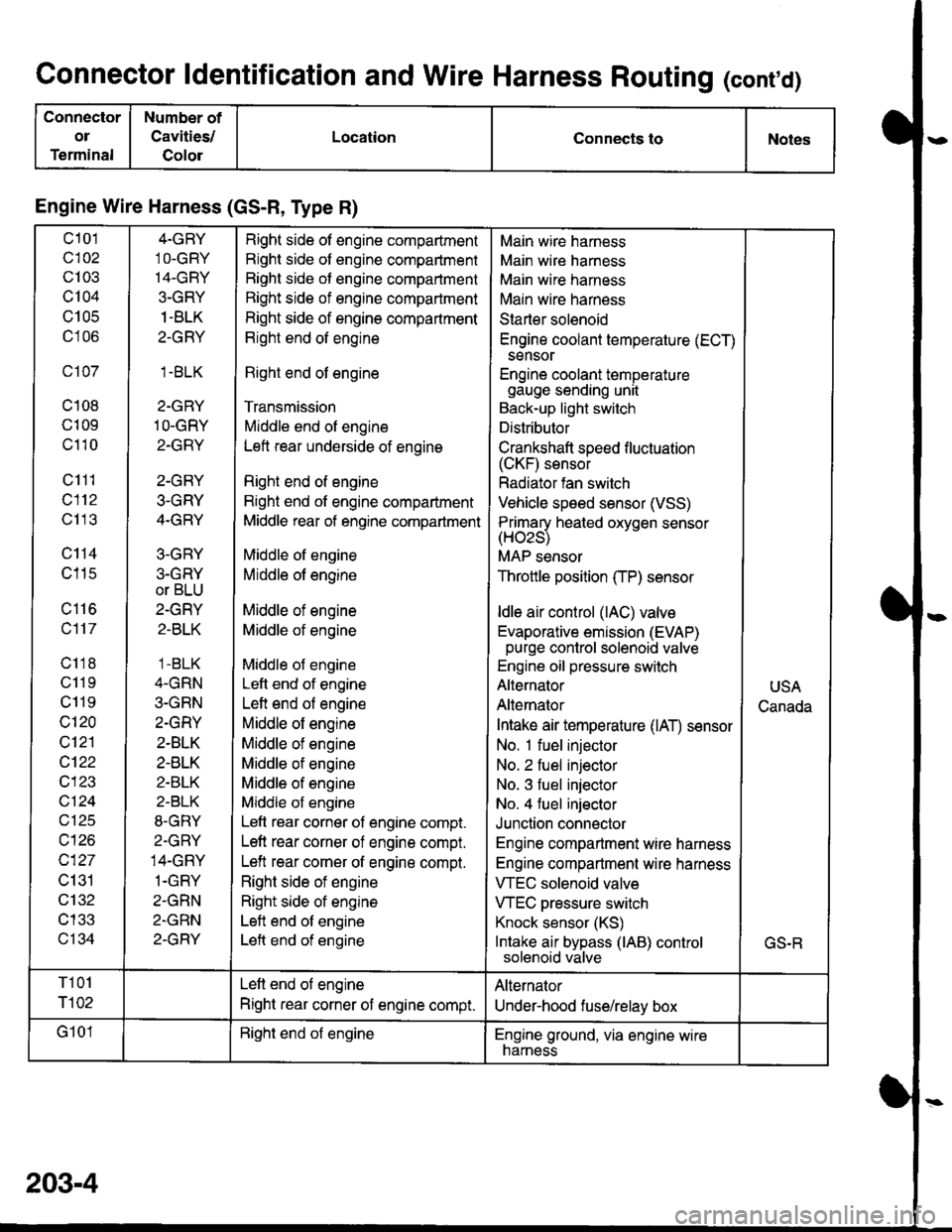
Connector ldentification and Wire Harness Routing (conrd)
Connector
ol
Terminal
Number of
Cavities/
Golor
LocationConnects toNotes
Engine Wire Harness (GS-R, Type R)
c101
c102
c103
c104
U IUC
c106
c107
c108
c109
c110
c111
c112
c113
c114
c115
c116
c117
c118
c11 9
c119
c120
c121
cl22
c123
vtzl
wt10
c127
c131
c132
c133
c134
4-GRY
1O-GRY'I4-GRY
3-GRY
1 -BLK
2-GRY
1.BLK
2-GRY
1O-GRY
2-GRY
2-GRY
3-GRY
4-GRY
3-GRY
3.GRY
or BLU
2-GRY
2-BLK
1 -BLK
4-GRN
3-GRN
2.GRY
2-BLK
2-BLK
2-BLK
2-BLK
8-GRY
2.GRY
14-GRY
1-GRY
2-GRN
2-GRN
2-GRY
Right side of engine compartment
Right side of engine compartment
Bight side of engine compartment
Right side of engine compartment
Right side of engine compartment
Right end of engine
Right end of engine
Transmission
Middle end of engine
Left rear underside of engine
Right end of engine
Right end of engine compartment
Middle rear of engine compartment
Middle of engine
Middle of engine
Middle of engine
Middle of engine
Middle of engine
Left end of engine
Left end of engine
Middle of engine
Middle of engine
Middle of engine
Middle of engine
Middle of engine
Left rear corner of engine compt.
Left rear corner of engine compt.
Left rear corner of engine compt.
Right side of engine
Right side of engine
Left end of engine
Left end of engine
Main wire harness
Main wire harness
Main wire harness
Main wire harness
Starter solenoid
Engine coolant temperature (ECT)
sensor
Engine coolant temperaturegauge sending unit
Back-up light switch
Distributor
Crankshaft speed f luctuation(CKF) sensor
Radiator fan switch
Vehicle speed sensor (VSS)
Primarv heated oxvoen sensor(Hozs)
MAP sensor
Throttle position (TP) sensor
ldle air control (lAC) valve
Evaporative emission (EVAP)purge control solenoid valve
Engine oil pressure switch
Alternator
Alternator
Intake air temperature (lAT) sensor
No. 1 fuel injector
No. 2 fuel injector
No. 3 fuel injector
No. 4 fuel injector
Junction connector
Engine compartment wire harness
Engine compartment wire harness
VTEC solenoid valve
VTEC pressure switch
Knock sensor (KS)
Intake air bypass (lAB) controlsolenoid valve
USA
Canada
GS.R
T101
r102
Left end of engine
Right rear corner of engine compt.
Alternator
Under-hood fuse/relay box
G101Right end of engineEngine ground, via engine wirenarness
203-4