water pump ACURA INTEGRA 1998 Service Repair Manual
[x] Cancel search | Manufacturer: ACURA, Model Year: 1998, Model line: INTEGRA, Model: ACURA INTEGRA 1998Pages: 1680, PDF Size: 53.14 MB
Page 194 of 1680
Cooling
lllustrated Index ........
Radiator
Replacement ..............
Engine Coolant Refilling and
Bleeding
Cap Testing
Pressure Testing
Thermostat
Replacement ..............
Testing
Water Pump
lllustrated Index .........
Inspection
Replacement ...............
10-2
10-5
10-6
10-8
10-8
10-9
10-9
10-10
10-11
10-11
Page 203 of 1680
Water Pump
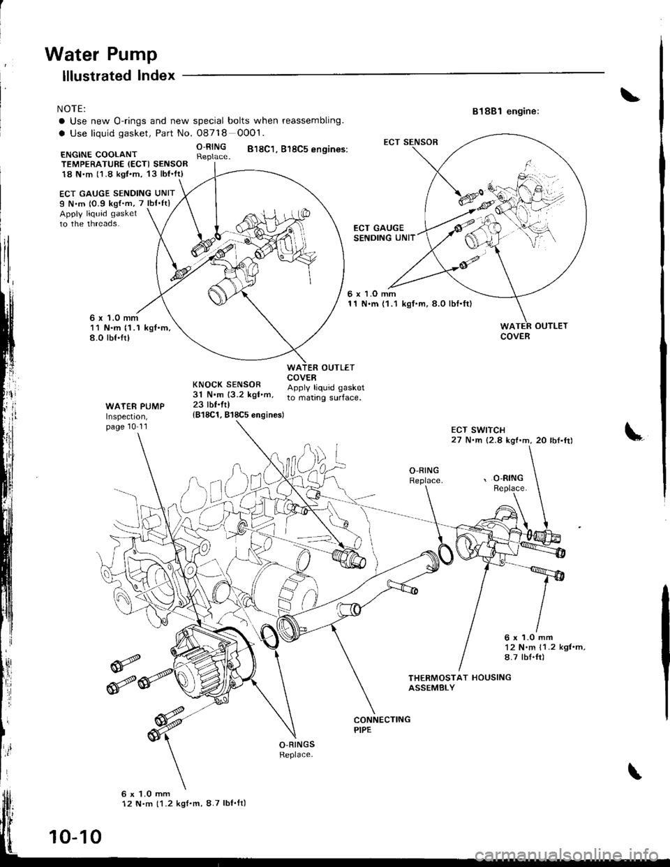
NOTE:
a Use new O-rings and new spgcial bolts when reassembling.
a Use liquid gasket, Part No. O8718 0001.
R;lll$ 818c1. 818c5 ensines:
ECT GAUGE SENDING UNITI N.m 10.9 kg{'m, 7 lbf'ftlApply liquid gasket
to the threads.
lllustrated lndex
6 x 1.0 mm11 N.m (1 .1 kgt.m.8.0 rbf.frt
ECT GAUGESENDING UNIT
818B1 engine:
OUTLET
ECT SWITCH27 N.m {2.8 kgf.m,20 lbf.fr)
ECT SENSOR
ENGINE COOLANTTEMPERATT,IRE IECTI SENSOR18 N'm (1.8 kgt.m, 13lbl'ft)
6 x 1.O mm11 N.m {1.1 kgI.m, 8.0 lbf.ft}
OUTLETCOVER
WATER PUMPInspecl|on,page 10-11
KNOCK SENSOR ADotv trouid oasket31 N.m 13.2 kgt.m, to ."t,nq .uif""".23 lbl.ftl
{818C1. 818C5 engines)
\,
O,RINGReplace.',O-RINGReplace.
6x1.0mm'12 N.m 11.2 kgt.m,8.7 lbI.fr)
THERMOSTAT HOUSINGASSEMBLY
O-RINGSReplace.
6 x 1.0 mm12 N.m (1.2 kgf.m, 8.7 lbI'ft)
COVER
10-10
Page 204 of 1680
Inspection
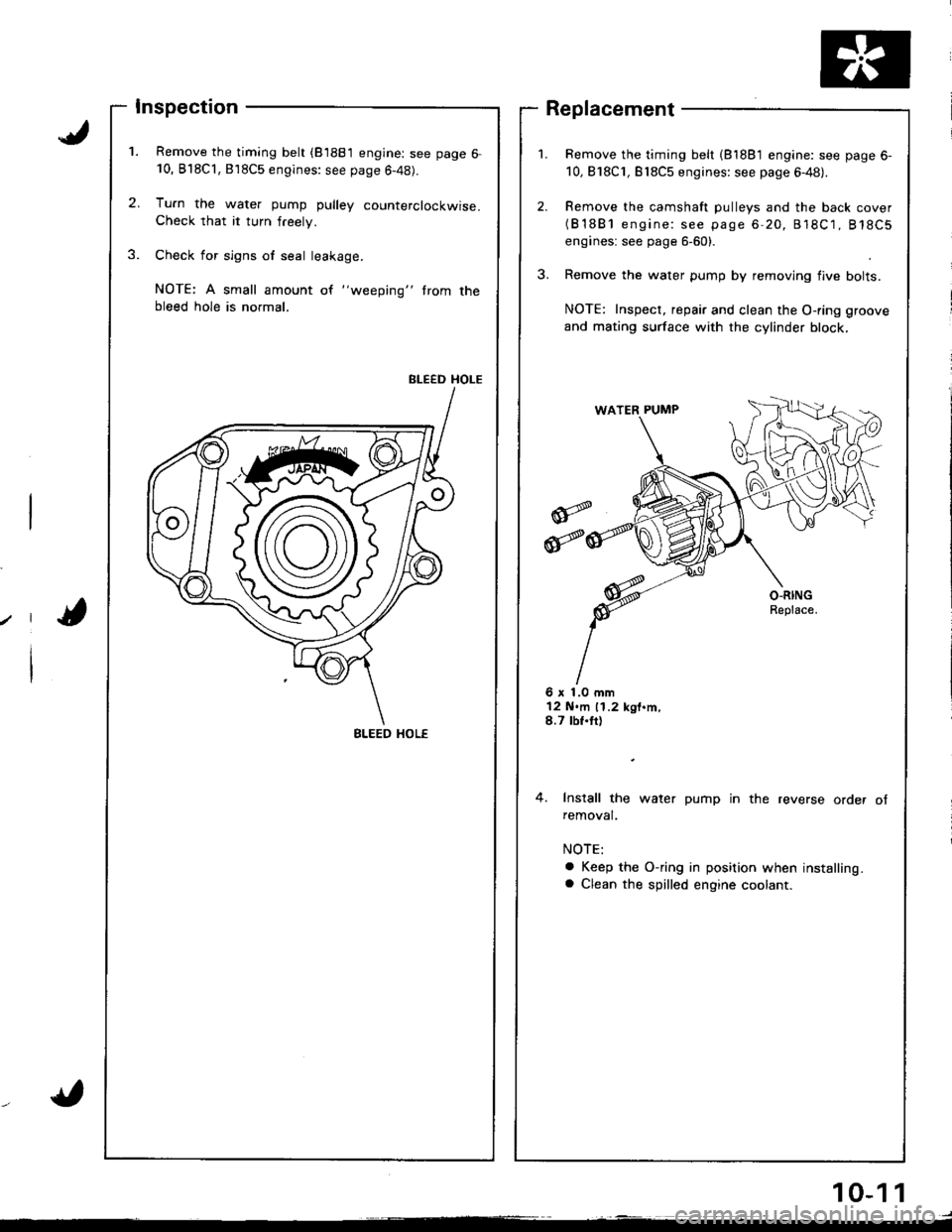
Remove the timing belt (81881 engine: see page 6-10, B'l8Cl,818C5 engines: see page 6-48).
Tu.n the water pump pulley counterclockwise.Check that it turn freely.
Check for sign6 of seal leakage.
NOTE: A small amount of "weeping" trom thebleed hole is normal.
BLEED HOLE
Remove the timing belt (81881 engine: see page 6-
10,818C1, Bl8C5 engines: see page 6-48).
Remove the camshaft pulleys and the back cover(B'1881 engine: see page 6-20, 818C1, 818C5
engines: see page 6-60).
Remove the water pump by removing flve bolts.
NOTE: Inspect, repair and clean the O-ring groove
and mating surface with the cylinder block,
Replacement
6 x 1.0 mm12 N.m 11.2 kgt.m,8.7 tbf.tt)
4. Install the water pump in the reverse order ofremoval.
a Keep the O-ring in position when installing.a Clean the spilled engine coolant.
BLEED HOL€
10-1 1
Page 758 of 1680
Bleeding
CAUTION:
. Oo not reuse the drsined fluid,
. Always use Genuine Honda DOT 3 Brake Fluid. Using
a non-Honda brake fluid can cause corrosion and
decrease the lile of the system,
a Make sure no dirt or other foreign matt€t is allowed
to contaminate the brske fluid.
. Do not spill brake fluid on tho car, it may damage the
pain; if brake fluid does contact the paint, wash it off
immediately with water.
NOTE: The reservoir on the master cylinder must be at
the MAX (upper) level mark at the start of bleeding pro-
cedure, and checked after bleeding each brake caliper.
Add fluid as required.
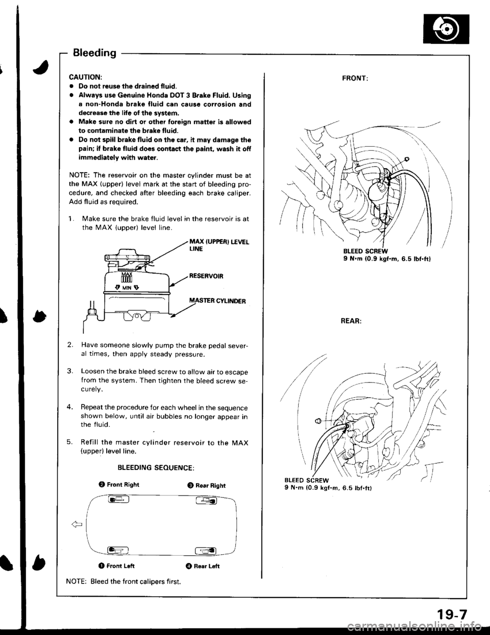
1. Make sure the brake fluid level in the reservoir is at
the MAX (upper) level line.
MAX (UPPER) I.IVELLINE
CYIINDER
Have someone slowly pump the brake pedal sever-al times, then apply steady pressure.
Loosen the brake bleed screw to allow air to escapefrom the system. Then tighten the bleed screw se-curely.
Repeat the procedure for each wheel in the sequenceshown below, until atr bubbles no longer appear inthe fluid.
Refill the master cylinder reservoir to the MAX(upperl level line,
BLEEDING SEOUENCE:
e, Front RightO Roa. Right
O Front Left Gt Raar L€ft
Bleed the front calipers first.NOTE:
19-7
FRONT:
REAR:
9 N.m {0.9 kgI'm,6.5 lbt.fr)
/
lc
,,
l,
Page 812 of 1680
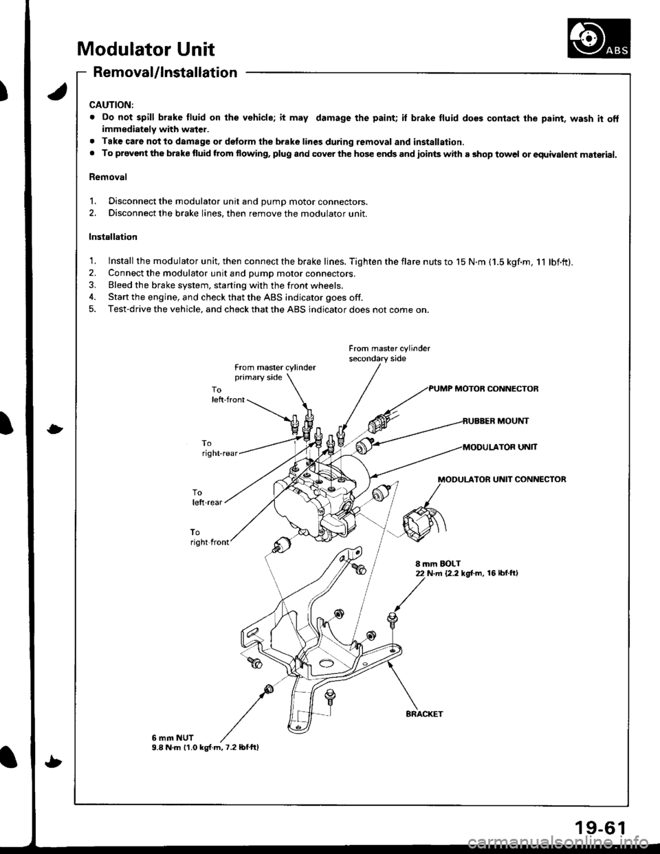
Modulator Unit
Removal/lnstallation
CAUTION:
. Do not spill brake fluid on lhe vehicle; it may damage the paint; il brake fluid does contact the paint, wash it offimmediately with water.
. Tak€ care notto damage or delorm the brake lines during removal and installation.. To provont the brake fluid ftom flowing, plug and cover the hos€ ends and ioints with a shop towel or equiyalent material.
Removal
1. Disconnect the modulator unit and DUmD motor connectors.
2. Disconnect the brake lines, then remove the modulator unit.
Installation
1. lnstall the modulator unit, then connect the brake lines. Tighten the flare nuts to 15 N.m (1.5 kgf.m, 11 lbf.ft).2. Connect the modulator unit and pump motor connectors.
3. Bleed the brake system, starting with the front wheels.
4. Start the engine, and check that the ABS indicator goes off.
5. Test-drive the vehicle, and check that the ABS indicator does not come on.
From master cylinder
from master cylinderprimary side
PUMP MOTOB CONNECTOR
MOUNT
UNlT
MODULATOR UNIT CONNECTOR
toright front
8 mm EOLT22 N.m {2.2 kg[.m, 16 lbl.ftl
6 mm NUT9.8 N.m 11.0 ks{.m,7.2lbtftl
9-6
Page 1656 of 1680

{b
Design Specifications
x1: At 6,000 engine rpm*2: At 7,600 engine rpm
0
(cont'd)
{
ITEMMETRICENGLISHNOTES
DIMENSIONSOverall Length 3-door4-doorOverall WidthOverall Height 3-door4-doorWheelbase 3-door4-doorTrack F/R
Ground Clearance
Seating Capacity
4,380 mm4,525 mm1,710 mm1,335 mm ]1,370 mm ]2,57O mm2,62O mm 11 ,415/1,470 mm I1,480/1,470 mm I1s0 mm I140 mm IFour (3-door),
172.4 in178.1 in67.3 in52.6 in53.9 in101.2 in103.1 in58.1/57.9 in58.3/57.9 in5.9 in5.5 tnFive (4-door)
Except Type RType RExcept Type RType R
weisht (usA)Gross Vehicle Weight Rating (GVWR)3.680 rbs
Weight (CANADA)Gross Vehicle Weight Rating (GVWR)1,670 kg
ENGINEType
Cylinder ArrangementBore and Stroke
Displacement
Compression Ratio
Valve Train
Lubrication SystemOil Pump Displacement
Water Pump Displacemenl
Fuel Required
8188l engine
818C1, Bl8C5 engines
81881 engine818C1, 818C5 engines81881 engine818C1, B18C5 engines81881 engine818C1 engine818C5 engineB1881 engine818C1, B18C5 engines
81881 engine818C1, B18CS enginesB1881 engine818C1, 818C5 enginesB1881 engine
818C1,818C5 engines
Water-cooled. 4-stroke DOHCgasoline engineWater-cooled, 4-stroke DOHCVTEC gasoline engineInline 4-cylinder, transverse81.0 x 89.0 mm | 3.19 x 3.50 in81.0 x 87.2 mm | 3.19 x 3.43 in1,834 cm3 (m/ ) | 112 cu-in1,797 cm3 (m/ ) | 110 cu-in9.210.010.6Belt driven, DOHC 4 valves per cylinderBelt driven, DOHC VTEC4 valves per cylinderForced and wet sump, trochoid pump50 f (53 US qt, 44 lmp qt)/minute*'71 ( (75 US qt,62 lmp qt)/minute*'� :
140 I 1148 US qt. 123 lmp qtl/minute*1140 t (148 US qt, 123 lmp qt)/minute*2UNLEADED gasoline with 86 PumpOctane Number or higherPremium UNLEADED gasoline with91 Pump Octane Number or higher
STARTERTypeNormal OutputNominal VoltageHour RatingDirection of RotationWeight MffAIT
Gear reductionMfi:1.2 kW, A,/T: 1.4 kW12V ,
30 secondsClockwise as viewed from gear end3.5 ks | 7.7 lbs3.7 kg | 8.2 lbs
CLUTCHClutch Type
Clutch Facing Area
M/TAfiM/T 81881, 818C1 engines818C5 engine
Single plate dry, diaphragm springTorque converter203 cm2 , 31 sq-in176 cm2 | 27 sq-in
TRANSMISSIONTransmission Type
Primary Reduction
M/TAITSynchronized S-speed forward, 1 reverseElectronical ly control led4-speed automatic, 1 reverseDirect 1 : 1
3-15