wheel bearing ACURA INTEGRA 1998 Service Repair Manual
[x] Cancel search | Manufacturer: ACURA, Model Year: 1998, Model line: INTEGRA, Model: ACURA INTEGRA 1998Pages: 1680, PDF Size: 53.14 MB
Page 146 of 1680
I
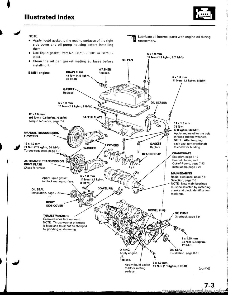
lllustrated Index
INOTE:
. Apply liqujd gasket to the mating surfaces ot the right
side cover and oil pump housing before installing
them.
. Use liquid gasket,
0003.
. Clea n the oil pan
installing it.
B18Bl engine:
Part No. 087'18 - 0001 or 08718 -
gasket mating surfaces before
Lubricate all internal parts with engine oil during
reassemDly.
6x1.0mm12 N.m {1.2 kg{.m,8.7 lbt.ft}
6x1.0mm11 N.m 11.1 kg'f.m,8 lbt.ftl
OIL SCREEN
DEAIN PLUG4il N.m 14.5 kgt m,33 tbtft)
BAFFLE PLATE
6x1.0mm1'l N.m (1.1 kgt.m,8 rbr.ftl
OIL PAN
O.FING
CAP
DOWEL PINS
WASHERReplace.
GASKETReplace.
6x1.0mm11 N.m (1.1 kgl.m, 8 lbl.ft)
12 x 1.0 mm103 Nm 110.5ks{.m,76lbf.ft}
MANUAL TRANSMISSIONFLYWHEEL
12 x 1.0 mm74 N.m 17.5 kgf.m,54lbf.tr)Torque sequence, page 7-7
AUTOMATIC TRANSMISSION
WASHERcovERsGASKETReplace.
11 x 1.5 mm76 N.m17.8 kgt m, 56 lbtft)Apply engine oilto the boltthreads and the washers.NOTE: After torquingeach cap, turn crankshaftto check for binding.
ORIVE PLATECheck for cracks.
Apply liquid gasketto block mating surface.
CRANKSHAFTEnd play, page 7-12Runout, Taper, andOut-of'Round, page 7-13Installation, page 7-26
MAIN AEARINGRadialclearance, page 7 8Selection, page 7'8NOTE: New main bearingsmust be selected by matchingcrank and block identificationmarkrngs.
I
i
OIL SEALlnstallation, page 7
RIGHTSIDE COVER
THRUST WASHERSGrooved sides face outward.NOTE: Thrust washer thicknessis fixed and must not be changedby grinding or shamming.
8 x 1.25 mm21 N..n l2.1kga'r,�,17 tbf.ft)
OIL SEALInstallation, page 8-1 1Apply engineorl.Replace.
Apply liquid gasket
to block matingsurface,
6x1.0mm11 N.m t1.lilh{.m,I lbf.ft}(cont'd)
Page 151 of 1680
/
li
l
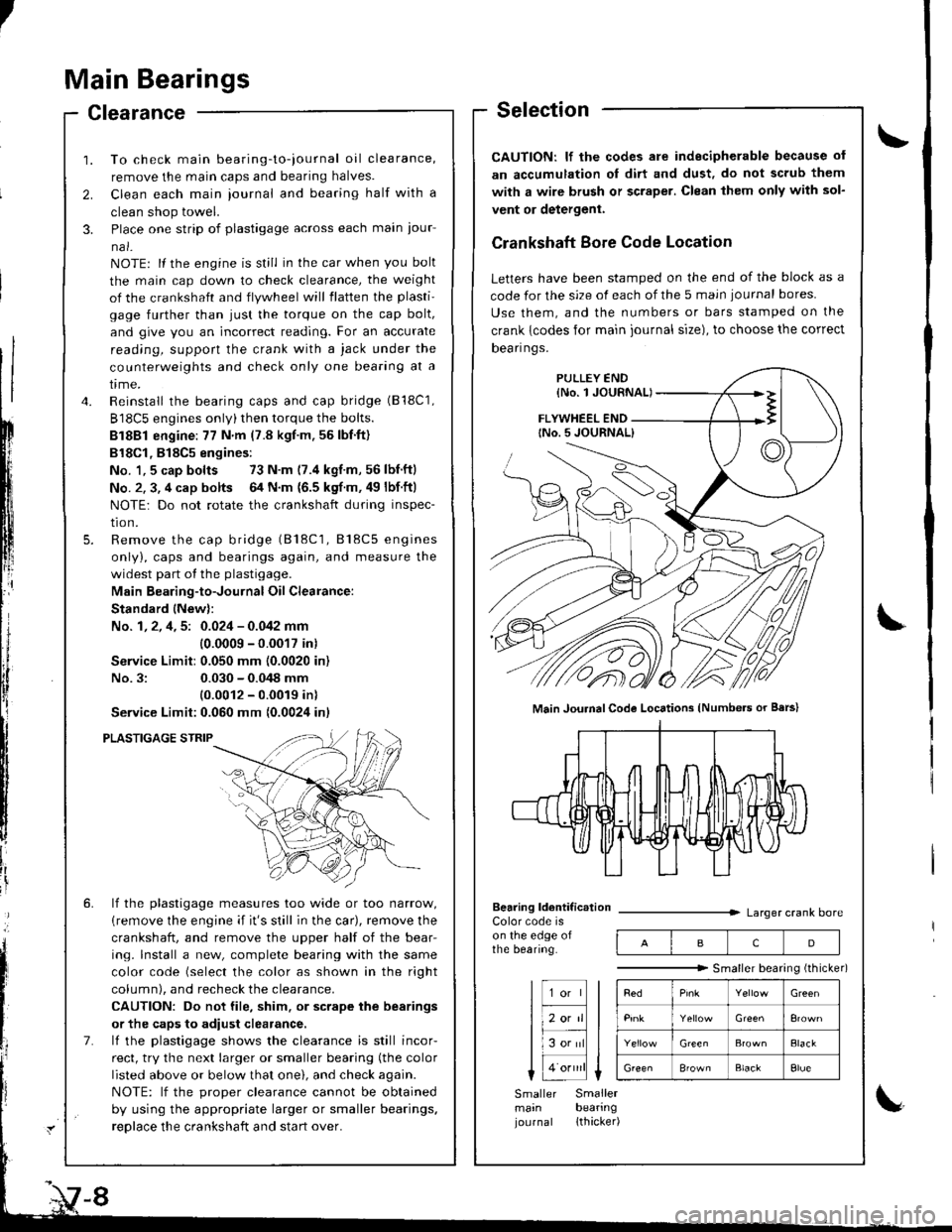
Main Bearings
Clearance
2.
3.
1.
4.
To check main bearing-to-iournal oil clearance,
remove the main caps and bearing halves.
Clean each main iournal and bearing half with a
clean shop towel.
Place one strip of plastigage across each main iour-
na l-
NOTE: lf the engine is still in the car when you bolt
the main cap down to check clearance, the weight
of the crankshaft and flywheel will flatten the plasti'
gage further than just the torque on the cap bolt,
and give you an incorrect reading. For an accurate
reading, support the crank with a jack under the
counterweights and check only one bearing at a
trme.
Reinstall the bearing caps and cap bridge (B18C1,
B18C5 engines only)then torque the bolts.
Bl8Bl engine: 77 N'm (7.8 kgt.m.56lbf.ft)
B18Cl,818C5 engines:
No. 1,5 cap bolts 73 N.m (7.4 kgf.m,56lbnftl
No. 2. 3, 4 cap bolts 64 N.m {6.5 kgf m. 49 lbf ftl
NOTE: Do not rotate the crankshaft during inspec-
tro n.
Remove the cap bridge (818C1, 818C5 engines
only), caps and bearings again, and measure the
widest part of the plastigage.
Main Bearing-to-Journal Oil Clearance:
Standard lNew):
No. 1, 2, 4, 5: 0.024 - 0.042 mm
10.0009 -0.0017 in)
Service Limit:0.050 mm (0.0020 in)
No.3:0.030 - 0.048 mm
10.0012 - 0.0019 inl
Service Limit:0.060 mm {0.0024 inl
PLASTIGAGE STRIP
lf the plastigage measures too wide or too narrow,
{remove the engine if it's still in the car), remove the
crankshaft, and remove the upper half of the bear-
ing. lnstall a new, complete bearing with the same
color code (select the color as shown in the right
column), and recheck the clearance.
CAUTION: Do not file, shim. or scrape the bearings
or the caps to adiust clearance.
lf the plastigage shows the clearance is still incor-
rect, try the next larger or smaller bearing (the color
listed above or below that one), and check again.
NOTE: lf the oroDer clearance cannot be obtained
by using the appropriate larger or smaller bearings.
reolace the crankshaft and start over.
Selection
CAUTION: lf the codes ale indecipherable because of
an accumulation oI dirt and dust, do not scrub them
with a wire bru6h or scraper. Clean lhem only with sol-
vent or detergent.
Crankshaft Bore Code Location
Letters have been stamped on the end of the block as a
code for the size of each of the 5 main iournal bores
Use them, and the numbers or bars stamped on the
crank {codes for main journal size), to choose the correct
Dean nqs,
FLYWHEEL END
Main JouhalCode Locations (Numbe.s or Bars)
Bearing ldentif ic.tionColor code ison the edge ofthe bearing.
Larger crank bore
acD
"""""""" Smallerbearingithicker)
Green
Elack
B'ownBlackElue
Smaller Smallermain bearingjournal lthacker)
Page 357 of 1680
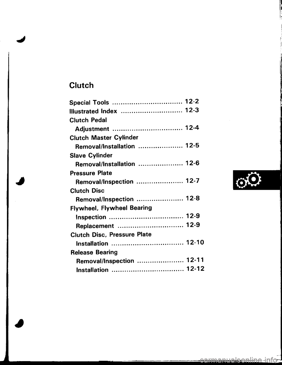
Clutch
Speciaf Tools ........ .'--"" 12-2
lflustrated Index ........ ".' 12-3
Clutch Pedal
Adjustment "..".""'...' 12-4
Clutch Master Cylinder
Removal/lnstallation -'.' 12-5
Slave Cylinder
Removal/lnstallation '..' 12-6
Pressure Plate
Removal/lnspection .'-.' 12-7
Clutch Disc
Removal/lnspection '...' 12-a
Flywheel, Flywheel Bearing
fnspection ' 12-9
Replacement .................'............. 1 2-9
Clutch Disc, Pressure Plate
lnstallation ................. 12-10
Release Bearing
Removal/lnspection "'.' 12-11
fnstaffation ".""".-'."'. 12-12
Page 359 of 1680
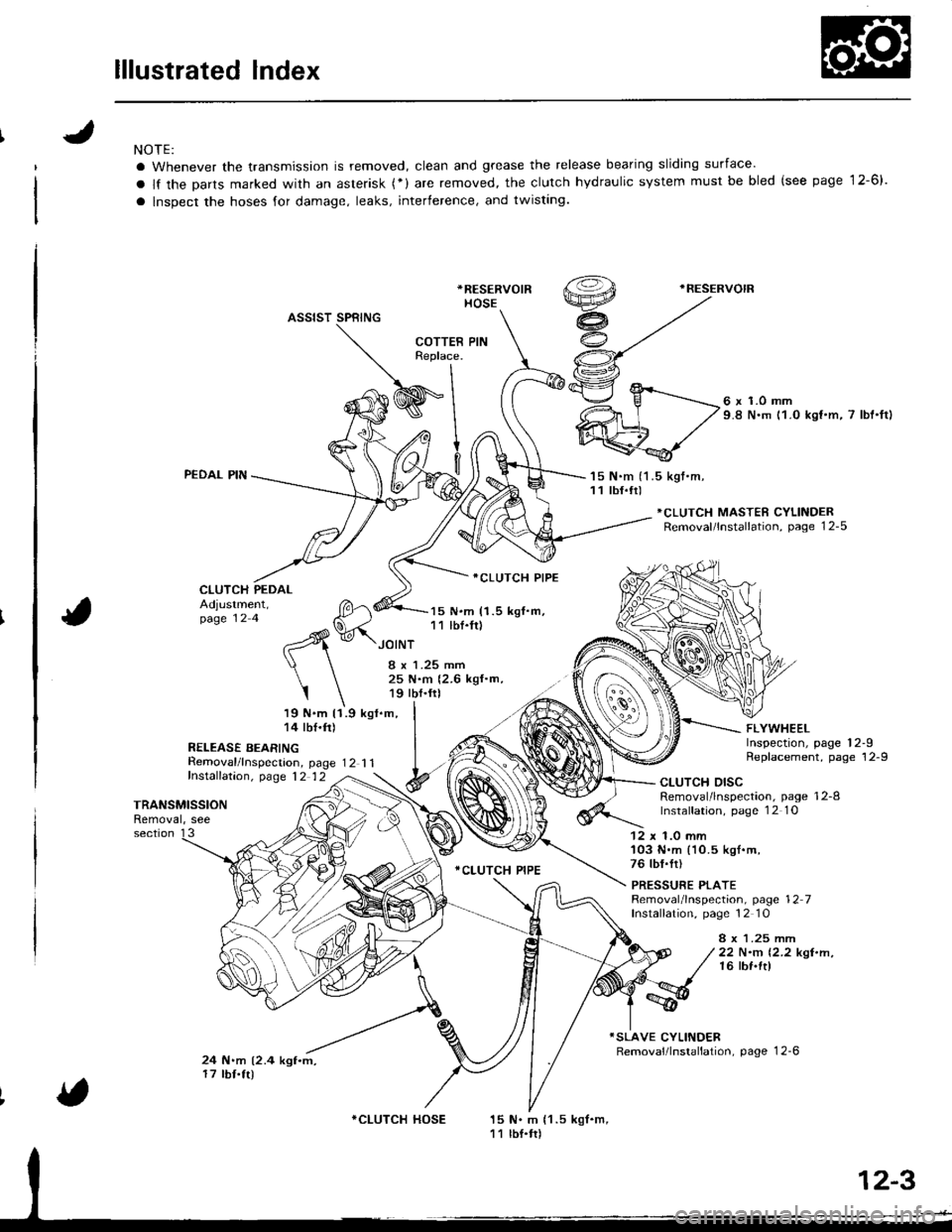
lllustrated Index
NOTE:
a Whenever the transmission is removed, clean and grease the release bearing sliding surface'
a lf the Darts marked with an asterisk (*) are removed, the clutch hydraulic system must be bled (see page 12-6).
a lnspect the hoses for damage, leaks, interference, and twisting.
*RESERVOIR
HOSE
.RESERVOIR
ASSIST SPRING
PEDAL PIN
CLUTCH PEDAL
Removal/lnspecrion, page 12 1 1fnstalfation, p,age 12 12
6 x 1.0 mm9.8 N.m 11.0 kst.m, 7 lbt'ftl
'15 N.m (1 .5 kgt.m,11 tbf.tr)
*CLUTCH MASTER CYLINDERRemoval/lnstallation, page 12-5
Adjustment,page 12 4
19 N.m 11.9 kgl.m,14 tbf.ft)
R€LEASE BEARING
15 N.m (1.5 kgf.m,11 lbf.fr)
ICLUTCH PIPE
.CLUTCH PIPE
FLYWHEELInspection, page 12-9Replacement, page 12-9
JOINT
I x 1.25 mm25 N.m {2.6 kgf.m,19 tbf.frl
I
TRANSMISSIONRemoval, see
CLUTCH DISCRemoval/lnspection, page 12-8lnstalfation, page 1 2 1O
section 1312 x 1.0 mm'103 N.m (10.5 kgl.m,76 tbf.fr)
PRESSURE PLATERemoval/lnspection, page 12 7Installation, page 12 10
8 x 1.25 mrr|22 N.m 12.2 kgt.n,16 lbf.ft)
24 N.m (2.4 kgf.m,17 tbf.tr)
15 N. m {1 .5 kgf.m,11 lbf.tr)
COTTERReplace.
I
WInl
9l
v.^- fl
*CLUTCH HOSE
Page 365 of 1680

Flywheel, Flywheel Bearing
Inspection
t
',4
i
Replacement
1. Install the special tool.
MOUNTING BOLTS
Remove the flywheel mounting bolts in a crisscrosspattern in several steps as shown, then.emove the
Jlvwheel.
Bemove the flywheel bearing from the flywheel.
(cont'd)
FLYWHEEL
I
1.Inspect the ring gear teeth tor wear and damage.
Inspect the clutch disc mating surtace on the
flywheel for wear, cracks, and burning.
l\,reasure the flywheel runout using a dial indicator
through at least two full turns. Push agsinst the
Jlywheel each time you turn it to take up the crank-
shatt thrust washer clearance.
NOTE: The runout can ba measured with engine in-
stalled.
SiEndrrd (Ncw): 0.05 mm (0.002 inl max.
SerYicc Llmh: 0.15 mm (0.006 inl
DIAL INOICATOR
lf the runout is more than the service limit, reolace
the flywheel.
Turn the inner race of the flywheel bearing with your
tinger. The bearing should turn smoothly and quiet-
ly. Check that the bearing outer race tits tightly in
the flvwheel.
FLYWHEELBEARING
lf the race does not turn smoothly, quietly, or tit
tight in the flywheel, replace the flywheel bearing.
4.
FLYWHEEL
12-9
Page 366 of 1680

Clutch Disc,
Flywheel, Flywheel BearingPressure Plate
Replacement (cont'd)Installation
1. Install the ring gear holder.
CLUTCH DISC
1tti
CLUTCH ALIGNMENT SHAFT07NAF-PR30100HANDLE07936 -3710100
Apply grease to the spline ot the clutch disc, then
install the clutch disc using the special tools as
shown.
NOTE: Use only Super High Temp Urea Grease (P/N
o8798 9002).
3. Insrall the pressure Plate.
CLUTCH ALIGNMENT SHAFT07NAF-PR30100HANDLE07936-3710100
RING GEAR HOI-DER07LAB - PV001O0 or07924-PD20003
4. Drive the new flywheel bearing into the flywheel us-
ing the special tools as shown.
DRIVER07749 -0010000
FLYWHEEL
Align the hole in the llywheel with the crankshalt
dowel pin and installthe flywheel. Installthe mount-
ing bolts fingertight.
Install the special tool as shown, then torque the
flvwheel mounting bolts in a crisscross pattern in
several steps as shown-
6.
ATTACHMENT,32x35mm07746 0010100
5.
RING GEAE HOLDER07LAB-Pv00100 or07924-PD20003MOUNTING BOLTS12 x 1.0 mm103 N.m (10.5 kgf .m,
76 tbt.frl
FLYWHEEL BEARING
FLYWHEEL
6!-o
&#,oit
12-10
PRESSURE PLATE
Page 509 of 1680
NOTES
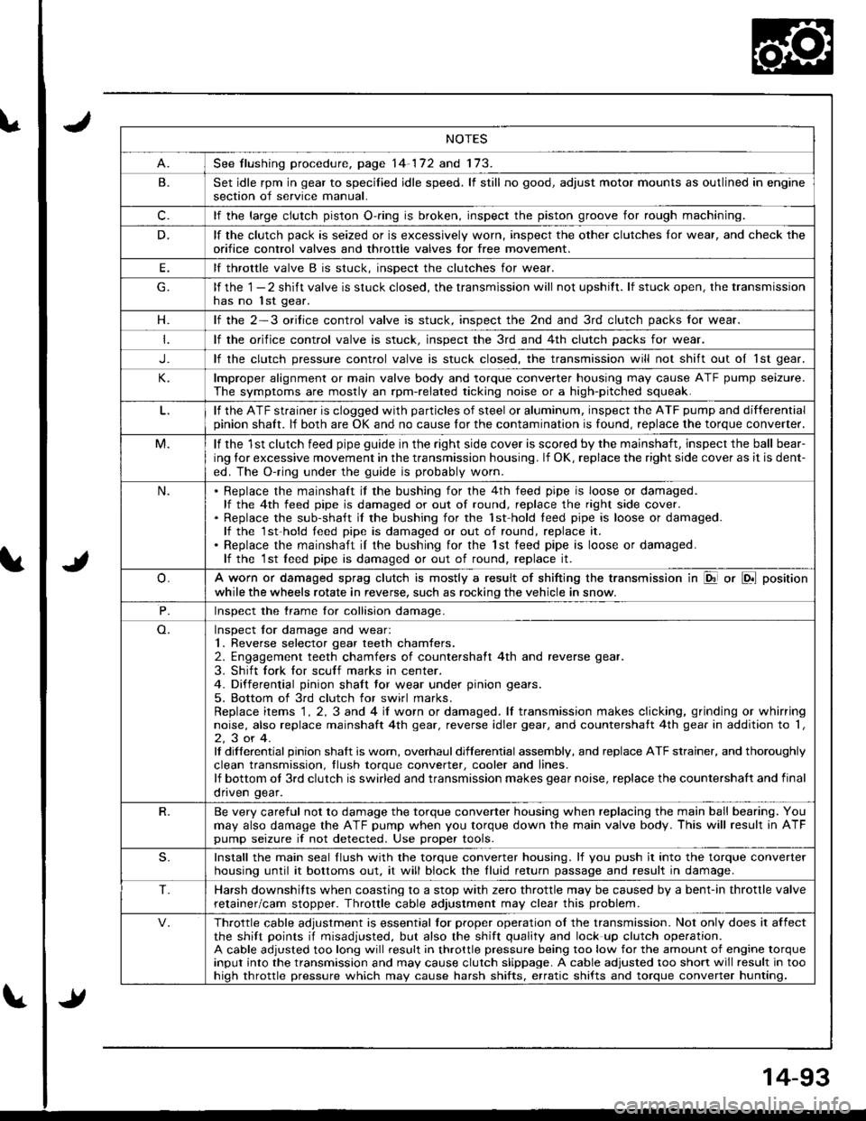
See flushing procedure, page 14-172 and 173.
B.Set idle rpm in gear to specilied idle speed. lf still no good, adjust motor mounts as outlined in enginesection of service manual.
c.lf the large clutch piston O-.ing is broken, inspect the piston groove for rough machining.
D.lf the clutch pack is seized or is excessively worn, inspect the other clutches lor wear, and check the
orifice control valves and throttle valves for free mov€ment.
E.lf throttle valve B is stuck. insDect the clutches for wear.
lf the 1 - 2 shift valve is stuck closed, the transmission will not upshitt. lf stuck open, the transmissionhas no lst gear.
H.lf the 2-3 orilice control valve is stuck, inspect the 2nd and 3rd clutch packs for wear.
lf the orifice control valve is stuck. inspect the 3rd and 4th clutch packs for wear.
J.lf the clutch pressure control valve is stuck closed, the transmission will not shift out oI 1st gear.
lmproper alignment or main valve body and torque converter housing may cause ATF pump seizure.
The symptoms are mostly an rpm-related ticking noise or a high-pitched squeak.
lf the ATF strainer is clogged with particles of steel or aluminum, inspect the ATF pump and differentialpinion shaft. lf both are OK and no cause for the contamination is found, replace the torque converter.
M.lf the 1st clutch feed pipe guide in the right side cover is scored by the mainshaft, inspect the ball bear-
ing lor excessive movement in the transmission housing. lf OK, replace the right side cover as it is dent-
ed. The O-ring under the guide is probably worn.
N.Replace the mainshaft if the bushing for the 4th feed pipe is loose or damaged.lf the 4th feed pipe is damaged or out of round, replace the right side cover.Replace the sub-shaft il the bushing for the 1st-hold teed pipe is loose or damaged.lf the 1st-hold teed pipe is damaged or out of round, replace it.
Replace the mainshaft iI the bushing for the lst feed pipe is loose or damaged.lf the 1st leed pipe is damaged or out of round, replace it.
A worn or damaged sprag clutch is mostly a result of shifting the transmission in El or LDll position
while the wheels rotate in reverse, such as rocking the vehicle in snow.
P.Inspect the trame for collision damage.
Inspect lor damage and wear:1. Reverse selector gear teeth chamfers.2. Engagement teeth chamfers of countershaft 4th and reverse gear.
3. Shift fork for scuff marks in center.4. Differential pinion shaft tor wear under pinion gears.
5. Bottom of 3rd clutch for swirl marks.Replace items 1 . 2, 3 and 4 iI worn or damaged. lf transmission makes clicking, grinding or whirringnoise, also replace mainshaft 4th gear, reverse idler gear, and countershatt 4th gear in addition to '1,
2,3or4.It differential pinion shalt is worn, overhaul differential assembly, and replace ATF strainer, and thoroughly
clean transmission, tlush torque conveder, cooler and lines.lf bottom ot 3rd clutch is swirled and transmission makes gear noise, replace the countershaft and final
onven qear.
R.Be very careful not to damage the torque converter housing when replacing the main ball bearing. You
may also damage the ATF pump when you torque down the main valve body. This will result in ATFpump seizure if not detected. Use proper tools.
S.Install the main seal llush with the torque converter housing. lf you push it into the torque converterhousing until it bottoms out. it will block the fluid return passage and result in damage.
T.Harsh downshifts when coasting to a stop with zero throttle may be caused by a bent-in throttle valve
retainer/cam stopper. Throttle cable adjustment may clear this problem.
Throttle cable adjustment is essential tor proper operation ol the transmission. Not only does it affectthe shift points if misadjusted, but also the shift quality and lock up clutch operation.A cable adjusted too long will result in throttle pressure being too low for the amount of engine torqueinput into the transmission and may cause clutch slippage. A cable adjusted too short will result in toohiqh throttle pressure which may cause harsh shifts, erratic shifts and torque converter hunting.
Page 710 of 1680
Suspension
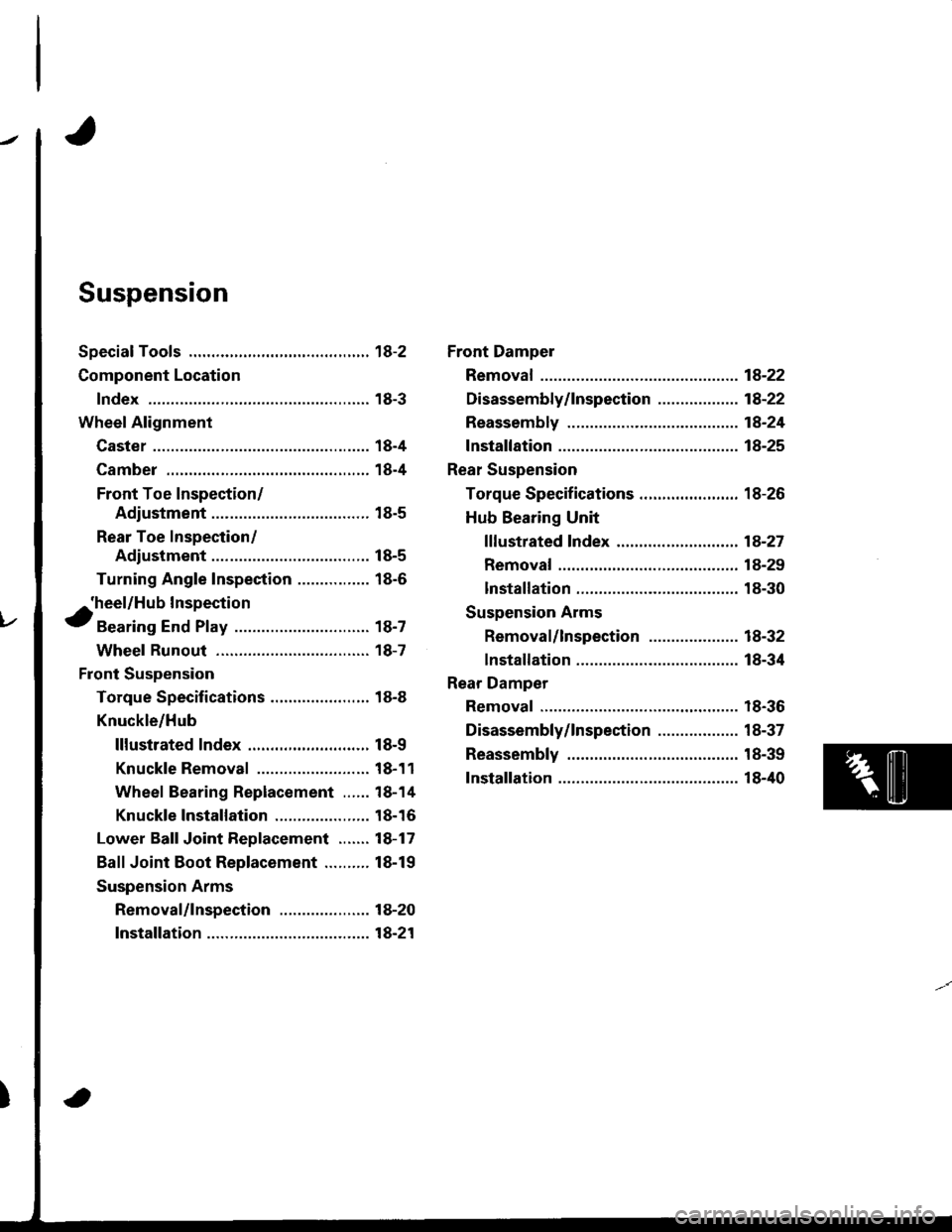
Special Tools ............. 18-2
Component Location
lndex ................ ...... 18-3
Wheel Alignment
Caster ............... ...... 18-4
Camber .................. 18-4
Front Toe Inspection/
Adjustment ........ 18-5
Rear Toe Inspection/
Adiustment ........ 18-5
Turning Angle Inspection ................ 18-6
^'heel/Hub Inspection
tBearing End Play .............................. 18-7
Wheel Runout ....... 18-7
Front Suspension
Torque Specifications ...................... 18-8
Knuckle/Hub
lllustrated lndex .........,................. 18-9
Knuckle Removal ......................... 18-11
Wheel Bearing Replacement ...... 18-14
Knuckle 1nsta11ation ..................... 18-16
Lower Ball Joint Replacement ....... 18-17
Ball Joint Boot Replacement .......... 18-19
Suspension Arms
Removal/lnspection .................... 18-20
lnstallation ......... 18-21
Front Dampel
Removal ................. 18-22
Disassembly/lnspection ............. ..... 18-22
Reassembly ........... 18-24
fnstaffation ............. 1A-25
Rear Suspension
Torque Specifications ...................... 18-26
Hub Bearing Unit
f f f ustrated lndex ................ ........... 18-27
Removal ............. 18-29
lnstallation ......... 18-30
Suspension Arms
Removal/lnspection .................... 18-32
lnstallation ......... 18-34
Rear Damper
Removal ................. 18-36
Disassembly/lnspection .................. 18-37
Reassembly ........... 18-39
Installation ............. 18-40
Page 712 of 1680
Component Location
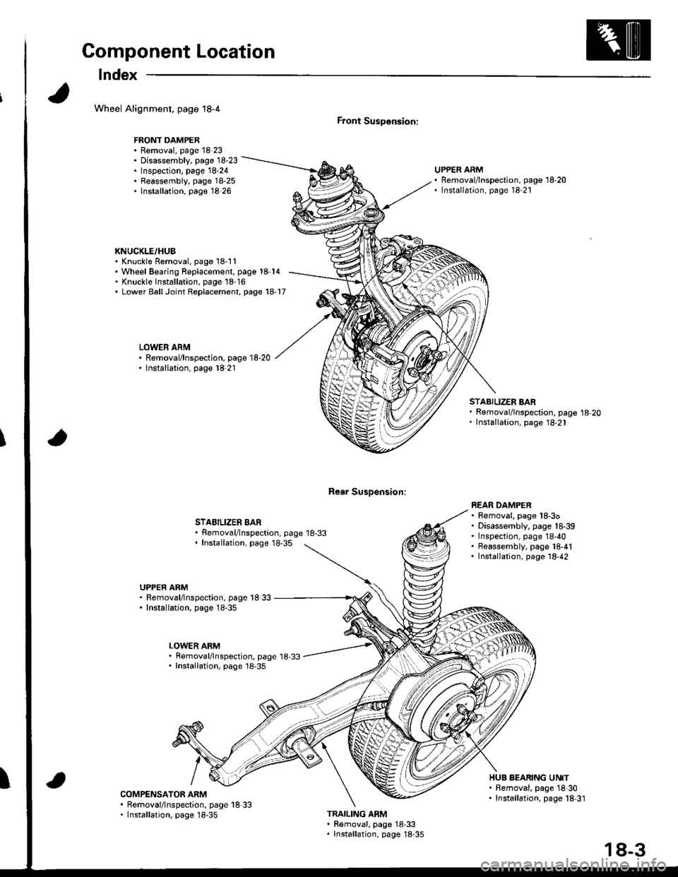
lndex
Wheel Alignment, page 18-4
FRONT DAMPER. Removal, page 18 23' Disassembly, page 18-23. Inspection, page 18-24. Reassembly, page 18-25. lnstallation. page 18 26
KNUCKLE/HUB. Knuckle Removal, page 18-11'Wheel Bearing Replacement, page 18-14' Knuckle lnst6llation, page 18-16. Lower BallJoint Replacement, page 18-17
LOWER ARM. Removal/lnspection, page 18-20. lnstallation, page l8 21
Front SusDonsion:
Rear Susoension:
UPPER ARMRemoval/lnspection, page 18-20Installation, page 18-21
STABILIZER BARRemoval/lnspectaon, page 18-33Installation, page 18-35
STABILIZER BARRemoval/lnspection, page 18-20Installation, page 18,21
REAR DAMPER. Removal, page 18-3o. Disassembly, page 18-39' Inspection, page 18-40. Reassembly, page l8-41. Installation, page 18,42
UPPER ARM. Removal/lnspection, page l8 33. Installation, page 18-35
LOWER ARM. Removal/lnspection, page 18,33. lnstallation, page 18-35
ICOMPENSATOR ARM. Removal/lnspection, page 18 33. Installation, page 18-35
HUB BEARING UNIT. Bemoval, page 18'30. Installation, page 18,31
TRAILING ARM. Removal, page 18-33. lnstallation, page 18-35
18-3
Page 716 of 1680
Wheel/Hub Inspection
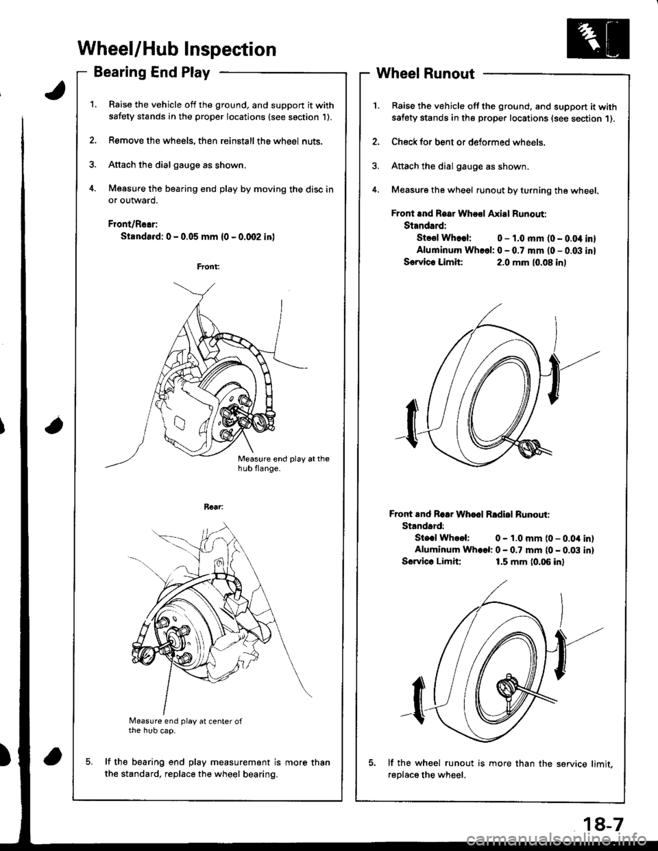
Bearing End Play
Raise the vehicle off the ground, and support it with
safety stands in the proper locations (see saction 1).
Remove the wheels, then reinstallthe whe6l nuts.
Attach the dial gauge as shown.
Measure the bearing end play by moving the disc in
or outward.
Front/Rear:
Standa.d: 0 - 0.05 mm (0 - 0.qr2 in)
a
Measure end play at center ofthe hub cap.
lf the bearing end play measurement is
the standard, replace the wheel bearing.
Wheel Runout
Raise the vehicle off the ground, and support it withsatety stands in the proper locations (see section 1).
Check for bent or deformed wheels.
Attach the dial gauge as shown.
Measure the wheel runout by turning the wheel.
Front and Roar Whool Axial Runout:
Standard:
Stcsl Whoel: 0 - 1.0 mm (0 - 0.04 inl
Aluminum Whcel: 0 - 0.7 mm (0 - 0.03 inl
Sorvlc. Limit:2.0 mm (0.08 inl
Front End Roar Whod Rldisl Runouti
Standard:
Ste.l Whool: 0 - 1.0 mm (0 - 0.04 inlAluminum Wh.el: 0 - 0.7 mm (0 - 0.03 inl
Sorvico Limit:1.5 mm (0.06 inl
lf the wh€el runout is more than the service limit,
reDlace the wheel.
more than
18-7