glove box ACURA NSX 1991 Service Repair Manual
[x] Cancel search | Manufacturer: ACURA, Model Year: 1991, Model line: NSX, Model: ACURA NSX 1991Pages: 1640, PDF Size: 60.48 MB
Page 39 of 1640
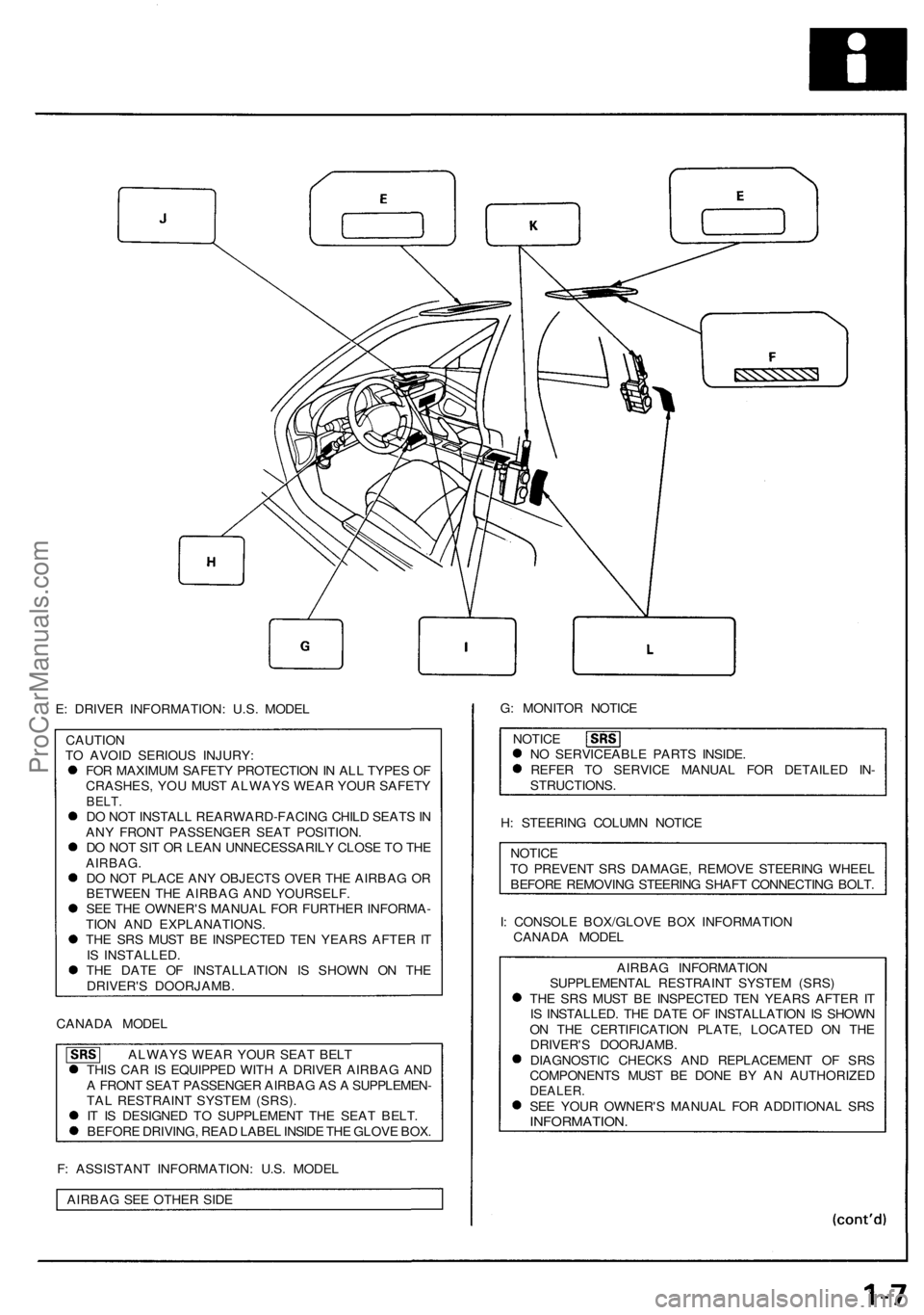
E: DRIVER INFORMATION: U.S. MODEL
CAUTION
TO AVOID SERIOUS INJURY:
FOR MAXIMUM SAFETY PROTECTION IN ALL TYPES OF
CRASHES, YOU MUST ALWAYS WEAR YOUR SAFETY
BELT.
DO NOT INSTALL REARWARD-FACING CHILD SEATS IN
ANY FRONT PASSENGER SEAT POSITION.
DO NOT SIT OR LEAN UNNECESSARILY CLOSE TO THE
AIRBAG.
DO NOT PLACE ANY OBJECTS OVER THE AIRBAG OR
BETWEEN THE AIRBAG AND YOURSELF.
SEE THE OWNER'S MANUAL FOR FURTHER INFORMA-
TION AND EXPLANATIONS.
THE SRS MUST BE INSPECTED TEN YEARS AFTER IT
IS INSTALLED.
THE DATE OF INSTALLATION IS SHOWN ON THE
DRIVER'S DOORJAMB.
CANADA MODEL
ALWAYS WEAR YOUR SEAT BELT
THIS CAR IS EQUIPPED WITH A DRIVER AIRBAG AND
A FRONT SEAT PASSENGER AIRBAG AS A SUPPLEMEN-
TAL RESTRAINT SYSTEM (SRS).
IT IS DESIGNED TO SUPPLEMENT THE SEAT BELT.
BEFORE DRIVING, READ LABEL INSIDE THE GLOVE BOX.
F: ASSISTANT INFORMATION: U.S. MODEL
AIRBAG SEE OTHER SIDE
G: MONITOR NOTICE
NOTICE
NO SERVICEABLE PARTS INSIDE.
REFER TO SERVICE MANUAL FOR DETAILED IN-
STRUCTIONS.
H: STEERING COLUMN NOTICE
NOTICE
TO PREVENT SRS DAMAGE, REMOVE STEERING WHEEL
BEFORE REMOVING STEERING SHAFT CONNECTING BOLT.
I: CONSOLE BOX/GLOVE BOX INFORMATION
CANADA MODEL
AIRBAG INFORMATION
SUPPLEMENTAL RESTRAINT SYSTEM (SRS)
THE SRS MUST BE INSPECTED TEN YEARS AFTER IT
IS INSTALLED. THE DATE OF INSTALLATION IS SHOWN
ON THE CERTIFICATION PLATE, LOCATED ON THE
DRIVER'S DOORJAMB.
DIAGNOSTIC CHECKS AND REPLACEMENT OF SRS
COMPONENTS MUST BE DONE BY AN AUTHORIZED
DEALER.
SEE YOUR OWNER'S MANUAL FOR ADDITIONAL SRS
INFORMATION.ProCarManuals.com
Page 531 of 1640
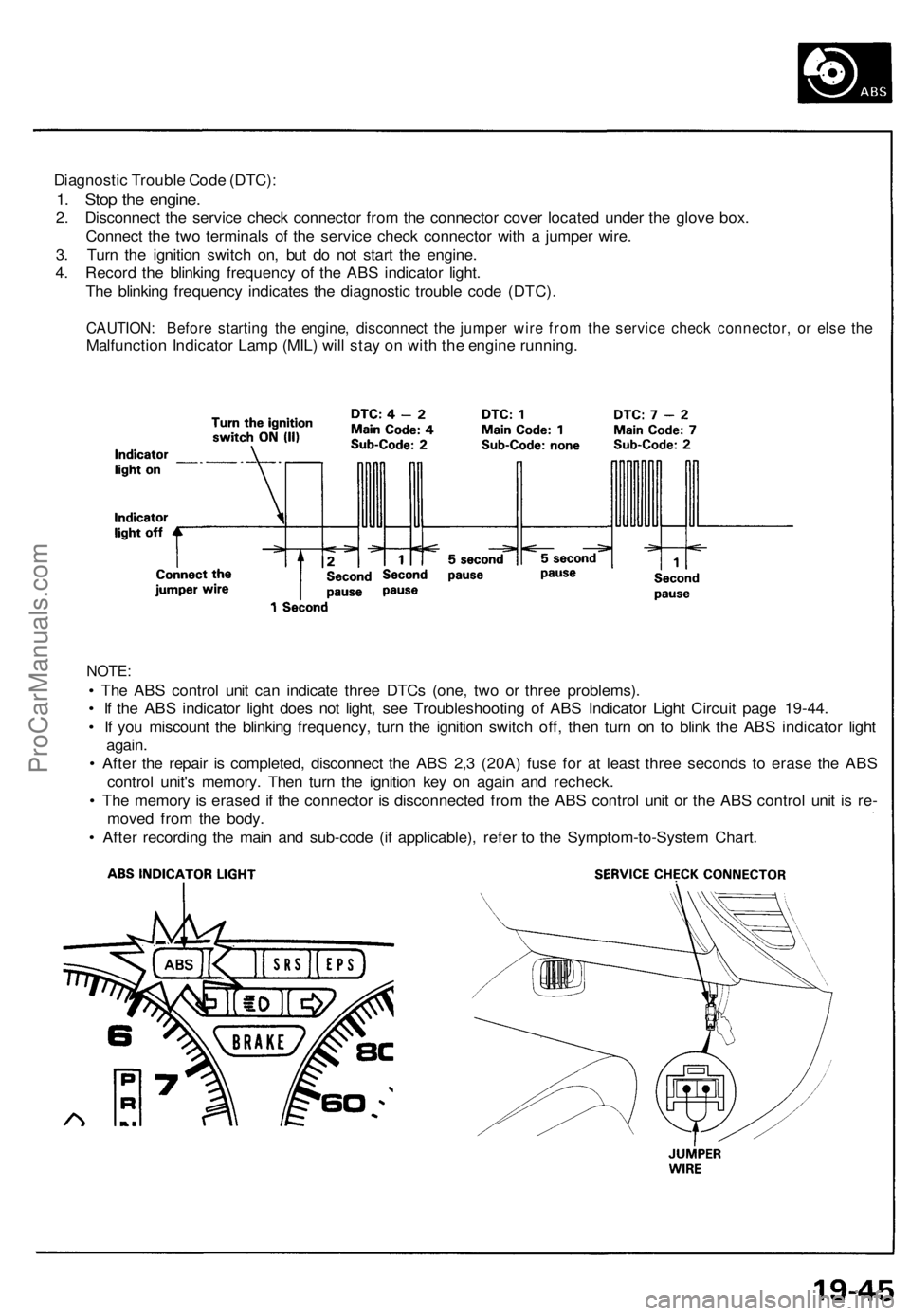
Diagnostic Trouble Code (DTC):
1. Stop the engine.
2. Disconnect the service check connector from the connector cover located under the glove box.
Connect the two terminals of the service check connector with a jumper wire.
3. Turn the ignition switch on, but do not start the engine.
4. Record the blinking frequency of the ABS indicator light.
The blinking frequency indicates the diagnostic trouble code (DTC).
CAUTION: Before starting the engine, disconnect the jumper wire from the service check connector, or else the
Malfunction Indicator Lamp (MIL) will stay on with the engine running.
NOTE:
• The ABS control unit can indicate three DTCs (one, two or three problems).
• If the ABS indicator light does not light, see Troubleshooting of ABS Indicator Light Circuit page 19-44.
• If you miscount the blinking frequency, turn the ignition switch off, then turn on to blink the ABS indicator light
again.
• After the repair is completed, disconnect the ABS 2,3 (20A) fuse for at least three seconds to erase the ABS
control unit's memory. Then turn the ignition key on again and recheck.
• The memory is erased if the connector is disconnected from the ABS control unit or the ABS control unit is re-
moved from the body.
• After recording the main and sub-code (if applicable), refer to the Symptom-to-System Chart.ProCarManuals.com
Page 542 of 1640
ABS Contro l Uni t
Replacemen t
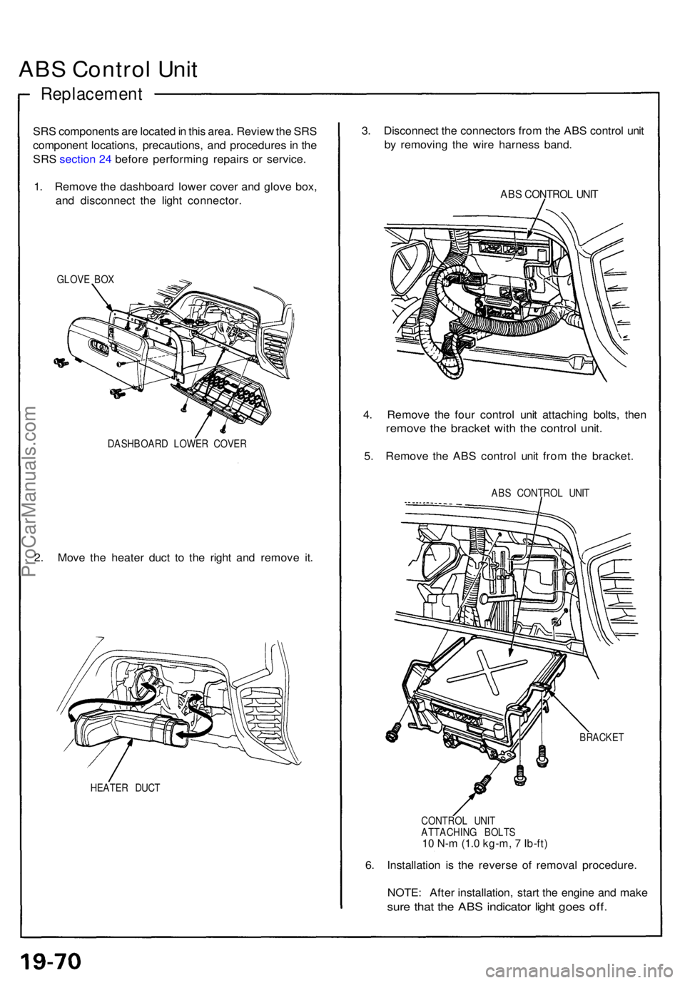
SRS component s ar e locate d in thi s area . Revie w th e SR S
componen t locations , precautions , an d procedure s in th e
SR S
sectio n 2 4 befor e performin g repair s o r service .
1 . Remov e th e dashboar d lowe r cove r an d glov e box ,
an d disconnec t th e ligh t connector .
GLOVE BO X
DASHBOAR D LOWE R COVE R
2. Mov e th e heate r duc t t o th e righ t an d remov e it .
HEATE R DUC T
3. Disconnec t th e connector s fro m th e AB S contro l uni t
b y removin g th e wir e harnes s band .
ABS CONTRO L UNI T
4. Remov e th e fou r contro l uni t attachin g bolts , the n
remov e th e bracke t wit h th e contro l unit .
5. Remov e th e AB S contro l uni t fro m th e bracket .
ABS CONTRO L UNI T
BRACKE T
CONTRO L UNI T
ATTACHIN G BOLT S
10 N-m (1.0 kg-m, 7 Ib-ft)
6. Installatio n i s th e revers e o f remova l procedure .
NOTE : Afte r installation , star t th e engin e an d mak e
sure tha t th e AB S indicato r ligh t goe s off .
ProCarManuals.com
Page 610 of 1640
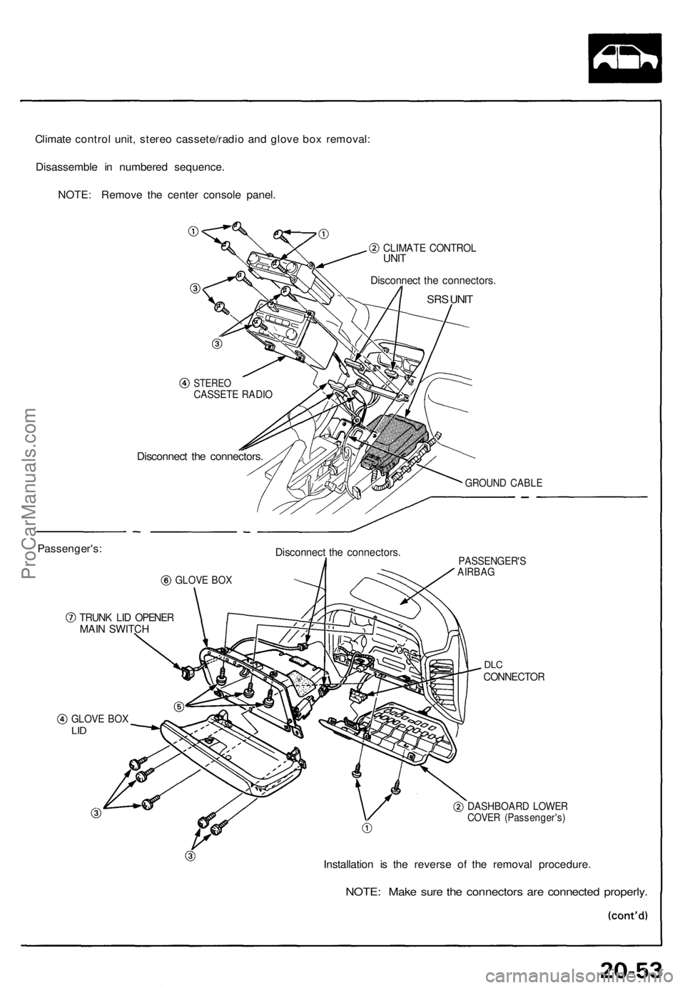
Climate control unit, stereo cassete/radio and glove box removal:
Disassemble in numbered sequence.
NOTE: Remove the center console panel.
CLIMATE CONTROL
UNIT
Disconnect the connectors.
SRS UNIT
Passenger's:
STEREO
CASSETE RADIO
Disconnect the connectors.
GROUND CABLE
GLOVE BOX
Disconnect the connectors.
TRUNK LID OPENER
MAIN SWITCH
PASSENGER'S
AIRBAG
DLC
CONNECTOR
GLOVE BOX
LID
DASHBOARD LOWER
COVER (Passenger's)
Installation is the reverse of the removal procedure.
NOTE: Make sure the connectors are connected properly.ProCarManuals.com
Page 612 of 1640
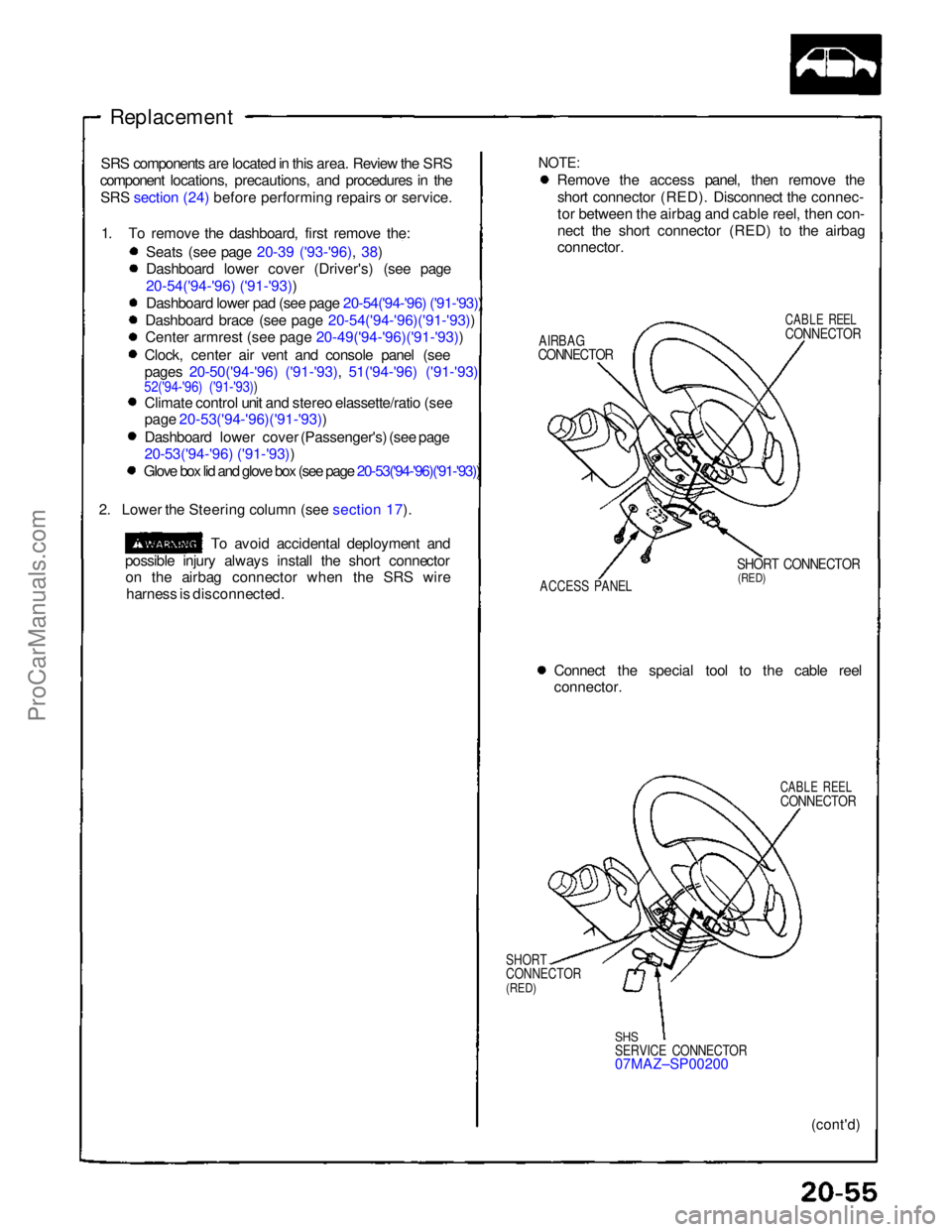
Replacement
NOTE:
Remove the access panel, then remove the
short connector (RED). Disconnect the connec-
tor between the airbag and cable reel, then con-
nect the short connector (RED) to the airbag
connector.
AIRBAG
CONNECTOR
CABLE REEL
CONNECTOR
ACCESS PANEL
SHORT CONNECTOR
(RED)
Connect the special tool to the cable reel
connector.
CABLE REEL
CONNECTOR
SHORT
CONNECTOR
(RED)
SHS
SERVICE CONNECTOR
07MAZ–SP00200
(cont'd)
SRS components are located in this area. Review the SRS
component locations, precautions, and procedures in the
SRS section (24) before performing repairs or service.
1. To remove the dashboard, first remove the: Seats (see page 20-39 ('93-'96), 38)
Dashboard lower cover (Driver's) (see page
20-54('94-'96) ('91-'93))
Dashboard lower pad (see page 20-54('94-'96) ('91-'93))
Dashboard brace (see page 20-54('94-'96)('91-'93))
Cente
r
armrest (see page 20-49('94-'96)('91-'93))
Clock, center air vent and console panel (see
pages 20-50('94-'96) ('91-'93), 51('94-'96) ('91-'93)
52('94-'96) ('91-'93))
Climate control unit and stereo elassette/ratio (see
page 20-53('94-'96)('91-'93))
Dashboard lower cover (Passenger's) (see page
20-53('94-'96) ('91-'93))
Glove box lid and glove box (see page 20-53('94-'96)('91-'93))
2. Lower the Steering column (see section 17).
To avoid accidental deployment and
possible injury always install the short connector on the airbag connector when the SRS wire
harness is disconnected.ProCarManuals.com
Page 830 of 1640
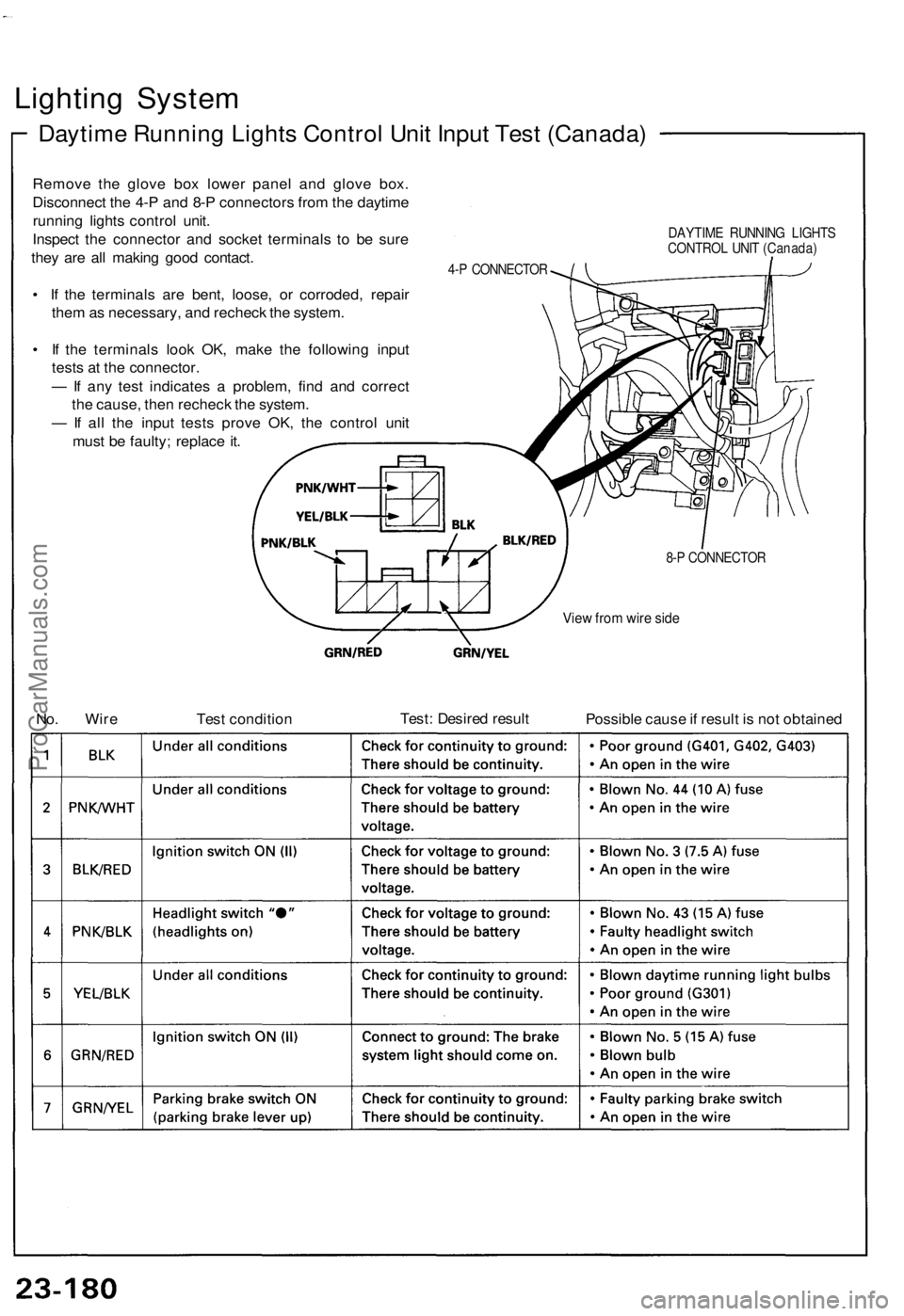
Lighting System
Daytime Running Lights Control Unit Input Test (Canada)
Remove the glove box lower panel and glove box.
Disconnect the 4-P and 8-P connectors from the daytime
running lights control unit.
Inspect the connector and socket terminals to be sure
they are all making good contact.
• If the terminals are bent, loose, or corroded, repair
them as necessary, and recheck the system.
• If the terminals look OK, make the following input
tests at the connector.
— If any test indicates a problem, find and correct
the cause, then recheck the system.
— If all the input tests prove OK, the control unit
must be faulty; replace it.
DAYTIME RUNNING LIGHTS
CONTROL UNIT (Canada)
4-P CONNECTOR
View from wire side
No. Wire
Test condition
Test: Desired result
Possible cause if result is not obtained
8-P CONNECTORProCarManuals.com
Page 850 of 1640
(95-96 Models)
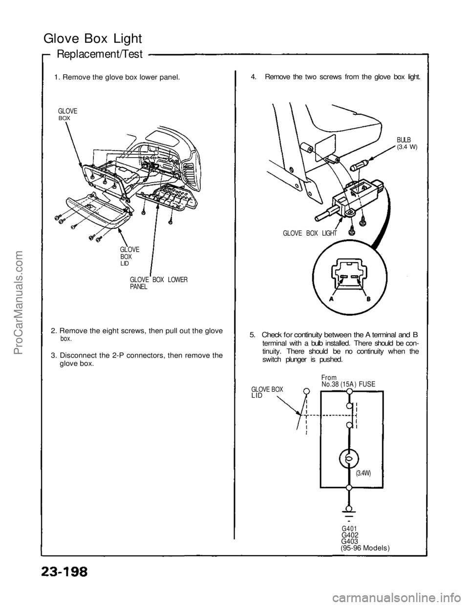
Glove Box Light
1
.
Remove the glove box lower panel.
GLOVE
BOX
GLOVE BOX LOWER
PANEL
2
.
Remove the eight screws, then pull out the glove
box
.
3
.
Disconnect the 2-P connectors, then remove theglov
e
box.
4. Remove the two screws from the glove box light.
BULB
(3.4
W)
5. Check for continuity between the A terminal and B
terminal with a bulb installed. There should be con-
tinuity. There should be no continuity when the
switch plunger is pushed.
GLOVE BOX
LID
From
No.38 (15A ) FUSE
G401
G402
G403
Replacement/Test
GLOVE
BOX
LID
GLOVE BOX LIGHT
(3.4W)ProCarManuals.com
Page 894 of 1640
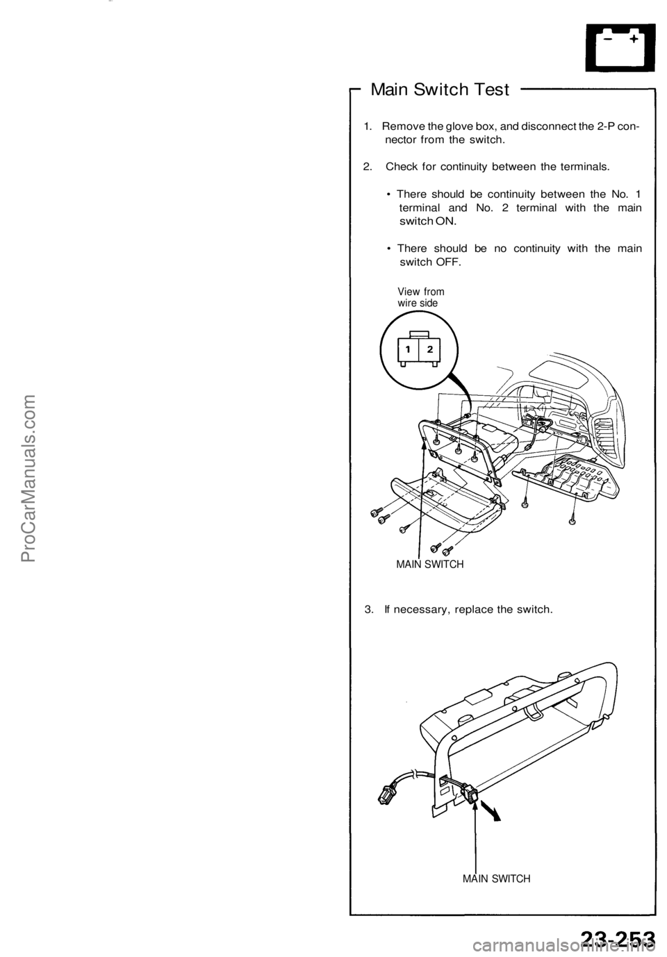
Main Switch Test
1. Remove the glove box, and disconnect the 2-P con-
nector from the switch.
2. Check for continuity between the terminals.
• There should be continuity between the No. 1
terminal and No. 2 terminal with the main
switch ON.
• There should be no continuity with the main
switch OFF.
View from
wire side
MAIN SWITCH
3. If necessary, replace the switch.
MAIN SWITCHProCarManuals.com
Page 903 of 1640
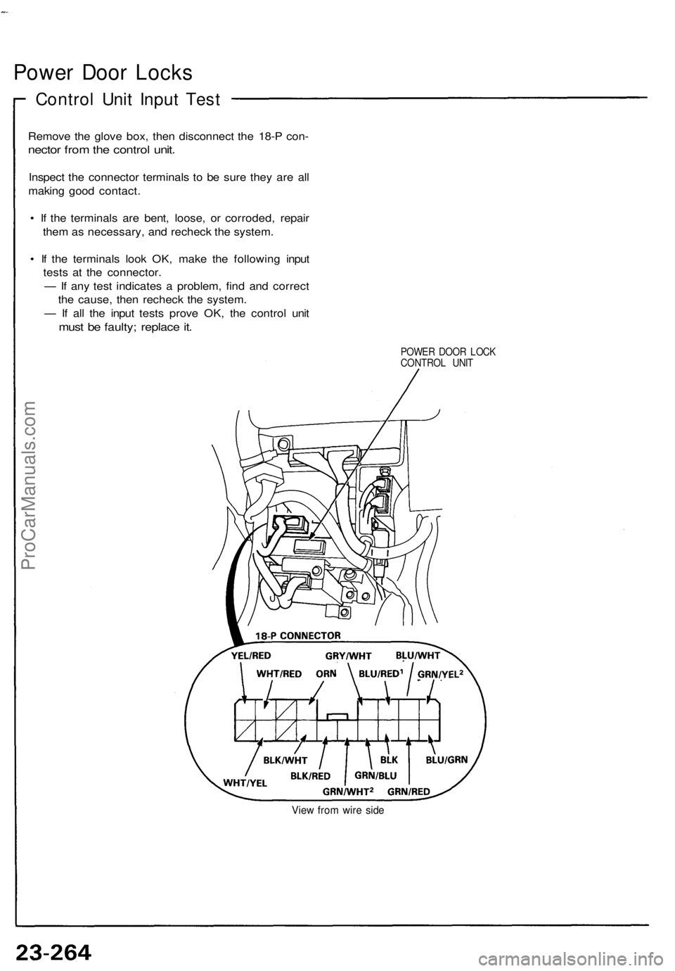
Power Door Locks
Control Unit Input Test
Remove the glove box, then disconnect the 18-P con-
nector from the control unit.
Inspect the connector terminals to be sure they are all
making good contact.
• If the terminals are bent, loose, or corroded, repair
them as necessary, and recheck the system.
• If the terminals look OK, make the following input
tests at the connector.
— If any test indicates a problem, find and correct
the cause, then recheck the system.
— If all the input tests prove OK, the control unit
must be faulty; replace it.
POWER DOOR LOCK
CONTROL UNIT
View from wire sideProCarManuals.com
Page 951 of 1640
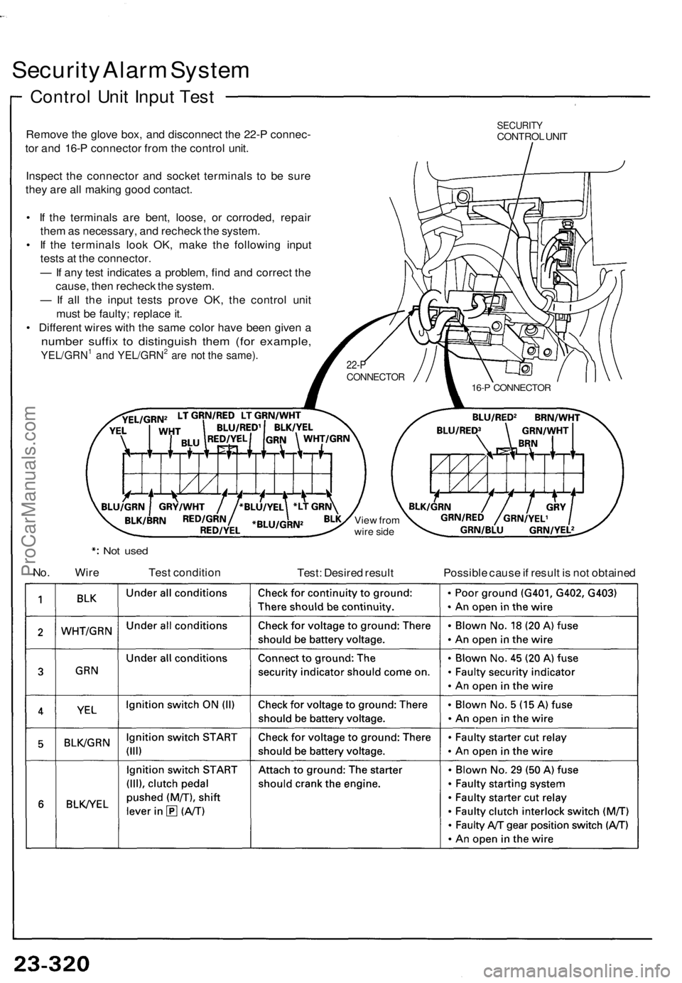
Security Alarm System
Control Unit Input Test
Remove the glove box, and disconnect the 22-P connec-
tor and 16-P connector from the control unit.
Inspect the connector and socket terminals to be sure
they are all making good contact.
• If the terminals are bent, loose, or corroded, repair
them as necessary, and recheck the system.
• If the terminals look OK, make the following input
tests at the connector.
— If any test indicates a problem, find and correct the
cause, then recheck the system.
— If all the input tests prove OK, the control unit
must be faulty; replace it.
• Different wires with the same color have been given a
number suffix to distinguish them (for example,
YEL/GRN1 and YEL/GRN2 are not the same).
SECURITY
CONTROL UNIT
View from
wire side
Not used
No. Wire
Test condition
Test: Desired result
Possible cause if result is not obtained
22-P
CONNECTOR
16-P CONNECTORProCarManuals.com