horn ACURA NSX 1991 Service Repair Manual
[x] Cancel search | Manufacturer: ACURA, Model Year: 1991, Model line: NSX, Model: ACURA NSX 1991Pages: 1640, PDF Size: 60.48 MB
Page 245 of 1640
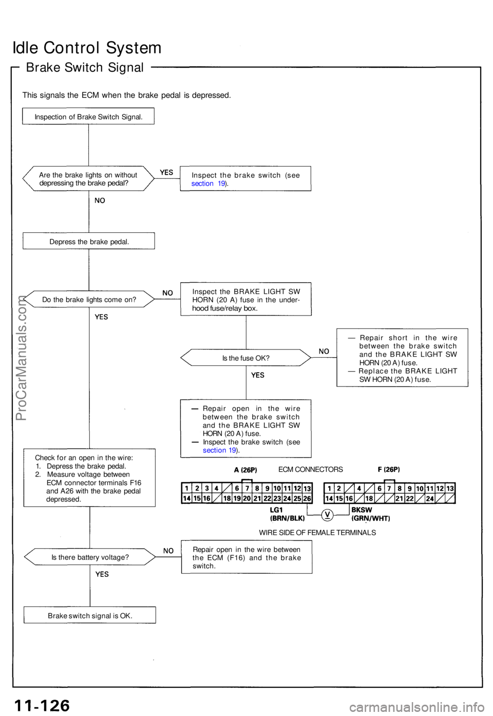
Idle Contro l Syste m
Brake Switc h Signa l
This signal s th e EC M whe n th e brak e peda l i s depressed .
Are th e brak e light s o n withou tdepressin g th e brak e pedal ?Inspec t th e brak e switc h (se e
sectio n 19 ).
Depres s th e brak e pedal .
D o th e brak e light s com e on ?
Is th e fus e OK ?
Chec k fo r a n ope n in th e wire :
1 . Depres s th e brak e pedal .
2 . Measur e voltag e betwee n
EC M connecto r terminal s F1 6
an d A2 6 wit h th e brak e peda l
depressed . —
Repai r shor t i n th e wir e
betwee n th e brak e switc h
an d th e BRAK E LIGH T S W
HOR N (2 0 A ) fuse .
— Replac e th e BRAK E LIGH T
S W HOR N (2 0 A ) fuse .
WIR E SID E O F FEMAL E TERMINAL S
I s ther e batter y voltage ? Repai
r ope n i n th e wir e betwee n
th e EC M (F16 ) an d th e brak e
switch .
Inspectio
n o f Brak e Switc h Signal .
Inspect th e BRAK E LIGH T S W
HORN (20 A ) fus e i n th e under -
hood fuse/rela y box .
Repai r ope n i n th e wir e
betwee n th e brak e switc h
an d th e BRAK E LIGH T S W
HOR N (2 0 A ) fuse .
Inspec t th e brak e switc h (se e
sectio n 19 ).
ECM CONNECTOR S
Brak e switc h signa l i s OK .
ProCarManuals.com
Page 427 of 1640
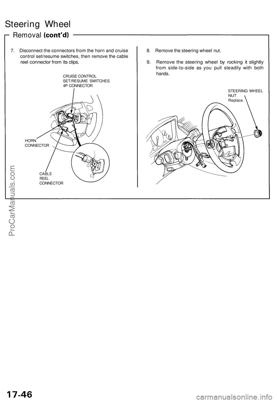
Steering Wheel
Removal
7. Disconnect the connectors from the horn and cruise
control set/resume switches, then remove the cable
reel connector from its clips.
CRUISE CONTROL
SET/RESUME SWITCHES
4P CONNECTOR
HORN
CONNECTOR
CABLE
REEL
CONNECTOR
8. Remove the steering wheel nut.
9. Remove the steering wheel by rocking it slightly
from side-to-side as you pull steadily with both
hands.
STEERING WHEEL
NUT
Replace.ProCarManuals.com
Page 429 of 1640
Installation
NOTE: Before installing the steering wheel, make sure
the front wheels are straight ahead.
CAUTION:
• Be sure to install the harness wires so that they are
not pinched or interfering with other car parts.
• Do not replace the original steering wheel with any
other design, since it will make it impossible to prop-
erly install the airbag. (Use only genuine Honda
replacement parts.)
• After reassembly, confirm that the wheels are still
straight ahead and that steering wheel spoke angle
is correct. If minor spoke angle adjustment is neces-
sary, adjust the tie-rods only. Do not remove and
reposition the steering wheel.
Confirm that the airbag assembly is securely
attached to the steering wheel; otherwise, severe per-
sonal injury could result during later airbag deploy-
ment.
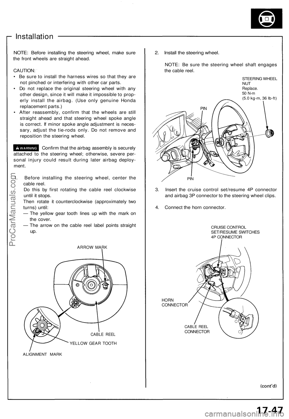
1. Before installing the steering wheel, center the
cable reel.
Do this by first rotating the cable reel clockwise
until it stops.
Then rotate it counterclockwise (approximately two
turns) until:
— The yellow gear tooth lines up with the mark on
the cover.
— The arrow on the cable reel label points straight
up.
ARROW MARK
CABLE REEL
YELLOW GEAR TOOTH
ALIGNMENT MARK
2. Install the steering wheel.
NOTE: Be sure the steering wheel shaft engages
the cable reel.
STEERING WHEEL
NUT
Replace.
50 N-m
(5.0 kg-m, 36 Ib-ft)
PIN
3. Insert the cruise control set/resume 4P connector
and airbag 3P connector to the steering wheel clips.
4. Connect the horn connector.
CRUISE CONTROL
SET/RESUME SWITCHES
4P CONNECTOR
HORN
CONNECTOR
CABLE REEL
CONNECTOR
PINProCarManuals.com
Page 430 of 1640
Steering Wheel
Installation
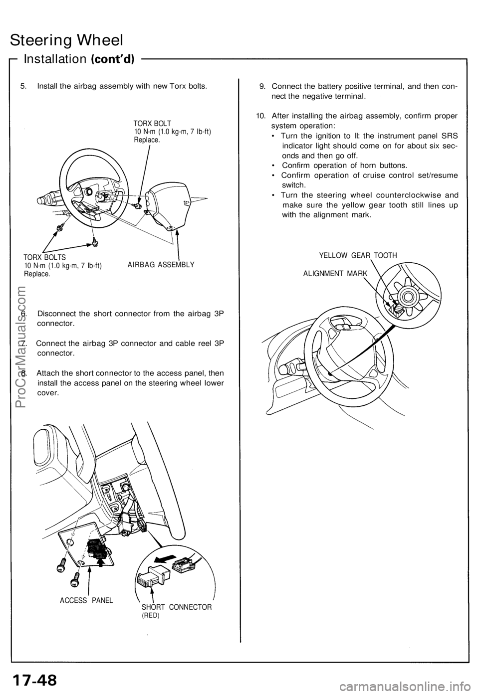
5. Install the airbag assembly with new Torx bolts.
TORX BOLT
10 N-m (1.0 kg-m, 7 Ib-ft)
Replace.
TORX BOLTS
10 N-m (1.0 kg-m, 7 Ib-ft)
Replace.
AIRBAG ASSEMBLY
6. Disconnect the short connector from the airbag 3P
connector.
7. Connect the airbag 3P connector and cable reel 3P
connector.
8. Attach the short connector to the access panel, then
install the access panel on the steering wheel lower
cover.
ACCESS PANEL
SHORT CONNECTOR
(RED)
9. Connect the battery positive terminal, and then con-
nect the negative terminal.
10. After installing the airbag assembly, confirm proper
system operation:
• Turn the ignition to II: the instrument panel SRS
indicator light should come on for about six sec-
onds and then go off.
• Confirm operation of horn buttons.
• Confirm operation of cruise control set/resume
switch.
• Turn the steering wheel counterclockwise and
make sure the yellow gear tooth still lines up
with the alignment mark.
YELLOW GEAR TOOTH
ALIGNMENT MARKProCarManuals.com
Page 615 of 1640
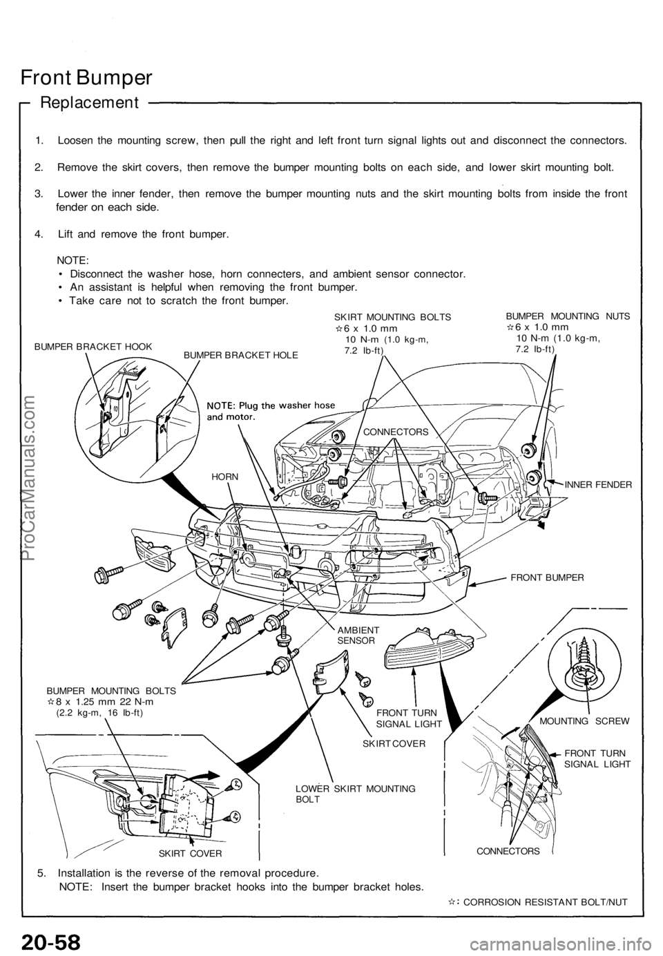
Front Bumpe r
Replacemen t
1. Loose n th e mountin g screw , the n pul l th e righ t an d lef t fron t tur n signa l light s ou t an d disconnec t th e connectors .
2 . Remov e th e skir t covers , the n remov e th e bumpe r mountin g bolt s o n eac h side , an d lowe r skir t mountin g bolt .
3 . Lowe r th e inne r fender , the n remov e th e bumpe r mountin g nut s an d th e skir t mountin g bolt s fro m insid e th e fron t
fende r o n eac h side .
4. Lif t an d remov e th e fron t bumper .
NOTE:
• Disconnec t th e washe r hose , hor n connecters , an d ambien t senso r connector .
• A n assistan t i s helpfu l whe n removin g th e fron t bumper .
• Tak e car e no t t o scratc h th e fron t bumper .
BUMPER BRACKE T HOO K
INNER FENDE R
FRON T TUR N
SIGNA L LIGH T
5. Installatio n i s th e revers e o f th e remova l procedure .
NOTE : Inser t th e bumpe r bracke t hook s int o th e bumpe r bracke t holes .
CONNECTOR S
CORROSIO N RESISTAN T BOLT/NU T
BUMPE
R MOUNTIN G BOLT S
8 x 1.2 5 mm 2 2 N- m(2.2 kg-m , 1 6 Ib-ft ) AMBIEN
T
SENSOR
FRONT BUMPE R
HORN
CONNECTOR S
FRONT TUR N
SIGNA L LIGH T
SKIR T COVE R
LOWE R SKIR T MOUNTIN G
BOLT
MOUNTIN G SCRE W
SKIR T COVE R SKIR
T MOUNTIN G BOLT S
6 x 1. 0 m m10 N- m (1. 0 kg-m ,7.2 Ib-ft ) BUMPE
R MOUNTIN G NUT S
6 x 1. 0 m m10 N- m (1. 0 kg-m ,7.2 Ib-ft )
BUMPE R BRACKE T HOL E
ProCarManuals.com
Page 732 of 1640
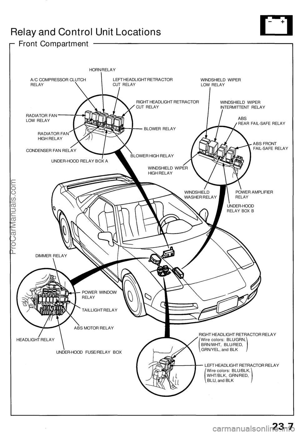
Relay and Control Unit Locations
Front Compartment
HORN RELAY
A/C COMPRESSOR CLUTCH
RELAY
RADIATOR FAN
LOW RELAY
RADIATOR FAN
HIGH RELAY
CONDENSER FAN RELAY
UNDER-HOOD RELAY BOX A
LEFT HEADLIGHT RETRACTOR
CUT RELAY
WINDSHIELD WIPER
LOW RELAY
WINDSHIELD WIPER
INTERMITTENT RELAY
POWER AMPLIFIER
RELAY
ABS
REAR FAIL-SAFE RELAY
ABS FRONT
FAIL-SAFE RELAY
HEADLIGHT RELAY
RIGHT HEADLIGHT RETRACTOR RELAY
Wire colors: BLU/GRN,
BRN/WHT, BLU/RED,
GRN/YEL, and BLK
LEFT HEADLIGHT RETRACTOR RELAY
Wire colors: BLU/BLK,
WHT/BLK, GRN/RED,
BLU,
and BLK
RIGHT HEADLIGHT RETRACTOR
CUT RELAY
BLOWER RELAY
BLOWER HIGH RELAY
WINDSHIELD WIPER
HIGH RELAY
WINDSHIELD
WASHER RELAY
UNDER-HOOD
RELAY BOX B
DIMMER RELAY
POWER WINDOW
RELAY
TAILLIGHT RELAY
ABS MOTOR RELAY
UNDER-HOOD FUSE/RELAY BOXProCarManuals.com
Page 888 of 1640
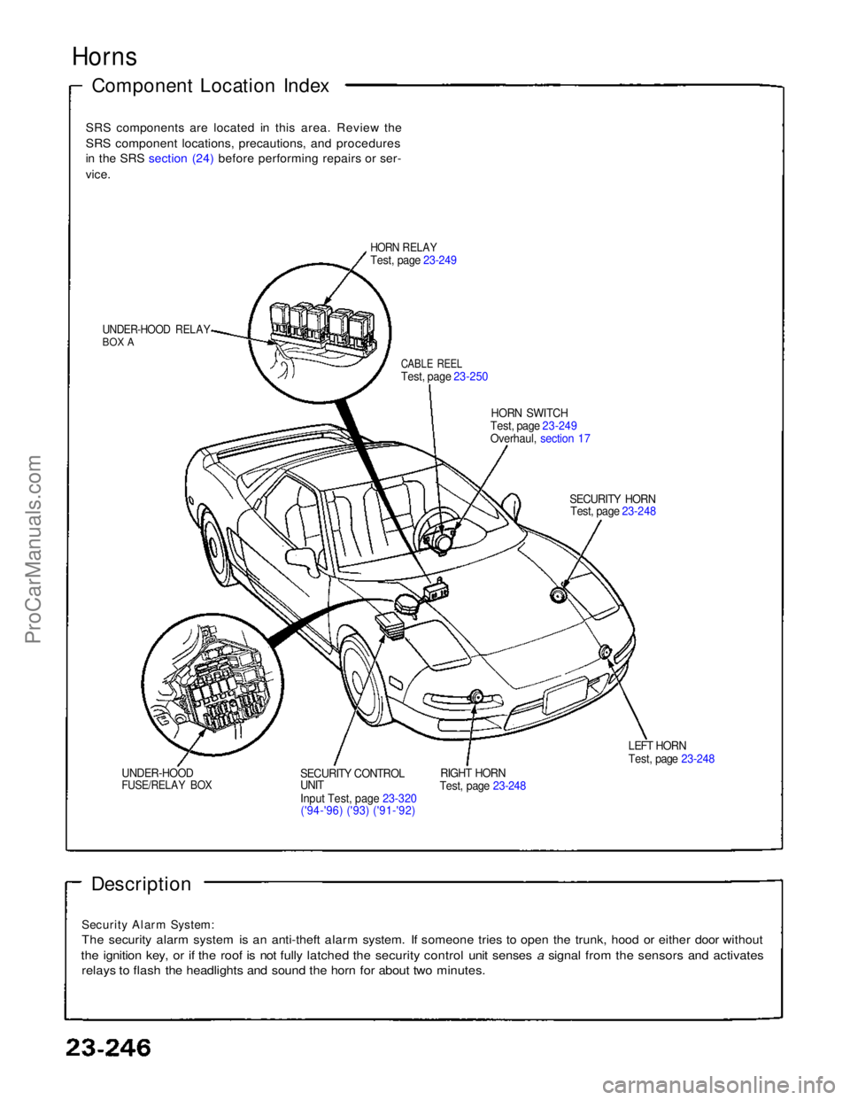
Horns
Component Location Index
SRS components are located in this area. Review the
SRS component locations, precautions, and procedures
in the SRS section (24) before performing repairs or ser-
vice.
HORN RELAY
Test, page 23-249
UNDER-HOOD RELAY
BOX A
CABLE REEL
Test, page 23-250
HORN SWITCH
Test, page 23-249
Overhaul, section 17
SECURITY HORNTest, page 23-248
LEFT HORN
Test, page 23-248
RIGHT HORN
Test, page 23-248
SECURITY CONTROL
UNIT
Inpu
t
Test, page 23-320
('94-'96) ('93) ('91-'92)
UNDER-HOOD
FUSE/RELAY BOX
Description
Security Alarm System:
The security alarm system is an anti-theft alarm system. If someone tries to open the trunk, hood or either door without
the ignition key, or if the roof is not fully latched the security control unit senses a signal from the sensors and activates
relays to flash the headlights and sound the horn for about two minutes.ProCarManuals.com
Page 889 of 1640
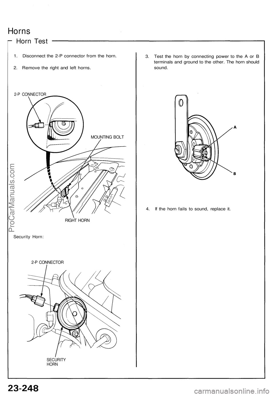
Horns
Horn Tes t
1. Disconnec t th e 2- P connecto r fro m th e horn .
2 . Remov e th e righ t an d lef t horns .
2-P CONNECTO R
RIGHT HOR N
Securit y Horn :
2-P CONNECTO R
SECURITY
HOR N
3. Tes t th e hor n b y connectin g powe r t o th e A or B
terminal s an d groun d t o th e other . Th e hor n shoul d
sound .
4 . I f th e hor n fail s t o sound , replac e it .
MOUNTIN G BOL T
ProCarManuals.com
Page 891 of 1640
Horns
Switc h Tes t (cont'd )
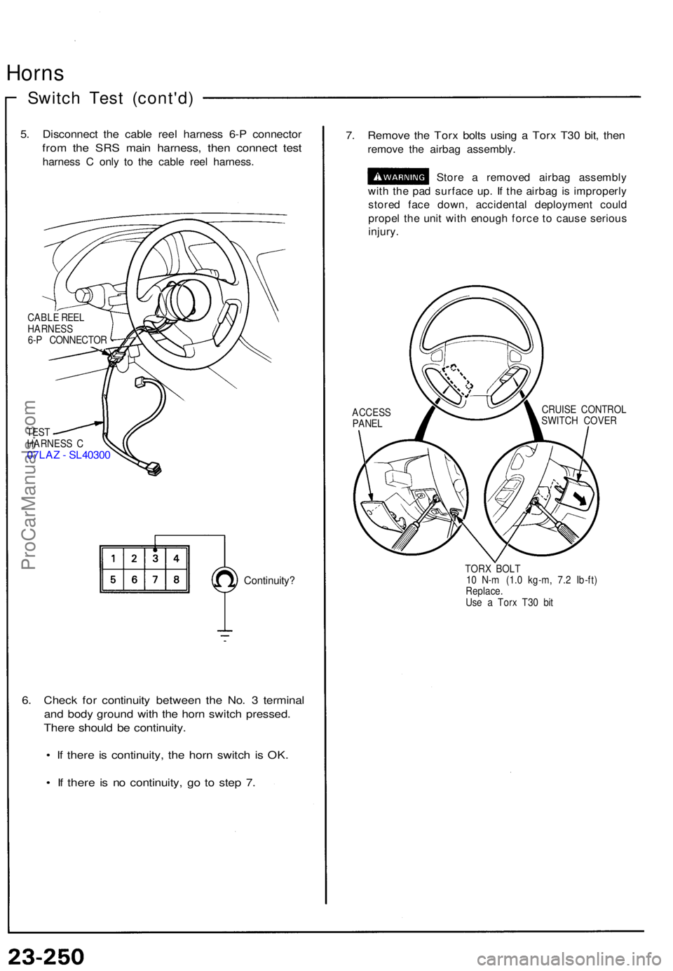
5. Disconnec t th e cabl e ree l harnes s 6- P connecto r
from th e SR S mai n harness , the n connec t tes t
harnes s C onl y t o th e cabl e ree l harness .
CABLE REE L
HARNES S
6- P CONNECTO R
TES T
HARNES S C
07LA Z - SL4030 0
Continuity ?
6. Chec k fo r continuit y betwee n th e No . 3 termina l
and bod y groun d wit h th e hor n switc h pressed .
There shoul d b e continuity .
• I f ther e is continuity , th e hor n switc h i s OK .
• I f ther e i s n o continuity , g o t o ste p 7 .
7. Remov e th e Tor x bolt s usin g a Tor x T3 0 bit , the n
remov e th e airba g assembly .
Stor e a remove d airba g assembl y
wit h th e pa d surfac e up . I f th e airba g is improperl y
store d fac e down , accidenta l deploymen t coul d
prope l th e uni t wit h enoug h forc e t o caus e seriou s
injury .
ACCES SPANEL
CRUIS E CONTRO L
SWITC H COVE R
TOR X BOL T
1 0 N- m (1. 0 kg-m , 7. 2 Ib-ft )
Replace .
Us e a Tor x T3 0 bi t
ProCarManuals.com
Page 936 of 1640
Troubleshooting
Cruise Control
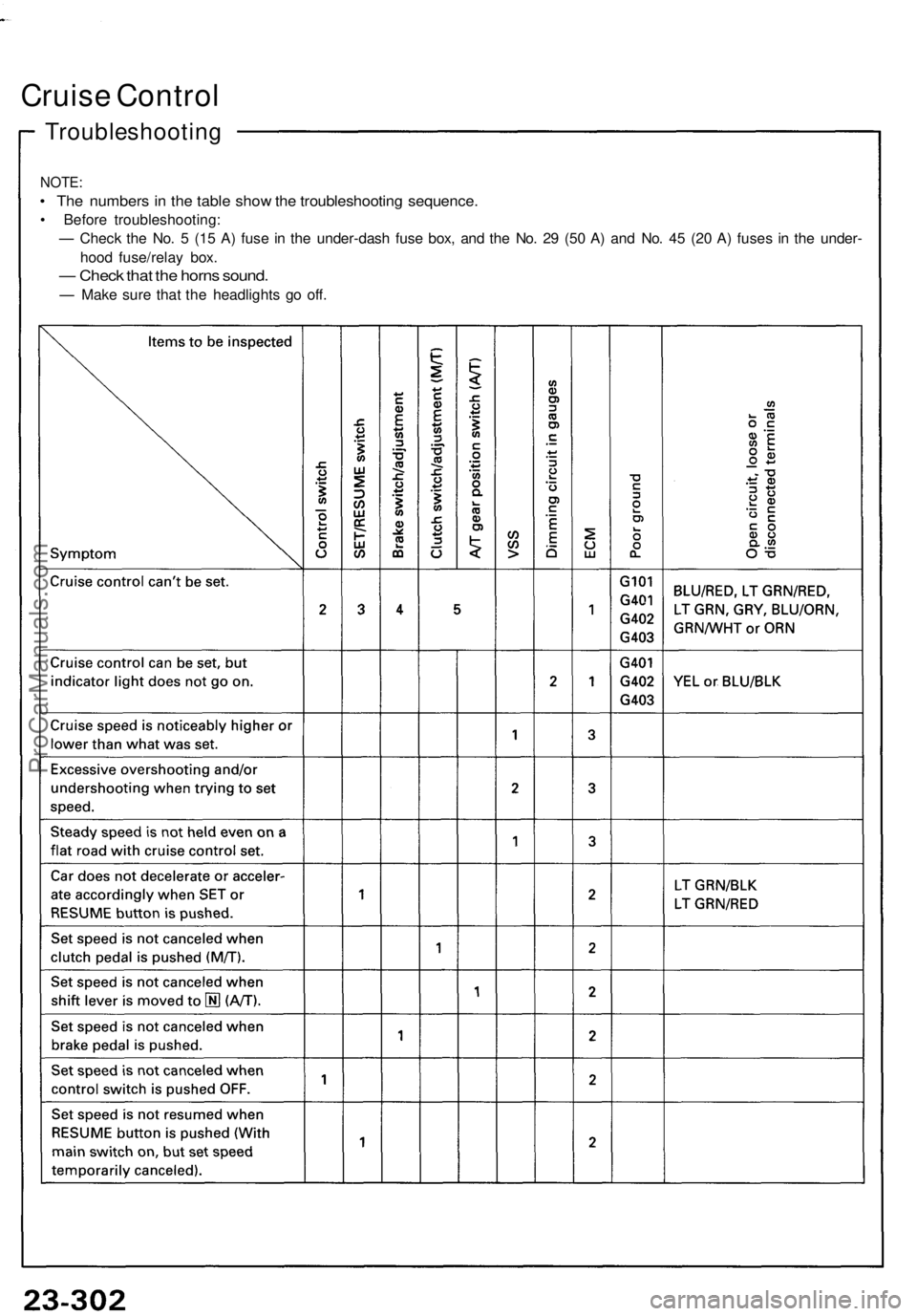
NOTE:
• The numbers in the table show the troubleshooting sequence.
• Before troubleshooting:
— Check the No. 5 (15 A) fuse in the under-dash fuse box, and the No. 29 (50 A) and No. 45 (20 A) fuses in the under-
hood fuse/relay box.
— Check that the horns sound.
— Make sure that the headlights go off.ProCarManuals.com