length ACURA NSX 1991 Service Repair Manual
[x] Cancel search | Manufacturer: ACURA, Model Year: 1991, Model line: NSX, Model: ACURA NSX 1991Pages: 1640, PDF Size: 60.48 MB
Page 294 of 1640
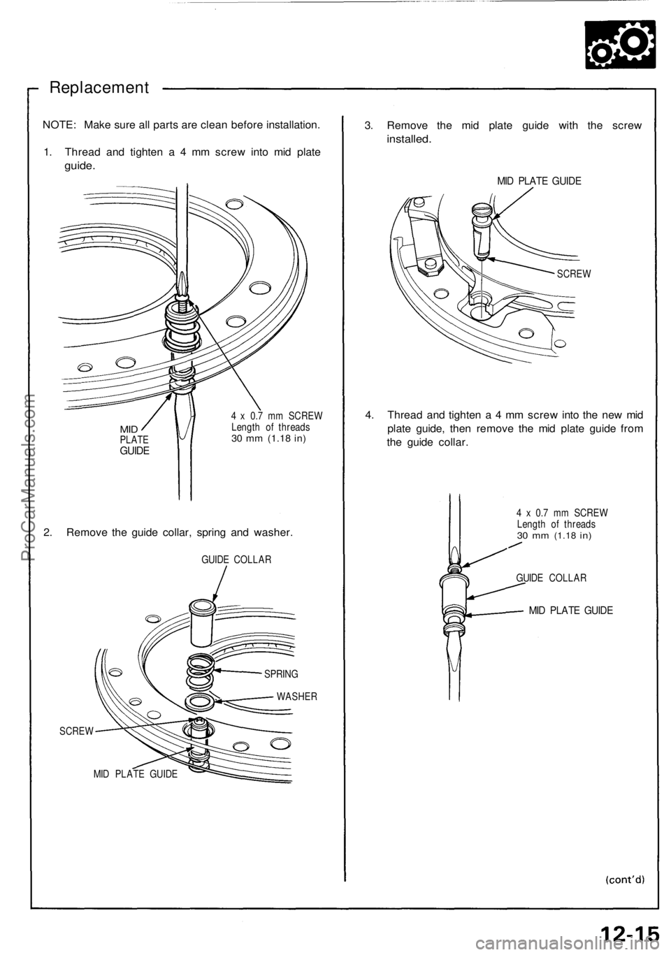
Replacement
NOTE: Make sure all parts are clean before installation.
1. Thread and tighten a 4 mm screw into mid plate
guide.
MID
PLATE
GUIDE
4 x 0.7 mm SCREW
Length of threads
30 mm
(1.18
in)
2. Remove the guide collar, spring and washer.
GUIDE COLLAR
SCREW
MID PLATE GUIDE
3. Remove the mid plate guide with the screw
installed.
MID PLATE GUIDE
SCREW
4. Thread and tighten a 4 mm screw into the new mid
plate guide, then remove the mid plate guide from
the guide collar.
4 x 0.7 mm SCREW
Length of threads
30 mm
(1.18
in)
GUIDE COLLAR
MID PLATE GUIDE
SPRING
WASHERProCarManuals.com
Page 444 of 1640
Steering Gearbo x
Inspectio n
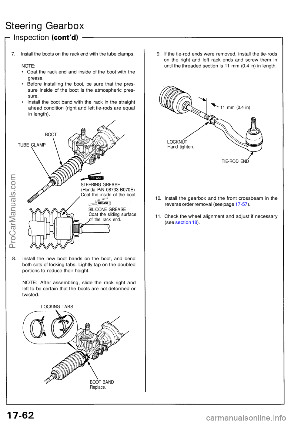
7. Instal l th e boot s o n th e rac k en d wit h th e tub e clamps .
NOTE:
• Coa t th e rac k en d an d insid e o f th e boo t wit h th e
grease .
• Befor e installin g th e boot , b e sur e tha t th e pres -
sur e insid e o f th e boo t i s th e atmospheri c pres -
sure.
• Instal l th e boo t ban d wit h th e rac k i n th e straigh t
ahea d conditio n (righ t an d lef t tie-rod s ar e equa l
i n length) .
BOOT
TUBE CLAM P
STEERIN G GREAS E(Honda P/ N 08733-B070E )Coat th e insid e o f th e boot .
SILICON E GREAS ECoat th e slidin g surfac eof th e rac k end .
8. Instal l th e ne w boo t band s o n th e boot , an d ben d
bot h set s o f lockin g tabs . Lightl y ta p o n th e double d
portion s t o reduc e thei r height .
NOTE : Afte r assembling , slid e th e rac k righ t an d
lef t t o b e certai n tha t th e boot s ar e no t deforme d o r
twisted .
LOCKIN G TAB S
BOOT BAN DReplace .
9. I f th e tie-ro d end s wer e removed , instal l th e tie-rod s
o n th e righ t an d lef t rac k end s an d scre w the m in
unti l th e threade d sectio n is 1 1 m m (0. 4 in ) i n length .
11 m m (0. 4 in)
LOCKNU THand tighten .
TIE-RO D EN D
10. Instal l th e gearbo x an d th e fron t crossbea m in th e
revers e orde r remova l (se e pag e 17-57 ).
11 . Chec k th e whee l alignmen t an d adjus t i f necessar y
(se e sectio n 18 ).
ProCarManuals.com
Page 457 of 1640
Wheel Alignmen t
Rear Whee l Alignmen t Adjustin g Procedur e
NOTE:
• NSX/NSX- T fou r whee l alignmen t require s th e us e o f
equipmen t designe d specificall y fo r fou r whee l
independen t suspension s an d capabl e o f immediat e
feedback.
1. Driv e th e ca r o n th e alignmen t rack .
2 . Chec k th e tir e pressur e an d rid e heigh t a s describe d
on pag e 18-6 .
3. Cente r th e steerin g wheel .
Toe
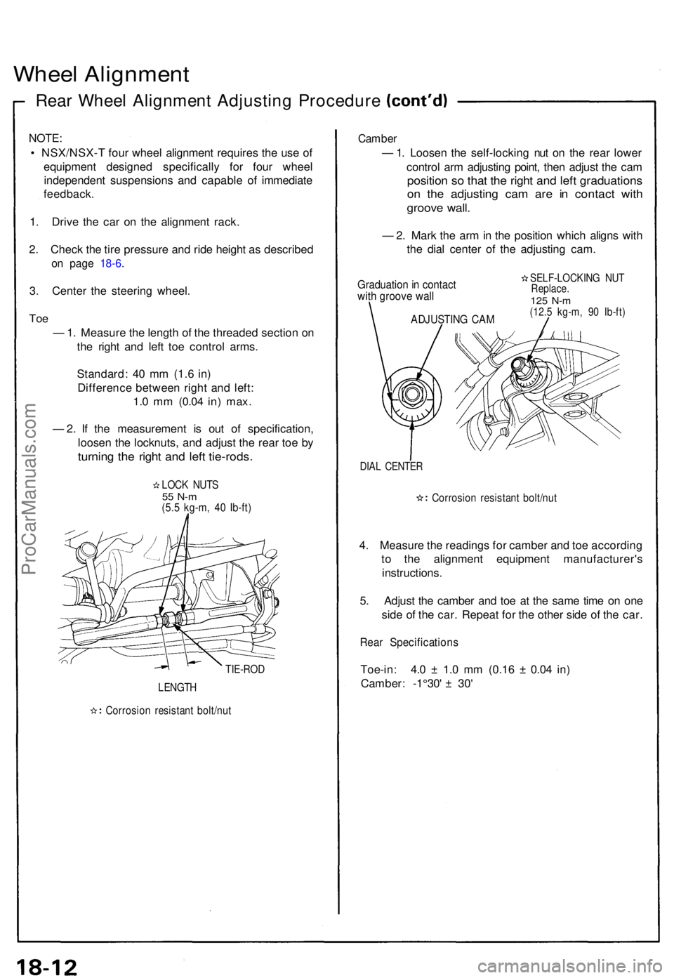
— 1. Measur e th e lengt h o f th e threade d sectio n o n
th e righ t an d lef t to e contro l arms .
Standard : 4 0 m m (1. 6 in )
Differenc e betwee n righ t an d left :
1.0 m m (0.0 4 in) max .
— 2. I f th e measuremen t i s ou t o f specification ,
loose n th e locknuts , an d adjus t th e rea r to e b y
turnin g th e righ t an d lef t tie-rods .
LOCK NUT S55 N- m(5.5 kg-m , 4 0 Ib-ft )
TIE-RO D
LENGTH
Corrosio n resistan t bolt/nu t
Camber
— 1. Loose n th e self-lockin g nu t o n th e rea r lowe r
contro l ar m adjustin g point , the n adjus t th e ca m
positio n s o tha t th e righ t an d lef t graduation s
on th e adjustin g ca m ar e i n contac t wit h
groov e wall .
— 2. Mar k th e ar m in th e positio n whic h align s wit h
th e dia l cente r of the adjustin g cam .
Graduatio n in contac twith groov e wall
SELF-LOCKIN G NU TReplace .125 N- m(12. 5 kg-m , 9 0 Ib-ft )
DIAL CENTE R
Corrosio n resistan t bolt/nu t
4. Measur e th e reading s fo r cambe r an d to e accordin g
t o th e alignmen t equipmen t manufacturer' s
instructions .
5 . Adjus t th e cambe r an d to e a t th e sam e tim e o n on e
sid e o f th e car . Repea t fo r th e othe r sid e of the car .
Rear Specification s
Toe-in: 4. 0 ± 1. 0 m m (0.1 6 ± 0.0 4 in )
Camber : - 1°30 ' ± 30'
ADJUSTIN G CA M
ProCarManuals.com
Page 643 of 1640
Roof
Roof Side Seal/Retainer Replacement
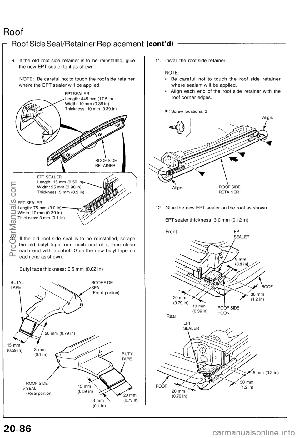
9. If the old roof side retainer is to be reinstalled, glue
the new EPT sealer to it as shown.
NOTE: Be careful not to touch the roof side retainer
where the EPT sealer will be applied.
EPT SEALER
Length: 445 mm (17.5 in)
Width: 10 mm (0.39 in)
Thickness: 10 mm (0.39 in)
EPT SEALER
Length: 15 mm (0.59 in)
Width: 25 mm (0.98 in)
Thickness: 5 mm (0.2 in)
EPT SEALER
Length: 75 mm (3.0 in)
Width: 10 mm (0.39 in)
Thickness: 3 mm (0.1 in)
10. If the old roof side seal is to be reinstalled, scrape
the old butyl tape from each end of it, then clean
each end with alcohol. Glue the new butyl tape on
each end as shown.
Butyl tape thickness: 0.5 mm (0.02 in)
BUTYL
TAPE
ROOF SIDE
SEAL
(Front portion)
15 mm
(0.59
in)
BUTYL
TAPE
ROOF SIDE
> SEAL
(Rear portion)
3 mm
(0.1
in)
20 mm
(0.79
in)
11. Install the roof side retainer.
NOTE:
• Be careful not to touch the roof side retainer
where sealant will be applied.
• Align each end of the roof side retainer with the
roof corner edges.
Screw locations, 3
Align.
Align.
ROOF SIDE
RETAINER
12. Glue the new EPT sealer on the roof as shown.
EPT sealer thickness: 3.0 mm (0.12 in)
Front:
EPT
SEALER
ROOF
20 mm
(0.79
in)
30 mm
(1.2
in)
10 mm
(0.39
in)
Rear:
ROOF SIDE
HOOK
EPT
SEALER
5 mm
(0.2
in)
ROOF
20 mm
(0.79
in)
30 mm
(1.2
in)
3 mm
(0.1
in)
20 mm
(0.79
in)
15 mm
(0.59
in)
ROOF SIDE
RETAINERProCarManuals.com
Page 753 of 1640
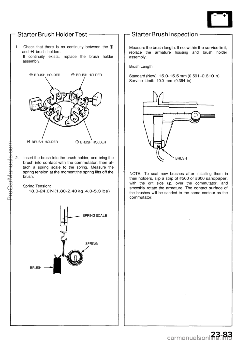
Starter Brush Holder Test
1. Check that there is no continuity between the
and brush holders.
If continuity exists, replace the brush holder
assembly.
BRUSH HOLDER
BRUSH HOLDER
BRUSH HOLDER
2. Insert the brush into the brush holder, and bring the
brush into contact with the commutator, then at-
tach a spring scale to the spring. Measure the
spring tension at the moment the spring lifts off the
brush.
Spring Tension:
18.0-24.0 N (1.80-2.40 kg, 4.0-5.3 Ibs)
SPRING SCALE
BRUSH
SPRING
Starter Brush Inspection
Measure the brush length. If not within the service limit,
replace the armature housing and brush holder
assembly.
Brush Length
Standard (New):
15.0-15.5
mm
(0.591
-0.610
in)
Service Limit: 10.0 mm (0.394 in)
BRUSH
NOTE: To seat new brushes after installing them in
their holders, slip a strip of #500 or #600 sandpaper,
with the grit side up, over the commutator, and
smoothly rotate the armature. The contact surface of
the brushes will be sanded to the same contour as the
commutator.
BRUSH HOLDERProCarManuals.com
Page 774 of 1640
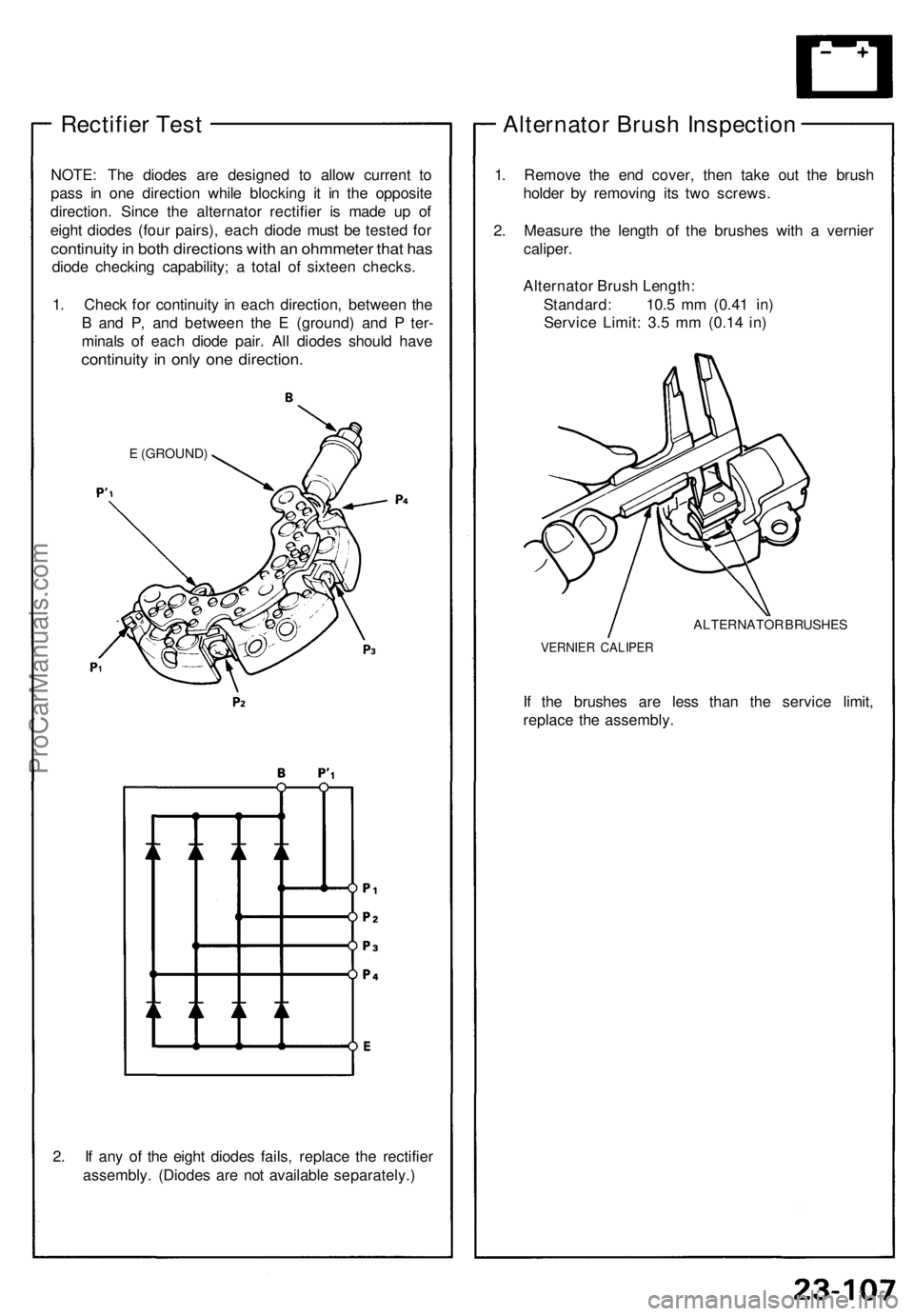
Rectifier Test
NOTE: The diodes are designed to allow current to
pass in one direction while blocking it in the opposite
direction. Since the alternator rectifier is made up of
eight diodes (four pairs), each diode must be tested for
continuity in both directions with an ohmmeter that has
diode checking capability; a total of sixteen checks.
1. Check for continuity in each direction, between the
B and P, and between the E (ground) and P ter-
minals of each diode pair. All diodes should have
continuity in only one direction.
E (GROUND)
2. If any of the eight diodes fails, replace the rectifier
assembly. (Diodes are not available separately.)
Alternator Brush Inspection
1. Remove the end cover, then take out the brush
holder by removing its two screws.
2. Measure the length of the brushes with a vernier
caliper.
Alternator Brush Length:
Standard: 10.5 mm (0.41 in)
Service Limit: 3.5 mm (0.14 in)
ALTERNATOR BRUSHES
VERNIER CALIPER
If the brushes are less than the service limit,
replace the assembly.ProCarManuals.com
Page 1032 of 1640
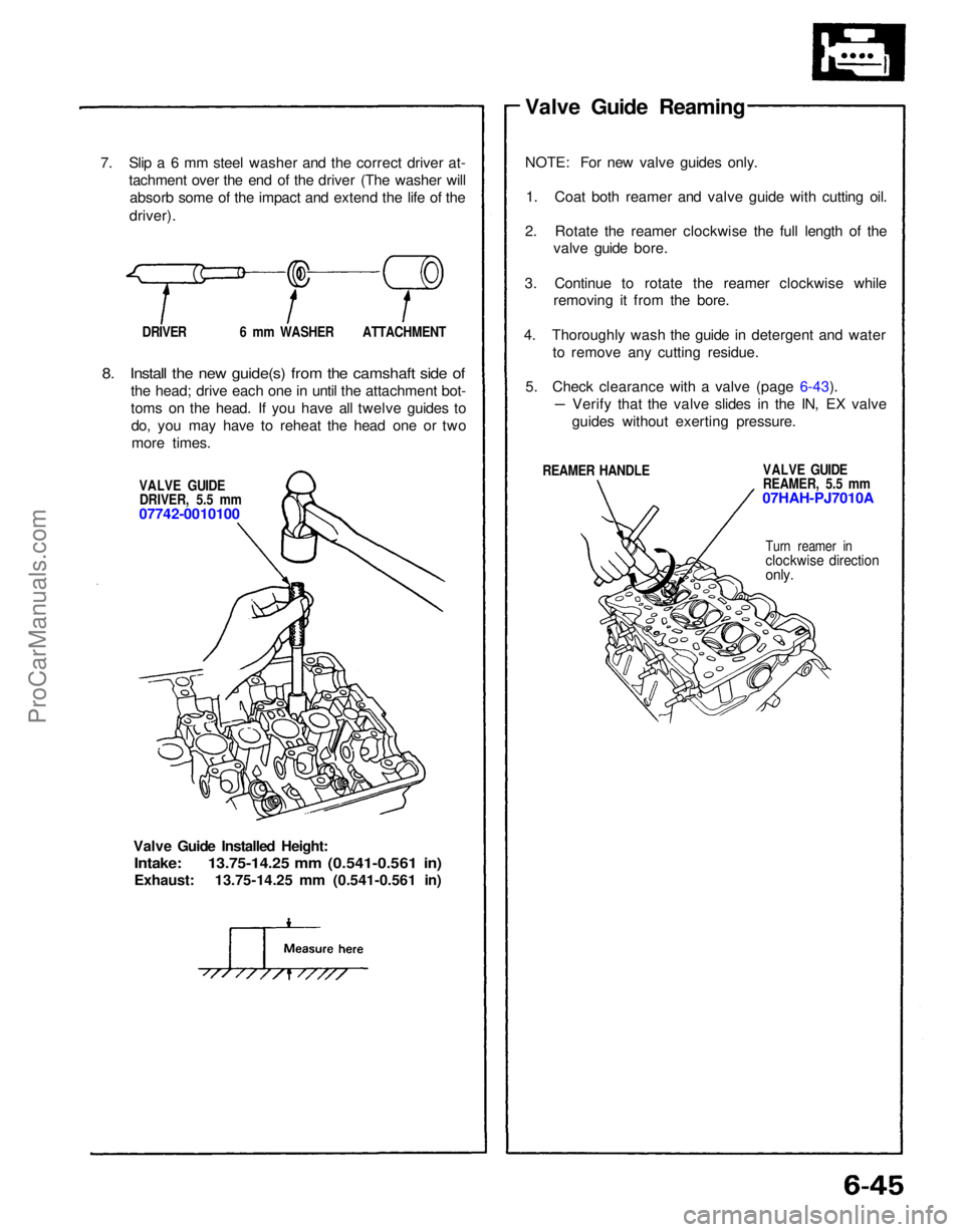
7. Slip a 6 mm steel washer and the correct driver at-
tachment over the end of the driver (The washer willabsorb some of the impact and extend the life of the
driver).
DRIVER 6 mm WASHER ATTACHMENT
8. Install the new guide(s) from the camshaft side of
the head; drive each one in until the attachment bot-
toms on the head. If you have all twelve guides todo, you may have to reheat the head one or twomore times.
VALVE GUIDEDRIVER, 5.5 mm
07742-0010100
Valve Guide Installed Height:
Intake: 13.75-14.25 mm (0.541-0.561 in)
Exhaust: 13.75-14.25 mm (0.541-0.561 in) Valve Guide Reaming
NOTE: For new valve guides only.
1. Coat both reamer and valve guide with cutting oil.
2. Rotate the reamer clockwise the full length of the valve guide bore.
3. Continue to rotate the reamer clockwise while removing it from the bore.
4. Thoroughly wash the guide in detergent and water to remove any cutting residue.
5. Check clearance with a valve (page 6-43).
REAMER HANDLE VALVE GUIDE
REAMER, 5.5 mm
07HAH-PJ7010A
Turn reamer in
clockwise direction
only.
Verify that the valve slides in the IN, EX valve
guides without exerting pressure.ProCarManuals.com
Page 1033 of 1640
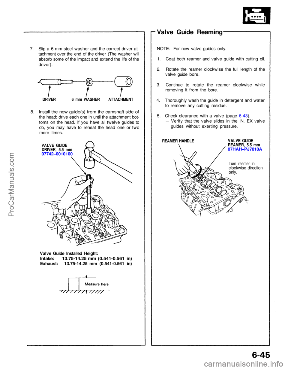
7. Slip a 6 mm steel washer and the correct driver at-
tachment over the end of the driver (The washer willabsorb some of the impact and extend the life of the
driver).
DRIVER 6 mm WASHER ATTACHMENT
8. Install the new guide(s) from the camshaft side of
the head; drive each one in until the attachment bot-
toms on the head. If you have all twelve guides todo, you may have to reheat the head one or twomore times.
VALVE GUIDEDRIVER, 5.5 mm
07742–0010100
Valve Guide Installed Height:
Intake: 13.75-14.25 mm (0.541-0.561 in)
Exhaust: 13.75-14.25 mm (0.541-0.561 in) Valve Guide Reaming
NOTE: For new valve guides only.
1. Coat both reamer and valve guide with cutting oil.
2. Rotate the reamer clockwise the full length of the valve guide bore.
3. Continue to rotate the reamer clockwise while removing it from the bore.
4. Thoroughly wash the guide in detergent and water to remove any cutting residue.
5. Check clearance with a valve (page 6-43).
REAMER HANDLE VALVE GUIDE
REAMER, 5.5 mm
07HAH–PJ7010A
Turn reamer in
clockwise direction
only.
Verify that the valve slides in the IN, EX valve
guides without exerting pressure.ProCarManuals.com
Page 1078 of 1640
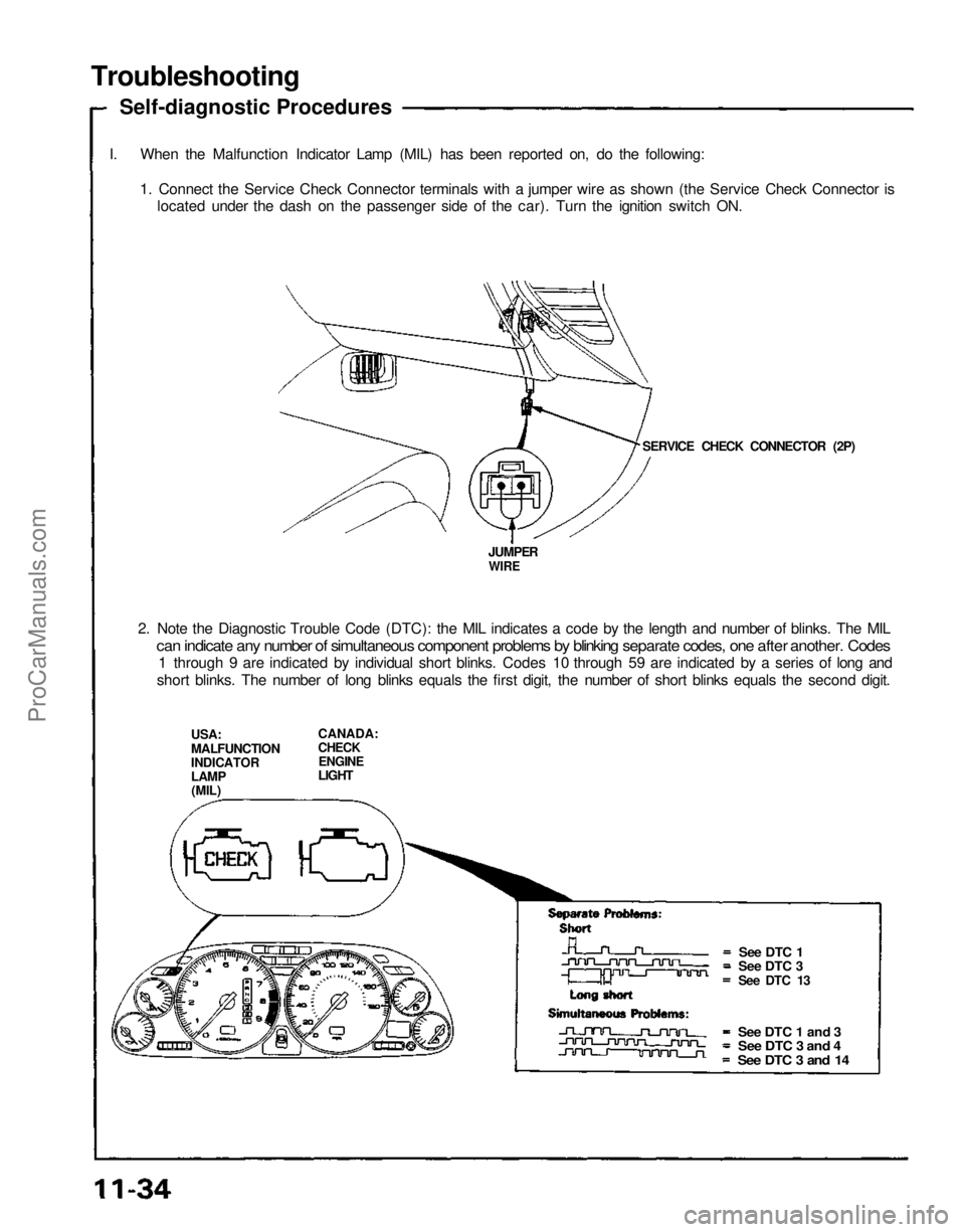
Troubleshooting
Self-diagnostic Procedures
I. When the Malfunction Indicator Lamp (MIL) has been reported on, do the following: 1. Connect the Service Check Connector terminals with a jumper wire as shown (the Service Check Connector islocated under the dash on the passenger side of the car). Turn the ignition switch ON.
SERVICE CHECK CONNECTOR (2P)
JUMPER
WIRE
2. Note the Diagnostic Trouble Code (DTC): the MIL indicates a code by the length and number of blinks. The MIL
can indicate any number of simultaneous component problems by blinking separate codes, one after another. Codes
1 through 9 are indicated by individual short blinks. Codes 10 through 59 are indicated by a series of long and
short blinks. The number of long blinks equals the first digit, the number of short blinks equals the second digit.
USA:
MALFUNCTION
INDICATOR
LAMP
(MIL) CANADA:
CHECK
ENGINE
LIGHT
See DTC 1
See DTC 3
See DTC 13
See DTC 1 and 3
See DTC 3 and 4
See DTC 3 and 14ProCarManuals.com
Page 1248 of 1640
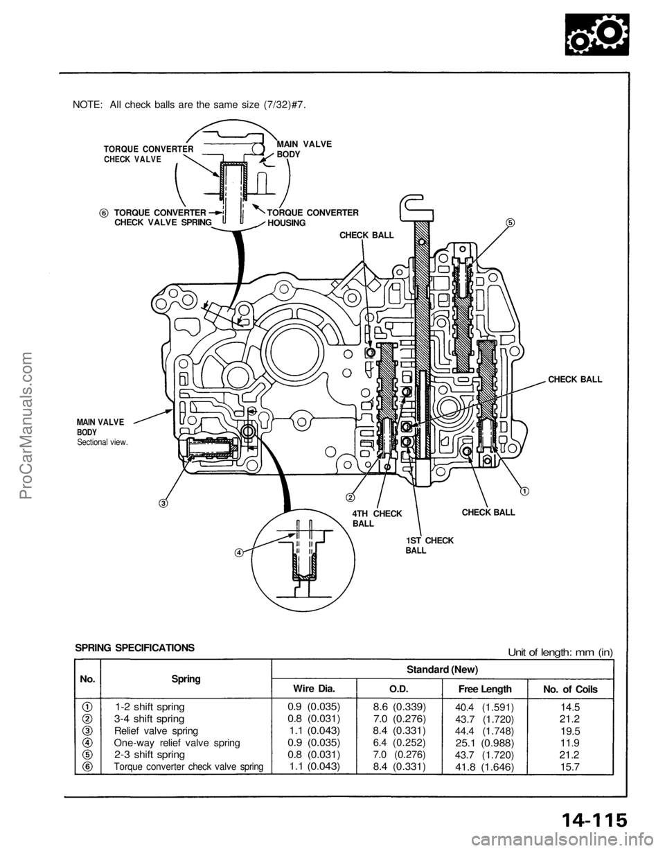
NOTE: All check balls are the same size (7/32)#7.
TORQUE CONVERTER
CHECK VALVE
TORQUE CONVERTER
CHECK VALVE SPRING TORQUE CONVERTER
HOUSING
CHECK BALL
MAIN VALVE
BODY
CHECK BALL
CHECK BALL
1ST CHECK
BALL
4TH CHECK
BALL
Unit of length: mm (in)
SPRING SPECIFICATIONS
Spring
No.
1-2 shift spring
3-4 shift spring
Relief valve spring
One-way relief valve spring
2-3 shift spring
Torque converter check valve spring
Wire Dia.
O.D.Standard (New)
Free Length
0.9 (0.035)
0.8 (0.031)
1.1 (0.043)
0.9 (0.035)
0.8 (0.031)
1.1 (0.043)
8.6 (0.339)
7.0 (0.276)
8.4 (0.331)
6.4 (0.252)
7.0 (0.276)
8.4 (0.331)
40.4 (1.591)
43.7 (1.720)
44.4 (1.748)
25.1 (0.988)
43.7 (1.720)
41.8 (1.646)
No. of Coils
14.5
21.2
19.5
11.9
21.2 15.7
MAIN VALVE
BODY
Sectional view.
ProCarManuals.com