open hood ACURA NSX 1991 Service Repair Manual
[x] Cancel search | Manufacturer: ACURA, Model Year: 1991, Model line: NSX, Model: ACURA NSX 1991Pages: 1640, PDF Size: 60.48 MB
Page 165 of 1640
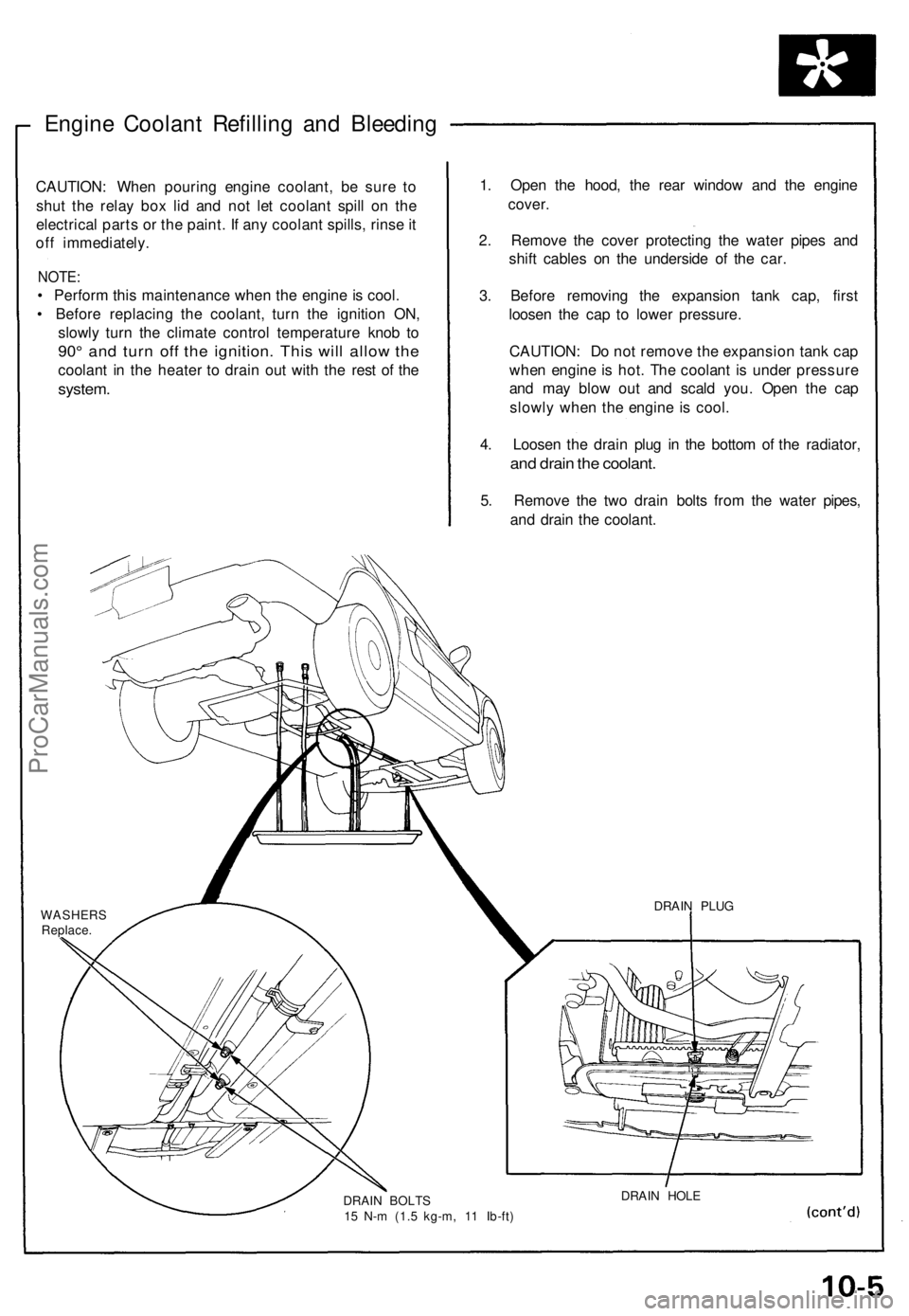
Engine Coolant Refilling and Bleeding
CAUTION: When pouring engine coolant, be sure to
shut the relay box lid and not let coolant spill on the
electrical parts or the paint. If any coolant spills, rinse it
off immediately.
NOTE:
• Perform this maintenance when the engine is cool.
• Before replacing the coolant, turn the ignition ON,
slowly turn the climate control temperature knob to
90° and turn off the ignition. This will allow the
coolant in the heater to drain out with the rest of the
system.
1. Open the hood, the rear window and the engine
cover.
2. Remove the cover protecting the water pipes and
shift cables on the underside of the car.
3. Before removing the expansion tank cap, first
loosen the cap to lower pressure.
CAUTION: Do not remove the expansion tank cap
when engine is hot. The coolant is under pressure
and may blow out and scald you. Open the cap
slowly when the engine is cool.
4. Loosen the drain plug in the bottom of the radiator,
and drain the coolant.
5. Remove the two drain bolts from the water pipes,
and drain the coolant.
WASHERS
Replace.
DRAIN BOLTS
15 N-m (1.5 kg-m, 11 Ib-ft)
DRAIN HOLE
DRAIN PLUGProCarManuals.com
Page 620 of 1640
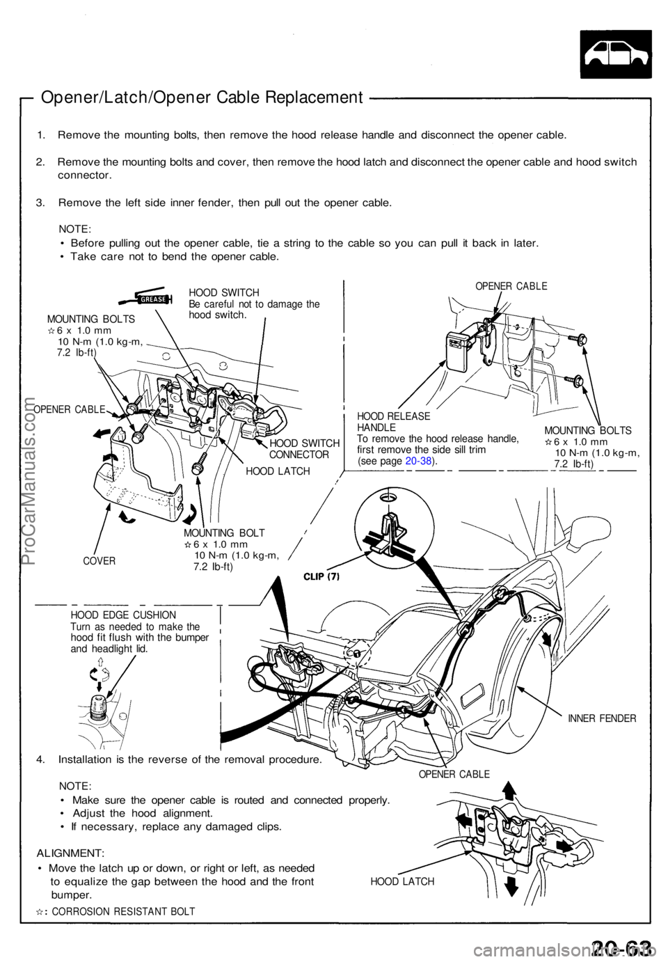
Opener/Latch/Opener Cabl e Replacemen t
1. Remov e th e mountin g bolts , the n remov e th e hoo d releas e handl e an d disconnec t th e opene r cable .
2 . Remov e th e mountin g bolt s an d cover , the n remov e th e hoo d latc h an d disconnec t th e opene r cabl e an d hoo d switc h
connector .
3 . Remov e th e lef t sid e inne r fender , the n pul l ou t th e opene r cable .
NOTE :
• Befor e pullin g ou t th e opene r cable , ti e a strin g t o th e cabl e s o yo u can pull i t bac k i n later .
• Tak e car e no t t o ben d th e opene r cable .
MOUNTIN G BOLT S6 x 1. 0 m m10 N- m (1. 0 kg-m ,7.2 Ib-ft )
OPENE R CABL E
HOOD SWITC HBe carefu l no t t o damag e th ehoo d switch .
OPENE R CABL E
HOOD SWITC HCONNECTO R
HOOD LATC H
HOOD RELEAS EHANDLETo remov e th e hoo d releas e handle ,first remov e th e sid e sil l tri m(se e pag e 20-38 ).
MOUNTIN G BOLT S6 x 1. 0 m m10 N- m (1. 0 kg-m ,7.2 Ib-ft )
COVE R
MOUNTIN G BOL T6 x 1. 0 m m10 N- m (1. 0 kg-m ,7.2 Ib-ft )
HOO D EDG E CUSHIO NTurn a s neede d t o mak e th ehoo d fi t flus h wit h th e bumpe rand headligh t lid .
4. Installatio n i s th e revers e of the remova l procedure .
NOTE:
• Mak e sur e th e opene r cabl e i s route d an d connecte d properly .
• Adjus t th e hoo d alignment .
• I f necessary , replac e an y damage d clips .
INNER FENDE R
OPENER CABL E
ALIGNMENT :
• Mov e th e latc h u p o r down , o r righ t o r left , a s neede d
t o equaliz e th e ga p betwee n th e hoo d an d th e fron t
bumper .
CORROSIO N RESISTAN T BOL T
HOOD LATC H
ProCarManuals.com
Page 860 of 1640
(G551) '95-'96 Models.
(G401,G402,G551) '93-94 Models or
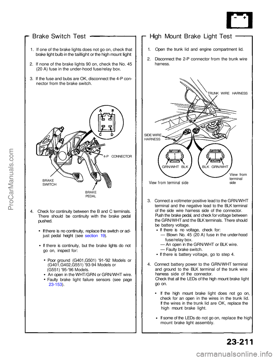
Brake Switch
Test
1
.
If one of the brake lights does not go on, check that
brake
light bulb in the taillight or the high mount light
2
.
If none of the brake lights 90 on, check the No. 45 (2
0
A) fuse in the under-hood fuse/relay box.
3
.
If the fuse and bubs are OK, disconnect the 4-P con- necto
r
from the brake switch.
4-P CONNECTOR
BRAKE
SWITCH
BRAKE
PEDAL
4. Check for continuity between the B and C terminals. There should be continuity with the brake pedal
pushed.
If there is no continuity, replace the switch or ad-
just pedal height (see section 19).
If there is continuity, but the brake lights do not
go on, inspect for:
Poor ground (G401,G501) '91-'92 Models or
An open in the WHT/GRN or GRN/WHT wire. Faulty brake light failure sensors (see page 23-153). High Mount Brake Light Test
1. Open the trunk lid and engine compartment lid.
2. Disconnect the 2-P connector from the trunk wire
harness.
TRUNK WIRE HARNESS
SIDE WIRE
HARNESS
View from terminal side
View from
terminal
side
3. Connect a voltmeter positive lead to the GRN/WHT terminal and the negative lead to the BLK terminalof the side wire harness side of the connector.
Push the brake pedal, and check for voltage between
the GRN/WHT and the BLK terminals. There should be battery voltage. If there is no voltage, check for:
— Blown No. 45 (20 A) fuse in the under-hood
fuse/relay box.
— An open in the GRN/WHT or BLK wire.
— Faulty brake switch.
If there is battery voltage, go to step 4.
4. Connect battery power to the GRN/WHT terminal and ground to the BLK terminal of the trunk wireharness side of the connector.
Check that all the LEDs of the high mount brake light
go on.
If the high mount brake light does not go on,check for an open in the wires
in the trunk lid.
If the wires in the trunk lid are OK, replace the
high mount brake light.
If some of the LEDs do not go on,
replace the high
mount brake light assembly.
GRN/WHT BLK
BLK GRN/WHTProCarManuals.com
Page 888 of 1640
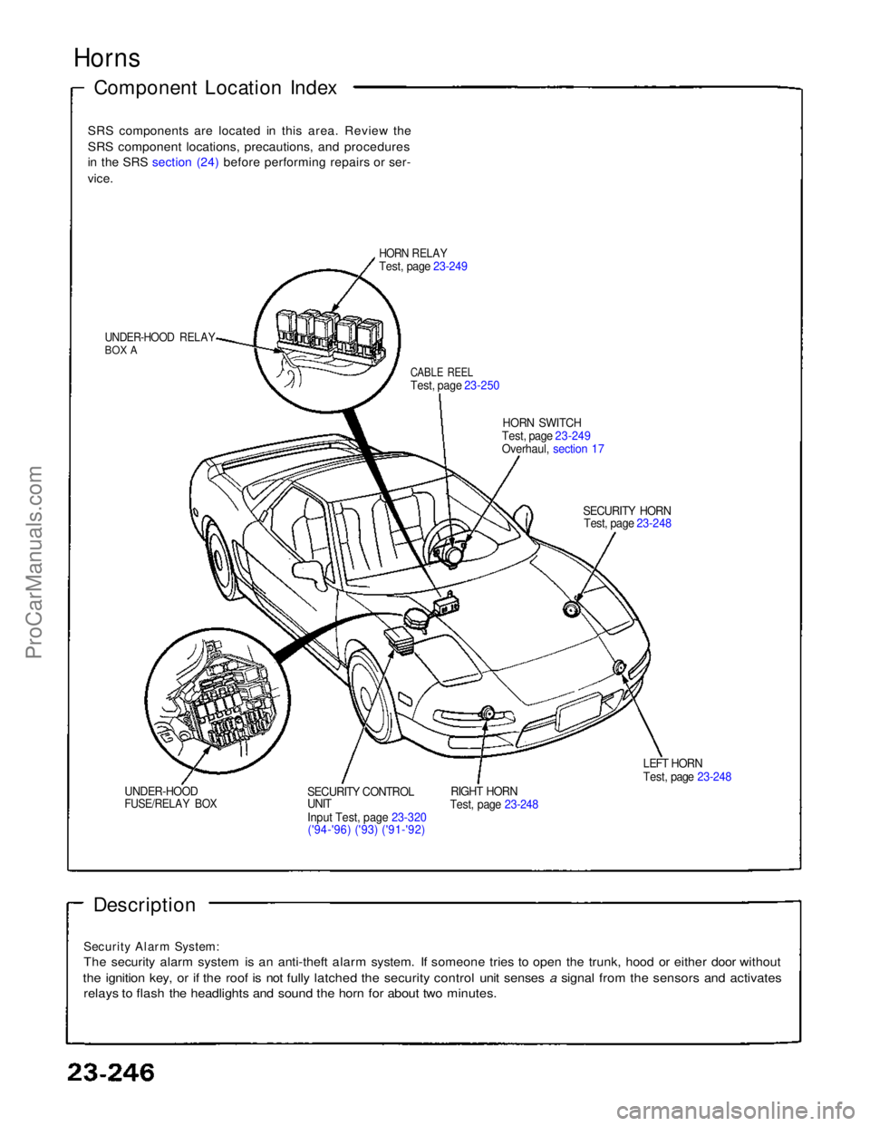
Horns
Component Location Index
SRS components are located in this area. Review the
SRS component locations, precautions, and procedures
in the SRS section (24) before performing repairs or ser-
vice.
HORN RELAY
Test, page 23-249
UNDER-HOOD RELAY
BOX A
CABLE REEL
Test, page 23-250
HORN SWITCH
Test, page 23-249
Overhaul, section 17
SECURITY HORNTest, page 23-248
LEFT HORN
Test, page 23-248
RIGHT HORN
Test, page 23-248
SECURITY CONTROL
UNIT
Inpu
t
Test, page 23-320
('94-'96) ('93) ('91-'92)
UNDER-HOOD
FUSE/RELAY BOX
Description
Security Alarm System:
The security alarm system is an anti-theft alarm system. If someone tries to open the trunk, hood or either door without
the ignition key, or if the roof is not fully latched the security control unit senses a signal from the sensors and activates
relays to flash the headlights and sound the horn for about two minutes.ProCarManuals.com
Page 908 of 1640
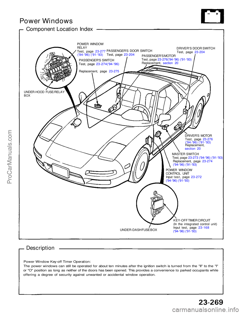
Power Windows
Component Location Index
POWER WINDOW
RELAY
Test
,
page 23-277
('94-'96) ('91-'93)
PASSENGER'S SWITCH
Test, page 23-274('94-'96)
Replacement, page
23-275
PASSENGER'S DOOR SWITCH
Test, page 23-204
PASSENGER'S MOTOR
Test, page 23-276('94-'96) ('91-'93)
Replacement, section 20
DRIVER'S DOOR SWITCH
Test, page 23-204
DRIVER'S MOTORTest, page 23-276('94-'96) ('91-'93)
Replacement,
section 20
MASTER SWITCH
Test, page 23-273 ('94-'96) ('91-'93)
Replacement, page 23-274
('94-'96) ('91-'93)
POWER WINDOW
CONTROL UNIT
Input test, page 23-272
('94-'96) ('91-'93)
KEY-OFF TIMER CIRCUIT
(In the integrated control unit)
Input test, page 23-168
('94-'96) ('91-'93)
UNDER-DASH FUSE BOX
UNDER-HOOD FUSE/RELAY
BOX
Description
Power Window Key-off Timer Operation:
The power windows can still be operated for about ten minutes after the ignition switch is turned from the "II" to the "I"
or "O" position as long as neither of the doors has been opened. This provides a convenience to parked occupants while
offering a degree of security against unwanted or accidental window operation.ProCarManuals.com
Page 929 of 1640
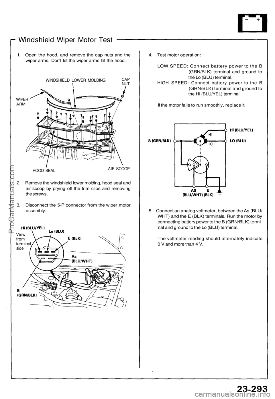
Windshield Wiper Motor Test
1. Open the hood, and remove the cap nuts and the
wiper arms. Don't let the wiper arms hit the hood.
WIPER
ARM
WINDSHIELD LOWER MOLDING
HOOD SEAL
AIR SCOOP
2. Remove the windshield lower molding, hood seal and
air scoop by prying off the trim clips and removing
the screws.
3. Disconnect the 5-P connector from the wiper motor
assembly.
View
from
terminal
side
4. Test motor operation:
LOW SPEED: Connect battery power to the B
(GRN/BLK) terminal and ground to
the Lo (BLU) terminal.
HIGH SPEED: Connect battery power to the B
(GRN/BLK) terminal and ground to
the Hi (BLU/YEL) terminal.
If the motor fails to run smoothly, replace it.
5. Connect an analog voltmeter, between the As (BLU/
WHT) and the E (BLK) terminals. Run the motor by
connecting battery power to the B (GRN/BLK) termi-
nal and ground to the Lo (BLU) terminal.
The voltmeter reading should alternately indicate
0 V and more than 4 V.
CAP
NUTProCarManuals.com
Page 930 of 1640
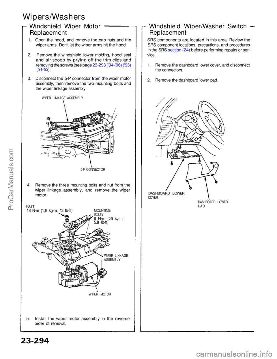
Wipers/Washers
Windshield Wiper MotorReplacement
1. Open the hood, and remove the cap nuts and the wiper arms. Don't let the wiper arms hit the hood.
2. Remove the windshield lower molding, hood seal
and air scoop by prying off the trim clips and
removing the screws (see page 23-293 ('94-'96) ('93)
('91-'92).
3. Disconnect the 5-P connector from the wiper motor assembly, then remove the two mounting bolts and
the wiper linkage assembly.
WIPER LINKAGE ASSEMBLY
5-P CONNECTOR
4. Remove the three mounting bolts and nut from the wiper linkage assembly, and remove the wiper
motor.
MOUNTING
BOLTS
8 N·m
(0.8 kg-m,
5.8 Ib-ft)
NUT
18 N·m (1,8 kg-m, 13 Ib-ft)
WIPER LINKAGE
ASSEMBLY
WIPER MOTOR
5. Install the wiper motor assembly in the reverse order of removal.
DASHBOARD LOWER
PAD
DASHBOARD LOWER
COVER
Windshield Wiper/Washer Switch
Replacement
SRS components are located in this area. Review the SRS component locations, precautions, and procedures
in the SRS section (24) before performing repairs or ser-
vice.
1. Remove the dashboard lower cover, and disconnect the connectors.
2. Remove the dashboard lower pad.ProCarManuals.com
Page 947 of 1640
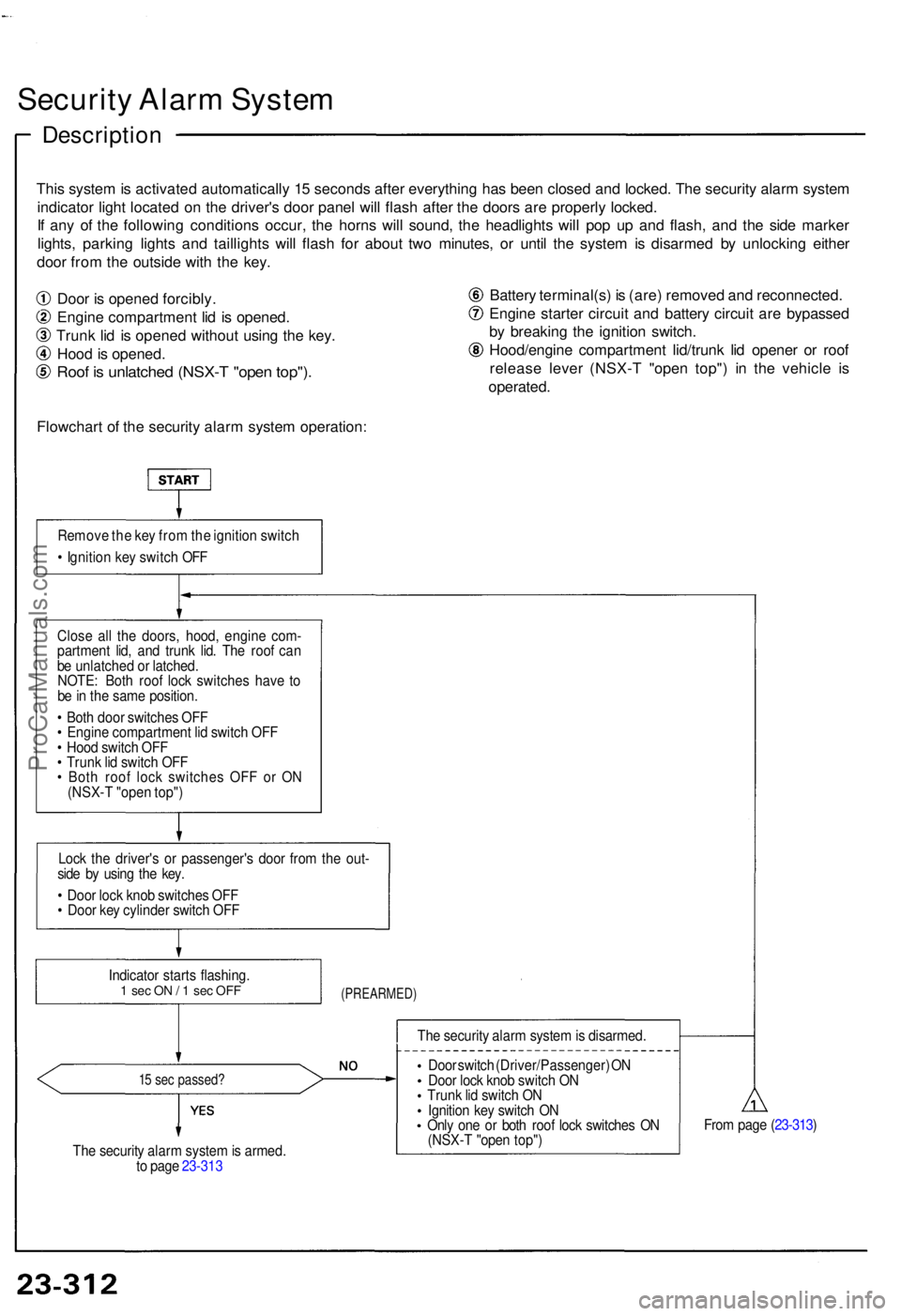
Security Alar m Syste m
Descriptio n
This syste m is activate d automaticall y 1 5 second s afte r everythin g ha s bee n close d an d locked . Th e securit y alar m syste m
indicato r ligh t locate d o n th e driver' s doo r pane l wil l flas h afte r th e door s ar e properl y locked .
I f an y o f th e followin g condition s occur , th e horn s wil l sound , th e headlight s wil l po p u p an d flash , an d th e sid e marke r
lights , parkin g light s an d taillight s wil l flas h fo r abou t tw o minutes , o r unti l th e syste m is disarme d b y unlockin g eithe r
doo r fro m th e outsid e wit h th e key .
Doo r i s opene d forcibly .
Engin e compartmen t li d i s opened .
Trun k li d i s opene d withou t usin g th e key .
Hoo d is opened .
Roof i s unlatche d (NSX- T "ope n top") .
Flowchar t o f th e securit y alar m syste m operation : Batter
y terminal(s ) i s (are ) remove d an d reconnected .
Engin e starte r circui t an d batter y circui t ar e bypasse d
b y breakin g th e ignitio n switch .
Hood/engin e compartmen t lid/trun k li d opene r o r roo f
releas e leve r (NSX- T "ope n top" ) i n th e vehicl e i s
operated .
Remove th e ke y fro m th e ignitio n switc h
• Ignitio n ke y switc h OF F
Clos e al l th e doors , hood , engin e com -
partmen t lid , an d trun k lid . Th e roo f ca n
b e unlatche d o r latched .
NOTE : Bot h roo f loc k switche s hav e t o
b e in th e sam e position .
• Bot h doo r switche s OF F
• Engin e compartmen t li d switc h OF F
• Hoo d switc h OF F
• Trun k li d switc h OF F
• Bot h roo f loc k switche s OF F o r O N
(NSX- T "ope n top" )
Loc k th e driver' s o r passenger' s doo r fro m th e out -
sid e b y usin g th e key .
• Doo r loc k kno b switche s OF F
• Doo r ke y cylinde r switc h OF F
(PREARMED )
15 se c passed ?
The securit y alar m syste m is armed .
t o pag e 23-31 3 Th
e securit y alar m syste m is disarmed .
Doo r switc h (Driver/Passenger ) O N
Doo r loc k kno b switc h O N
Trun k li d switc h O N
Ignitio n ke y switc h O N
Onl y on e o r bot h roo f loc k switche s O N
(NSX- T "ope n top" ) Fro
m pag e ( 23-313 )
Indicato
r start s flashing .
1 se c O N / 1 se c OF F
ProCarManuals.com
Page 948 of 1640
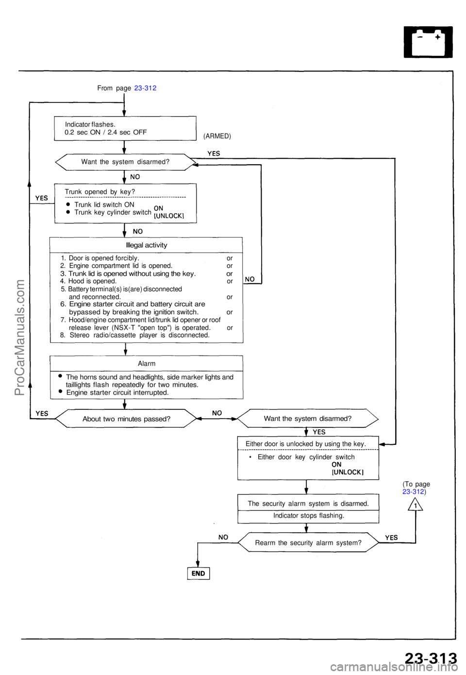
From pag e 23-31 2
Indicato r flashes .
0.2 se c O N / 2. 4 se c OF F
Wan t th e syste m disarmed ?
(ARMED)
Trunk opene d b y key ?
Trun k li d switc h O N
Trun k ke y cylinde r switc h
Illegal activit y
1. Doo r i s opene d forcibly . o r
2 . Engin e compartmen t li d i s opened . o r
3. Trun k li d is opene d withou t usin g th e key . o r4. Hoo d is opened . o r
5 . Batter y terminal(s ) is(are ) disconnecte d
an d reconnected . o r
6. Engin e starte r circui t an d batter y circui t ar ebypasse d b y breakin g th e ignitio n switch . o r7. Hood/engin e compartmen t lid/trun k li d opene r o r roo f
releas e leve r (NSX- T "ope n top" ) i s operated . o r
8 . Stere o radio/cassett e playe r i s disconnected .
Alar m
The horn s soun d an d headlights , sid e marke r light s an dtaillight s flas h repeatedl y fo r tw o minutes .Engine starte r circui t interrupted .
About tw o minute s passed ?Want th e syste m disarmed ?
Either doo r i s unlocke d b y usin g th e key .
• Eithe r doo r ke y cylinde r switc h
Th e securit y alar m syste m is disarmed .
Indicato r stop s flashing . (T
o pag e
23-312 )
Rear m th e securit y alar m system ?
ProCarManuals.com
Page 956 of 1640
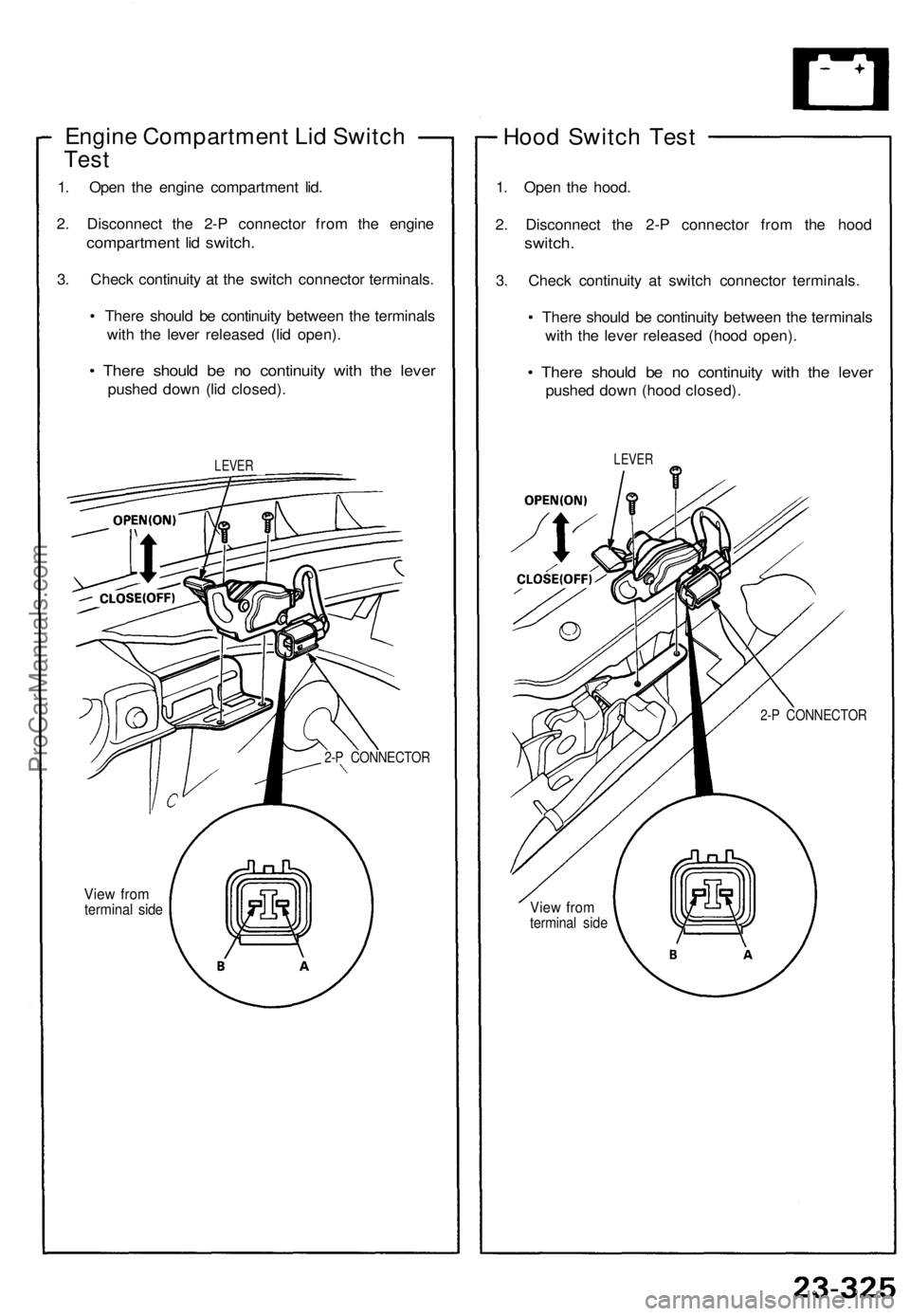
Engine Compartment Lid Switch
Test
1. Open the engine compartment lid.
2. Disconnect the 2-P connector from the engine
compartment lid switch.
3. Check continuity at the switch connector terminals.
• There should be continuity between the terminals
with the lever released (lid open).
• There should be no continuity with the lever
pushed down (lid closed).
LEVER
View from
terminal side
2-P CONNECTOR
Hood Switch Test
1. Open the hood.
2. Disconnect the 2-P connector from the hood
switch.
3. Check continuity at switch connector terminals.
• There should be continuity between the terminals
with the lever released (hood open).
• There should be no continuity with the lever
pushed down (hood closed).
LEVER
2-P CONNECTOR
View from
terminal sideProCarManuals.com