weight ACURA NSX 1991 Service Repair Manual
[x] Cancel search | Manufacturer: ACURA, Model Year: 1991, Model line: NSX, Model: ACURA NSX 1991Pages: 1640, PDF Size: 60.48 MB
Page 11 of 1640
Towing
If th e ca r need s t o b e towed , cal l a professiona l towin g
service . Neve r to w th e ca r behin d anothe r ca r wit h jus t
a rop e o r chain . I t i s ver y dangerous .
Ther e ar e thre e widel y use d method s o f towin g a car :
Flat-be d Equipmen t — Th e operato r load s th e ca r o n th e
bac k o f a truck . Thi s i s th e onl y recommende d wa y o f
towin g th e NS X & NSX-T .
Whee l Lif t Equipment— The to w truc k drive r use s tw o
pivotin g arm s whic h g o unde r th e tire s (fron t o r rear ) an d
lif t the m of f th e ground . Th e othe r tw o wheel s remai n
o n th e ground . Thi s towin g metho d i s no t recommend -
ed . Becaus e o f th e NS X & NSX-T' s lo w groun d clearance ,
th e bod y ca n b e damage d goin g ove r larg e bump s o r u p
inclines .
Sling-typ e Equipment— The tow truc k use s meta l chain s
wit h hook s o n th e ends . Thes e hook s g o aroun d part s
of th e fram e or suspensio n and th e cable s lift tha t end
of th e ca r of f th e ground . Damag e t o th e car' s suspen -
sio n an d bod y i s almos t certai n if thi s metho d o f towin g
i s attempted .
I f th e NS X & NSX- T canno t b e towe d b y flat-bed , i t
shoul d b e towe d wit h th e rea r wheel s of f th e ground .
If , du e t o damage , th e ca r mus t b e towe d wit h th e rea r
wheel s o n th e ground , d o th e following :
Manual Transmissio n
• Releas e th e parkin g brak e
• Shif t th e transmissio n t o Neutra l
Automati c Transmissio n
• Releas e th e parkin g brak e
• Star t th e engin e
• Shif t t o position , the n t o positio n
• Tur n of f th e engin e
NOTICE :
• Imprope r towin g preparatio n wil l damag e th e trans -
mission . Follo w th e abov e procedur e exactly . Th e ca r
mus t b e towe d o n a fla t be d if th e engin e wil l no t star t
o r th e transmissio n wil l no t shift .
• I t i s bes t t o to w th e ca r n o farthe r tha n 5 0 mile s (8 0
km) , an d kee p th e spee d belo w 3 5 mp h (5 5 km/h) .
• Tryin g t o lif t o r to w th e ca r b y th e bumper s wil l caus e
seriou s damage . Th e bumper s ar e no t designe d to sup -
por t th e car' s weight .
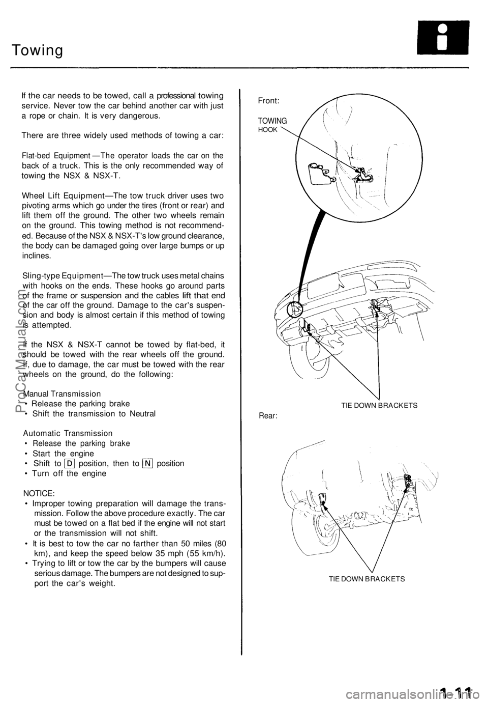
Front:
TOWIN GHOOK
TIE DOW N BRACKET S
Rear:
TIE DOW N BRACKET S
ProCarManuals.com
Page 44 of 1640
Towing
If th e ca r need s t o b e towed , cal l a professiona l towin g
service . Neve r to w th e ca r behin d anothe r ca r wit h jus t
a rop e o r chain . I t i s ver y dangerous .
Ther e ar e thre e widel y use d method s o f towin g a car :
Flat-be d Equipment—Th e operato r load s th e ca r o n th e
bac k o f a truck . This is th e onl y recommende d wa y o f
towin g th e NS X & NSX-T .
Whee l Lif t Equipment—Th e to w truc k drive r use s tw o
pivotin g arm s whic h g o unde r th e tire s (fron t o r rear ) an d
lif t the m of f th e ground . Th e othe r tw o wheel s remai n
o n th e ground . Thi s towin g metho d i s no t recommend -
ed . Becaus e o f th e NS X & NSX-T' s lo w groun d clearance ,
th e bod y ca n b e damage d goin g ove r larg e bump s o r u p
inclines .
Sling-typ e Equipment—Th e to w truc k use s meta l chain s
wit h hooks on th e ends . Thes e hook s g o aroun d part s
o f th e fram e o r suspensio n an d th e cable s lif t tha t en d
o f th e ca r of f th e ground . Damag e t o th e car' s suspen -
sio n an d bod y i s almos t certai n if thi s metho d o f towin g
i s attempted .
I f th e NS X & NSX- T canno t b e towe d b y flat-bed , i t
shoul d b e towe d wit h th e rea r wheel s of f th e ground .
If , du e t o damage , th e ca r mus t b e towe d wit h th e rea r
wheel s o n th e ground , d o th e following :
Manual Transmissio n
Release th e parkin g brak e
Shift th e transmissio n t o Neutra l
Automati c Transmissio n
Releas e th e parkin g brak e
Star t th e engin e
Shift t o position , the n t o positio n
Tur n of f th e engin e
NOTICE :
Improper towin g preparatio n wil l damag e th e trans -
mission . Follo w th e abov e procedur e exactly . Th e ca r
mus t b e towe d o n a fla t be d if th e engin e wil l no t star t
or th e transmissio n wil l no t shift .
It i s bes t t o to w th e ca r n o farthe r tha n 5 0 mile s (8 0
km) , an d kee p th e spee d belo w 3 5 mp h (5 5 km/h) .
Tryin g t o lif t o r to w th e ca r b y th e bumper s wil l caus e
seriou s damage . Th e bumper s ar e no t designe d to sup -
por t th e car' s weight .
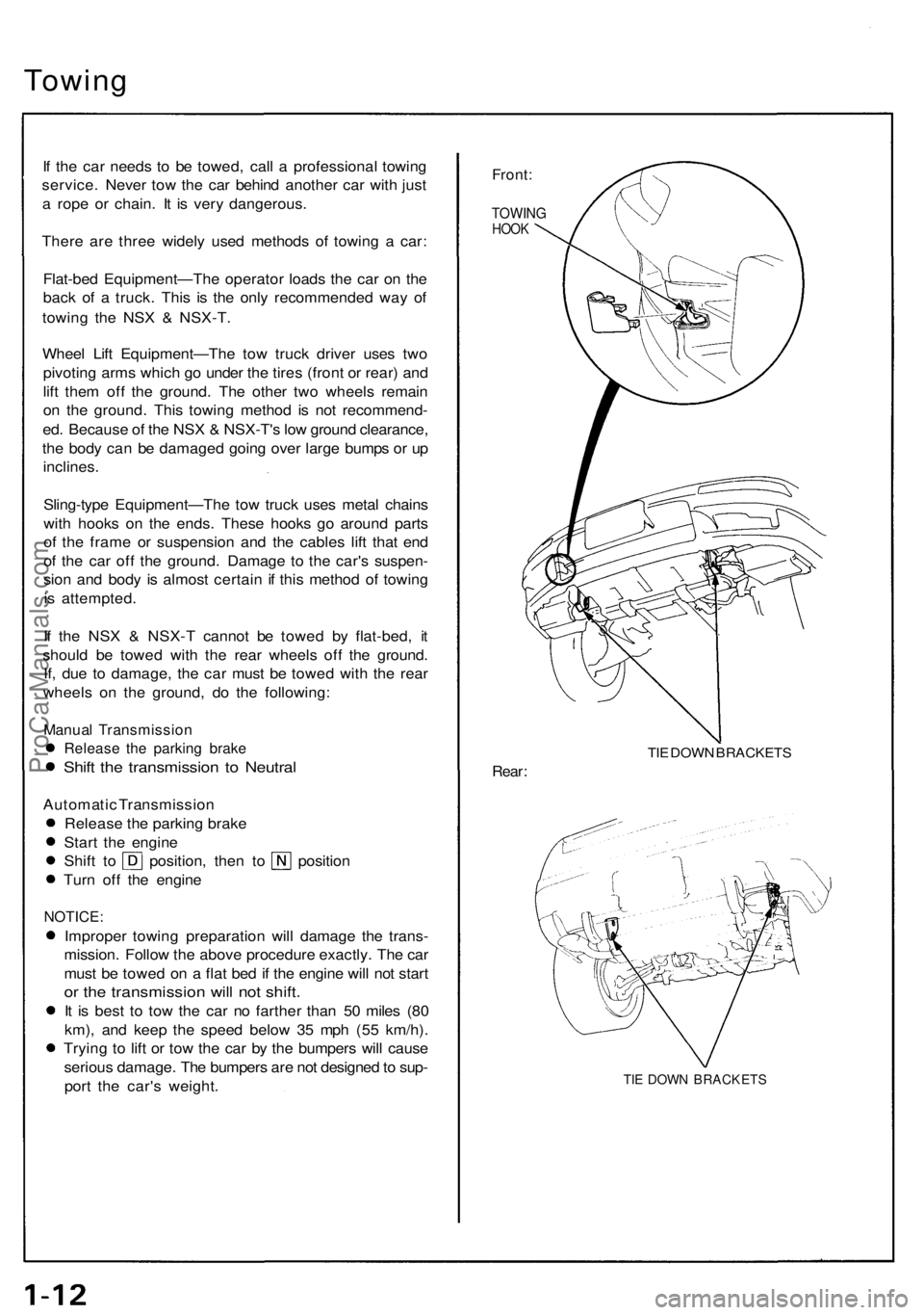
Front:
TOWIN GHOOK
TIE DOW N BRACKET S
Rear:
TIE DOW N BRACKET S
ProCarManuals.com
Page 131 of 1640
Main Bearing s
Clearanc e
1. T o chec k mai n bearing-to-journa l oi l clearance ,
remov e th e mai n cap s an d bearin g halves .
2 . Clea n eac h mai n journa l an d bearin g hal f wit h a
clea n sho p towel.
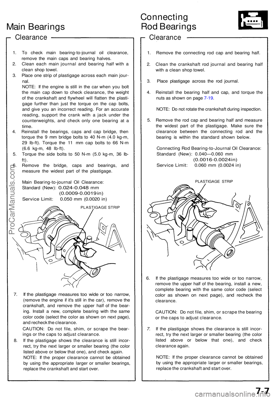
3 . Plac e on e stri p o f plastigag e acros s eac h mai n jour -
nal.
NOTE : I f th e engine is stil l i n th e ca r whe n yo u bol t
th e mai n ca p dow n t o chec k clearance , th e weigh t
o f th e crankshaf t an d flywhee l wil l flatte n th e plasti -
gag e furthe r tha n jus t th e torqu e o n th e ca p bolts ,
an d giv e yo u a n incorrec t reading . Fo r a n accurat e
reading , suppor t th e cran k wit h a jac k unde r th e
counterweights , an d chec k onl y on e bearin g a t a
time .
4. Reinstal l th e bearings , cap s an d ca p bridge , the n
torqu e th e 9 m m bridg e bolt s t o 4 0 N- m (4. 0 kg-m ,
2 9 Ib-ft) . Torqu e th e 1 1 m m ca p bolt s t o 6 6 N- m
(6. 6 kg-m , 4 8 Ib-ft) .
5 . Torqu e th e sid e bolt s t o 5 0 N- m (5. 0 kg-m , 3 6 Ib -
ft).
6. Remov e th e bridge , cap s an d bearings , an d
measur e th e wides t par t o f th e plastigage .
Mai n Bearing-to-journa l Oi l Clearance :
Standar d
(New): 0.024-0.04 8 mm
(0.0009-0.001 9 in )
Servic e Limit : 0.05 0 m m (0.002 0 in )
PLASTIGAG E STRI P
7. I f th e plastigag e measure s to o wid e o r to o narrow ,
(remove th e engine if it' s stil l i n th e car) , remov e th e
crankshaft , an d remov e th e uppe r hal f o f th e bear -
ing . Instal l a new , complet e bearin g wit h th e sam e
colo r cod e (selec t th e colo r a s show n o n nex t page) ,
an d rechec k th e clearance .
CAUTION : D o no t file , shim , o r scrap e th e bear -
ing s o r th e cap s t o adjus t clearance .
8 . I f th e plastigag e show s th e clearanc e i s stil l incor -
rect , tr y th e nex t large r o r smalle r bearin g (th e colo r
liste d abov e o r belo w tha t one) , an d chec k again .
NOTE : I f th e prope r clearanc e canno t b e obtaine d
b y usin g th e appropriat e large r o r smalle r bearings ,
replac e th e crankshaf t an d star t over .
Connectin g
Rod Bearing s
Clearanc e
1. Remov e th e connectin g ro d ca p an d bearin g half .
2 . Clea n th e crankshaf t ro d journa l an d bearin g hal f
wit h a clea n sho p towel .
3 . Plac e plastigag e acros s th e ro d journal .
4 . Reinstal l th e bearin g hal f an d cap , an d torqu e th e
nut s a s show n o n pag e 7-19 .
NOTE : D o no t rotat e th e crankshaft during inspection .
5 . Remov e th e ro d ca p an d bearin g hal f an d measur e
th e wides t par t o f th e plastigage . Mak e sur e th e
clearanc e betwee n th e connectin g ro d an d th e
bearin g i s withi n th e standar d show n below .
Connectin g Ro d Bearing-to-Journa l Oi l Clearance :
Standar d (New) : 0.040—0.06 0 m m
(0.0016-0.002 4 in )
Servic e Limit : 0.06 0 m m (0.002 4 in )
PLASTIGAG E STRI P
6. I f th e plastigag e measure s to o wid e o r to o narrow ,
remov e th e uppe r hal f of the bearing , instal l a new ,
complet e bearin g wit h th e sam e colo r cod e (selec t
color a s show n o n nex t page) , an d rechec k th e
clearance .
CAUTION: D o no t file , shim , o r scrap e th e bearin g
o r th e cap s t o adjus t clearance .
7. I f th e plastigag e show s th e clearanc e i s stil l incor -
rect , tr y th e nex t large r o r smalle r bearin g (th e colo r
liste d abov e o r belo w tha t one) , an d chec k
clearanc e again .
NOTE : I f th e prope r clearanc e canno t b e obtaine d
b y usin g th e appropriat e large r o r smalle r bearings ,
replac e th e crankshaf t an d star t over .
ProCarManuals.com
Page 307 of 1640
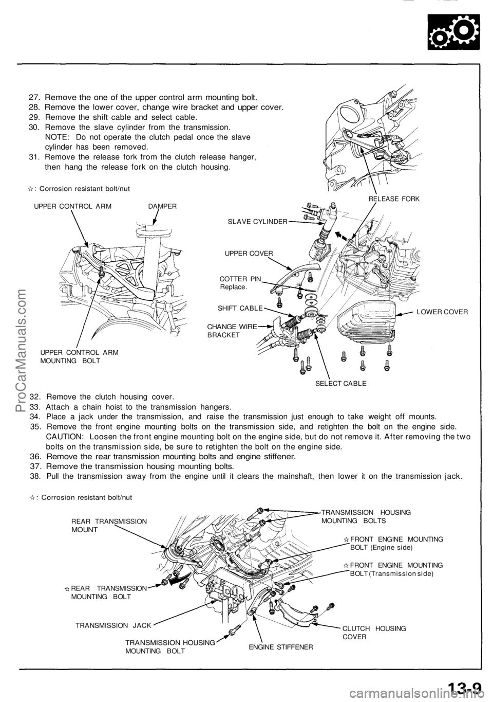
27. Remove the one of the upper control arm mounting bolt.
28. Remove the lower cover, change wire bracket and upper cover.
29. Remove the shift cable and select cable.
30. Remove the slave cylinder from the transmission.
NOTE: Do not operate the clutch pedal once the slave
cylinder has been removed.
31. Remove the release fork from the clutch release hanger,
then hang the release fork on the clutch housing.
Corrosion resistant bolt/nut
UPPER CONTROL ARM DAMPER
SLAVE CYLINDER
UPPER COVER
COTTER PIN
Replace.
SHIFT CABLE
CHANGE WIRE
BRACKET
UPPER CONTROL ARM
MOUNTING BOLT
LOWER COVER
SELECT CABLE
32. Remove the clutch housing cover.
33. Attach a chain hoist to the transmission hangers.
34. Place a jack under the transmission, and raise the transmission just enough to take weight off mounts.
35. Remove the front engine mounting bolts on the transmission side, and retighten the bolt on the engine side.
CAUTION: Loosen the front engine mounting bolt on the engine side, but do not remove it. After removing the two
bolts on the transmission side, be sure to retighten the bolt on the engine side.
36. Remove the rear transmission mounting bolts and engine stiffener.
37. Remove the transmission housing mounting bolts.
38. Pull the transmission away from the engine until it clears the mainshaft, then lower it on the transmission jack.
Corrosion resistant bolt/nut
REAR TRANSMISSION
MOUNT
REAR TRANSMISSION
MOUNTING BOLT
TRANSMISSION JACK
TRANSMISSION HOUSING
MOUNTING BOLTS
FRONT ENGINE MOUNTING
BOLT (Engine side)
FRONT ENGINE MOUNTING
BOLT (Transmission side)
TRANSMISSION HOUSING
MOUNTING BOLT
CLUTCH HOUSING
COVER
ENGINE STIFFENER
RELEASE FORKProCarManuals.com
Page 407 of 1640
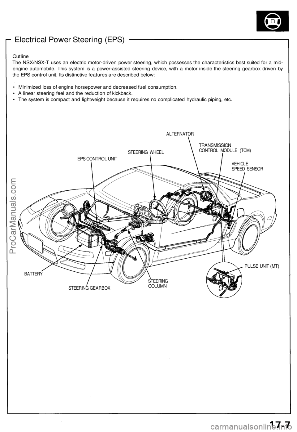
Electrical Power Steering (EPS)
Outline
The NSX/NSX-T uses an electric motor-driven power steering, which possesses the characteristics best suited for a mid-
engine automobile. This system is a power-assisted steering device, with a motor inside the steering gearbox driven by
the EPS control unit. Its distinctive features are described below:
• Minimized loss of engine horsepower and decreased fuel consumption.
• A linear steering feel and the reduction of kickback.
• The system is compact and lightweight because it requires no complicated hydraulic piping, etc.
ALTERNATOR
TRANSMISSION
CONTROL MODULE (TCM)
EPS CONTROL UNIT
VEHICLE
SPEED SENSOR
PULSE UNIT (MT)
BATTERY
STEERING GEARBOX
STEERING WHEEL
STEERING
COLUMNProCarManuals.com
Page 449 of 1640
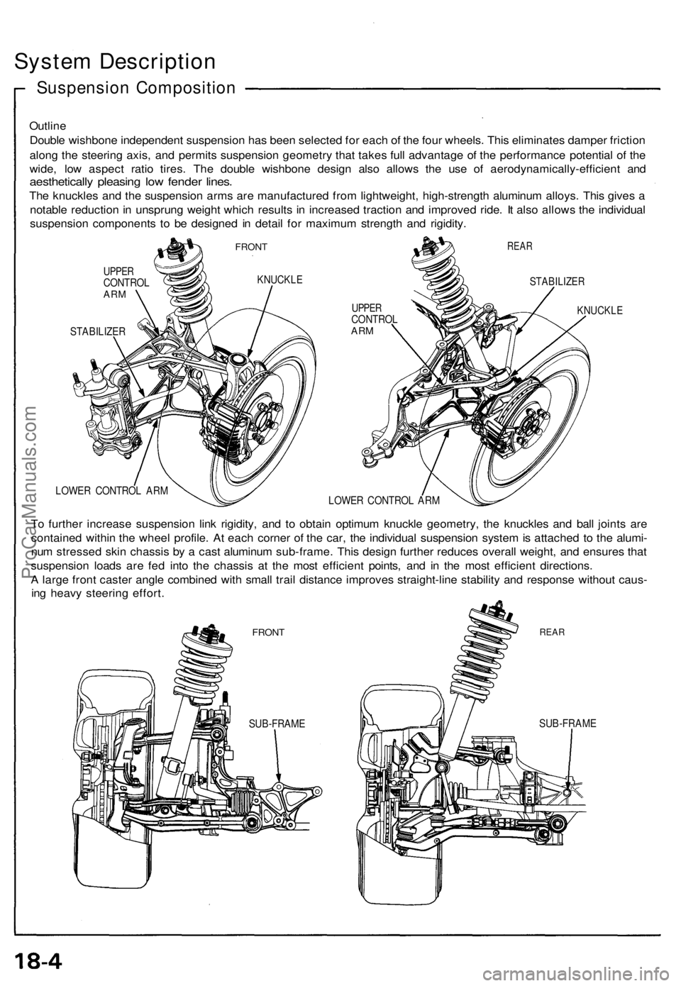
System Description
Suspension Composition
Outline
Double wishbone independent suspension has been selected for each of the four wheels. This eliminates damper friction
along the steering axis, and permits suspension geometry that takes full advantage of the performance potential of the
wide, low aspect ratio tires. The double wishbone design also allows the use of aerodynamically-efficient and
aesthetically pleasing low fender lines.
The knuckles and the suspension arms are manufactured from lightweight, high-strength aluminum alloys. This gives a
notable reduction in unsprung weight which results in increased traction and improved ride. It also allows the individual
suspension components to be designed in detail for maximum strength and rigidity.
FRONT
UPPER
CONTROL
ARM
KNUCKLE
STABILIZER
REAR
UPPER
CONTROL
ARM
STABILIZER
KNUCKLE
LOWER CONTROL ARM
LOWER CONTROL ARM
To further increase suspension link rigidity, and to obtain optimum knuckle geometry, the knuckles and ball joints are
contained within the wheel profile. At each corner of the car, the individual suspension system is attached to the alumi-
num stressed skin chassis by a cast aluminum sub-frame. This design further reduces overall weight, and ensures that
suspension loads are fed into the chassis at the most efficient points, and in the most efficient directions.
A large front caster angle combined with small trail distance improves straight-line stability and response without caus-
ing heavy steering effort.
FRONT
REAR
SUB-FRAME
SUB-FRAMEProCarManuals.com
Page 460 of 1640
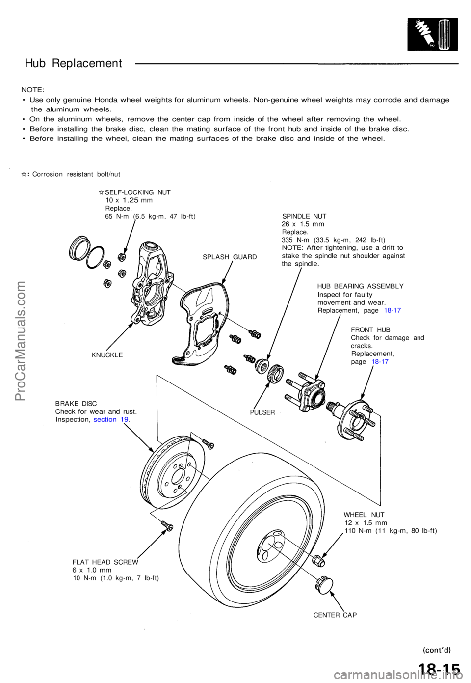
Hub Replacemen t
NOTE:
• Us e onl y genuin e Hond a whee l weight s fo r aluminu m wheels . Non-genuin e whee l weight s ma y corrod e an d damag e
th e aluminu m wheels .
• O n th e aluminu m wheels , remov e th e cente r ca p fro m insid e o f th e whee l afte r removin g th e wheel .
• Befor e installin g th e brak e disc , clea n th e matin g surfac e o f th e fron t hu b an d insid e o f th e brak e disc .
• Befor e installin g th e wheel , clea n th e matin g surface s of the brak e dis c an d insid e o f th e wheel .
Corrosio n resistan t bolt/nu t
SELF-LOCKIN G NU T
10 x 1.2 5 mmReplace .
6 5 N- m (6. 5 kg-m , 4 7 Ib-ft ) SPINDL E NU T
26 x 1. 5 m mReplace .
33 5 N- m (33. 5 kg-m , 24 2 Ib-ft )
NOTE : Afte r tightening , us e a drif t t ostak e th e spindl e nu t shoulde r agains tthe spindle .
HUB BEARIN G ASSEMBL YInspect fo r fault ymovemen t an d wear .Replacement , pag e 18-1 7
BRAK E DIS C
Chec k fo r wea r an d rust .Inspection , sectio n 19 .
FRON T HU B
Chec k fo r damag e an d
cracks .
Replacement ,page 18-1 7
WHEE L NU T
12 x 1. 5 m m110 N- m (1 1 kg-m , 8 0 Ib-ft )
FLAT HEA D SCRE W6 x 1. 0 m m10 N- m (1. 0 kg-m , 7 Ib-ft )
CENTER CA P
KNUCKL
E
PULSER
SPLAS H GUAR D
ProCarManuals.com
Page 476 of 1640
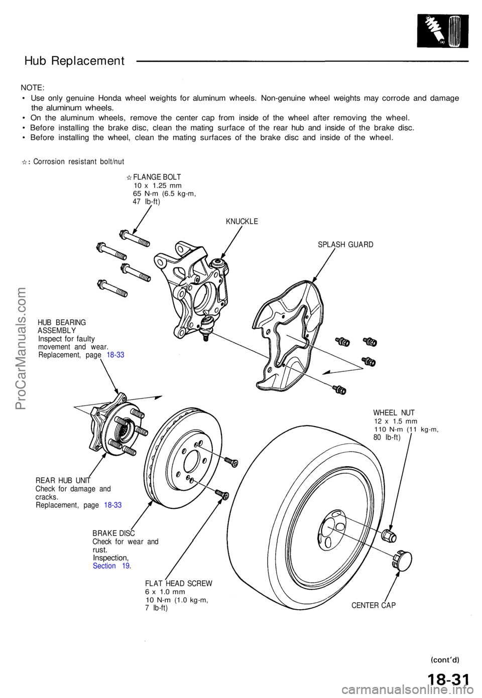
Hub Replacemen t
NOTE:
• Us e onl y genuin e Hond a whee l weight s fo r aluminu m wheels . Non-genuin e whee l weight s ma y corrod e an d damag e
the aluminu m wheels .
• O n th e aluminu m wheels , remov e th e cente r cap from insid e o f th e whee l afte r removin g th e wheel .
• Befor e installin g th e brak e disc , clea n th e matin g surfac e o f th e rea r hu b an d insid e o f th e brak e disc .
• Befor e installin g th e wheel , clea n th e matin g surface s o f th e brak e dis c an d insid e o f th e wheel .
Corrosio n resistan t bolt/nu t
FLANG E BOL T
10 x 1.2 5 mm65 N- m (6. 5 kg-m ,47 Ib-ft )
KNUCKL E
SPLASH GUAR D
HU B BEARIN G
ASSEMBL YInspect fo r fault ymovemen t an d wear .
Replacement , pag e 18-3 3
WHEEL NU T
12 x 1. 5 m m110 N- m (1 1 kg-m ,80 Ib-ft )
REA R HU B UNI T
Chec k fo r damag e an d
cracks .
Replacement , pag e 18-3 3
BRAK E DIS C
Chec k fo r wea r an d
rust .Inspection ,Section 19 .
FLAT HEA D SCRE W
6 x 1. 0 m m10 N- m (1. 0 kg-m ,7 Ib-ft ) CENTE
R CA P
ProCarManuals.com
Page 966 of 1640
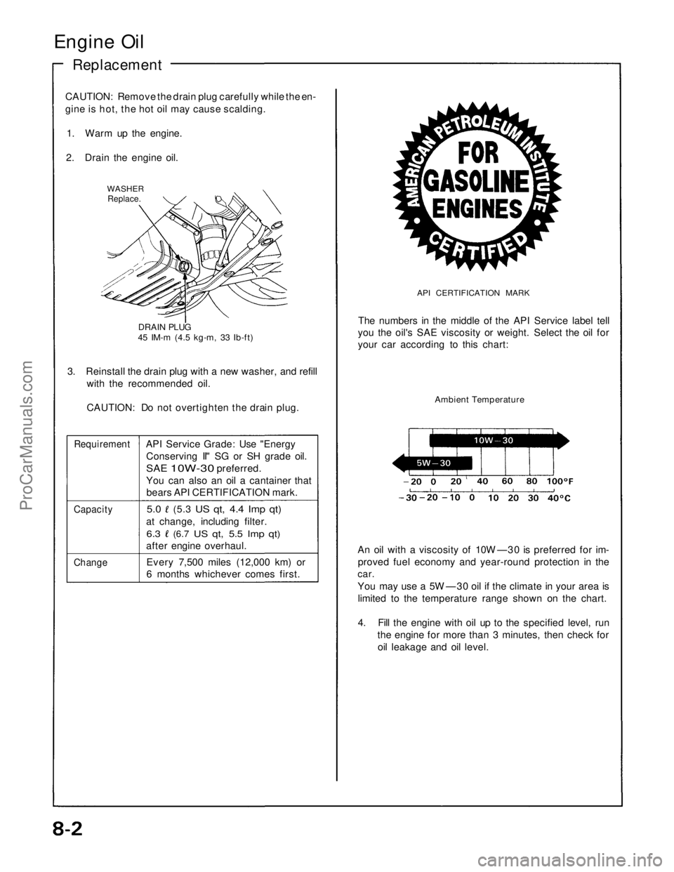
Engine Oil
Replacement
CAUTION: Remove the drain plug carefully while the en-
gine is hot, the hot oil may cause scalding.
1. Warm up the engine.
2. Drain the engine oil.
WASHER
Replace.
DRAIN PLUG
45 IM-m (4.5 kg-m, 33 Ib-ft)
3. Reinstall the drain plug with a new washer, and refill
with the recommended oil.
CAUTION: Do not overtighten the drain plug.
Requirement
API Service Grade: Use "Energy
Conserving II" SG or SH grade oil.
SAE
10W-30
preferred.
You can also an oil a cantainer that
bears API CERTIFICATION mark.
Capacity
5.0
(5.3
US qt, 4.4 Imp qt)
at change, including filter.
6.3
(6.7
US qt, 5.5 Imp qt)
after engine overhaul.
Change
Every 7,500 miles (12,000 km) or
6 months whichever comes first.
API CERTIFICATION MARK
The numbers in the middle of the API Service label tell
you the oil's SAE viscosity or weight. Select the oil for
your car according to this chart:
Ambient Temperature
An oil with a viscosity of 10W —30 is preferred for im-
proved fuel economy and year-round protection in the
car.
You may use a 5W —30 oil if the climate in your area is
limited to the temperature range shown on the chart.
4. Fill the engine with oil up to the specified level, run
the engine for more than 3 minutes, then check for
oil leakage and oil level.ProCarManuals.com
Page 978 of 1640
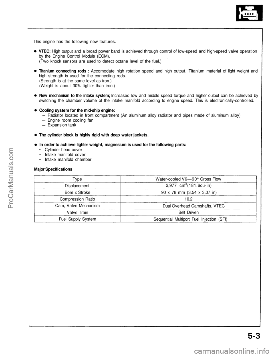
This engine has the following new features.
Type
Displacement
Bore x Stroke
Compression Ratio
Cam, Valve Mechanism
Valve Train
Fuel Supply System Water-cooled V6—90° Cross Flow
2,977 cm3(181.6cu-in)
90 x 78 mm
(3.54
x
3.07
in)
10.2
Dual Overhead Camshafts, VTEC Belt Driven
Sequential Multiport Fuel Injection (SFI)VTEC; High output and a broad power band is achieved through control of low-speed and high-speed valve operation
by the Engine Control Module (ECM).
(Two knock sensors are used to detect octane level of the fuel.)
Titanium connecting rods ; Accomodate high rotation speed and high output. Titanium material of light weight and
high strength is used for the connecting rods.
(Strength is at the same level as iron.)
(Weight is about 30% lighter than iron.)
New mechanism to the intake system; Increased low and middle speed torque and higher output can be achieved by
switching the chamber volume of the intake manifold according to engine speed. This is electronically-controlled.
Cooling system for the mid-ship engine:
Radiator located in front compartment (An aluminum alloy radiator and pipes made of aluminum alloy)
Engine room cooling fan
Expansion tank
The cylinder block is highly rigid with deep water jackets. In order to achieve lighter weight, magnesium is used for the following parts: Cylinder head coverIntake manifold cover
Intake manifold chamber
Major SpecificationsProCarManuals.com