ACURA NSX 1997 Service Service Manual
NSX 1997
ACURA
ACURA
https://www.carmanualsonline.info/img/32/56989/w960_56989-0.png
ACURA NSX 1997 Service Service Manual
Page 721 of 1503
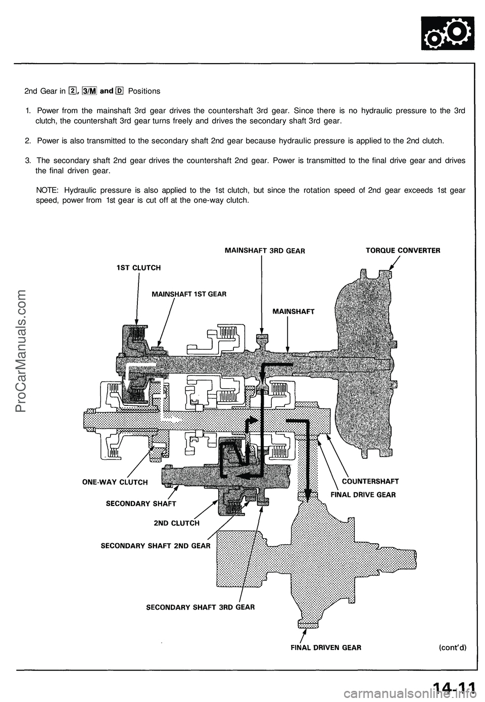
2nd Gear in Positions
1. Power from the mainshaft 3rd gear drives the countershaft 3rd gear. Since there is no hydraulic pressure to the 3rd
clutch, the countershaft 3rd gear turns freely and drives the secondary shaft 3rd gear.
2. Power is also transmitted to the secondary shaft 2nd gear because hydraulic pressure is applied to the 2nd clutch.
3. The secondary shaft 2nd gear drives the countershaft 2nd gear. Power is transmitted to the final drive gear and drives
the final driven gear.
NOTE: Hydraulic pressure is also applied to the 1st clutch, but since the rotation speed of 2nd gear exceeds 1st gear
speed, power from 1st gear is cut off at the one-way clutch.ProCarManuals.com
Page 722 of 1503
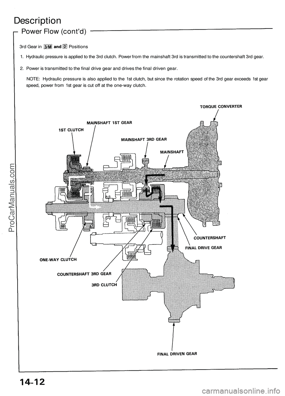
Description
Power Flow (cont'd)
3rd Gear in Positions
1. Hydraulic pressure is applied to the 3rd clutch. Power from the mainshaft 3rd is transmitted to the countershaft 3rd gear.
2. Power is transmitted to the final drive gear and drives the final driven gear.
NOTE: Hydraulic pressure is also applied to the 1st clutch, but since the rotation speed of the 3rd gear exceeds 1st gear
speed, power from 1st gear is cut off at the one-way clutch.ProCarManuals.com
Page 723 of 1503
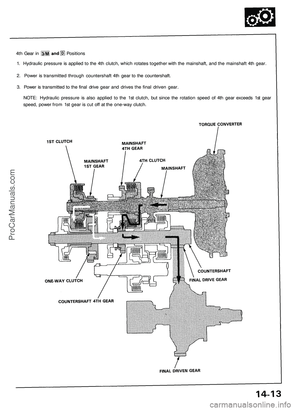
4th Gear in Positions
1. Hydraulic pressure is applied to the 4th clutch, which rotates together with the mainshaft, and the mainshaft 4th gear.
2. Power is transmitted through countershaft 4th gear to the countershaft.
3. Power is transmitted to the final drive gear and drives the final driven gear.
NOTE: Hydraulic pressure is also applied to the 1st clutch, but since the rotation speed of 4th gear exceeds 1st gear
speed, power from 1st gear is cut off at the one-way clutch.ProCarManuals.com
Page 727 of 1503
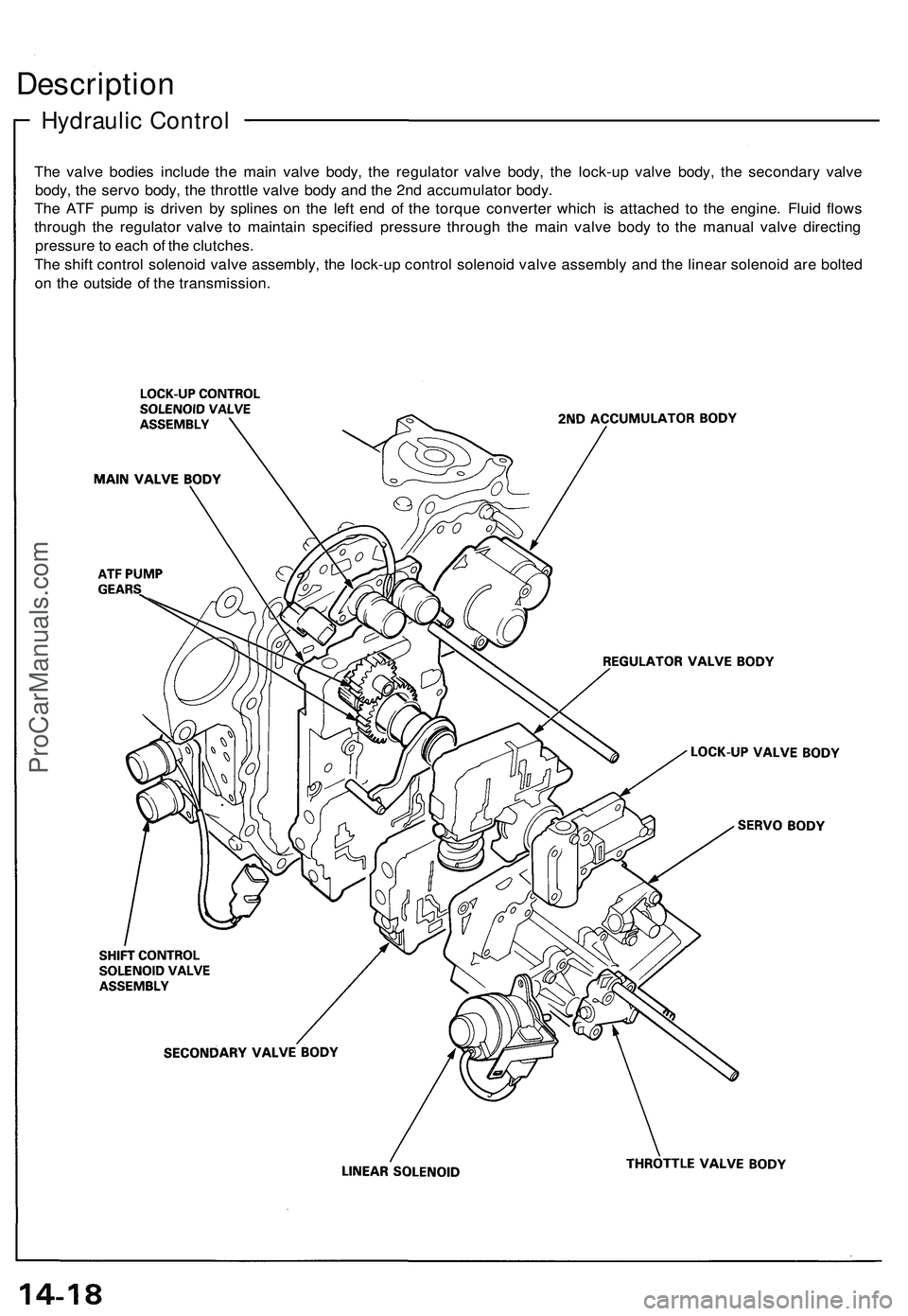
Hydraulic Control
Description
The valve bodies include the main valve body, the regulator valve body, the lock-up valve body, the secondary valve
body, the servo body, the throttle valve body and the 2nd accumulator body.
The ATF pump is driven by splines on the left end of the torque converter which is attached to the engine. Fluid flows
through the regulator valve to maintain specified pressure through the main valve body to the manual valve directing
pressure to each of the clutches.
The shift control solenoid valve assembly, the lock-up control solenoid valve assembly and the linear solenoid are bolted
on the outside of the transmission.ProCarManuals.com
Page 733 of 1503
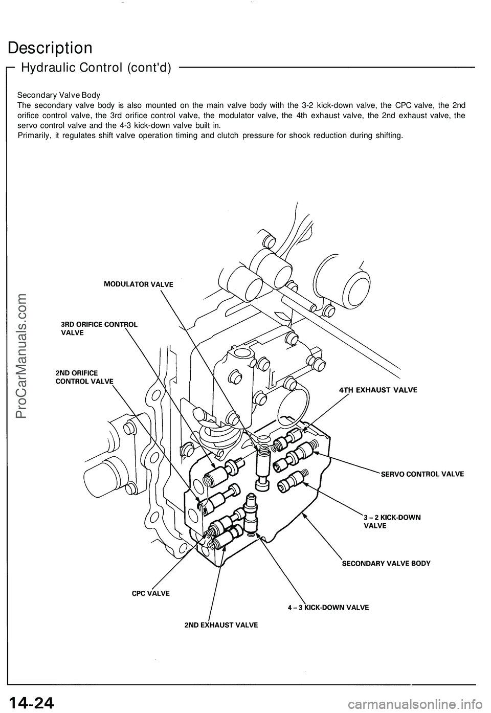
Secondary Valve Body
The secondary valve body is also mounted on the main valve body with the 3-2 kick-down valve, the CPC valve, the 2nd
orifice control valve, the 3rd orifice control valve, the modulator valve, the 4th exhaust valve, the 2nd exhaust valve, the
servo control valve and the 4-3 kick-down valve built in.
Primarily, it regulates shift valve operation timing and clutch pressure for shock reduction during shifting.
Hydraulic Control (cont'd)
DescriptionProCarManuals.com
Page 734 of 1503
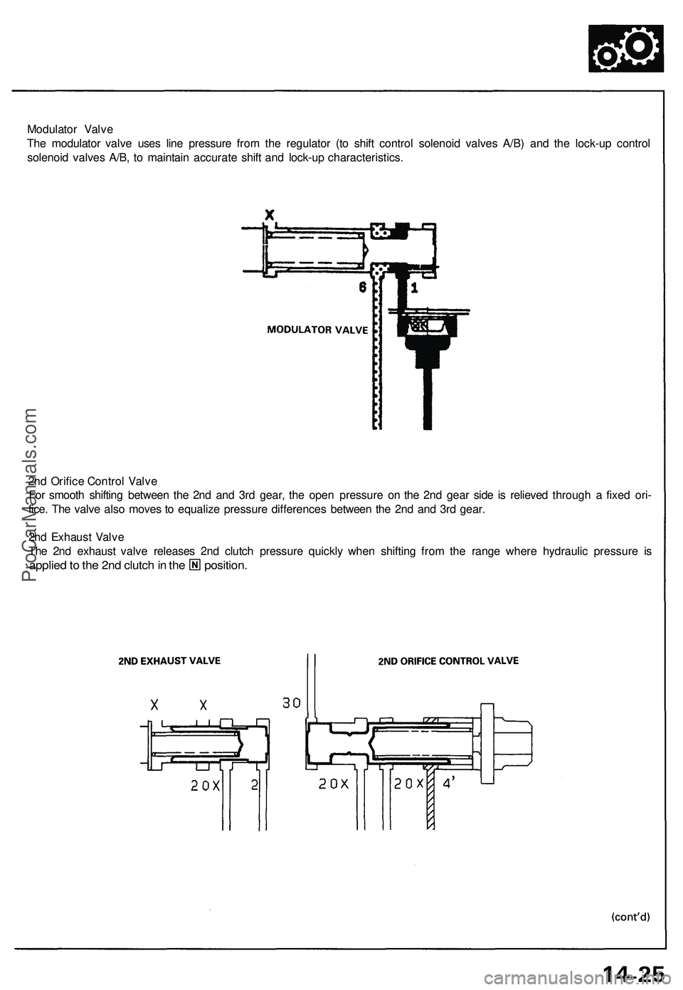
Modulator Valve
The modulator valve uses line pressure from the regulator (to shift control solenoid valves A/B) and the lock-up control
solenoid valves A/B, to maintain accurate shift and lock-up characteristics.
2nd Orifice Control Valve
For smooth shifting between the 2nd and 3rd gear, the open pressure on the 2nd gear side is relieved through a fixed ori-
fice. The valve also moves to equalize pressure differences between the 2nd and 3rd gear.
2nd Exhaust Valve
The 2nd exhaust valve releases 2nd clutch pressure quickly when shifting from the range where hydraulic pressure is
applied to the 2nd clutch in the position.ProCarManuals.com
Page 736 of 1503
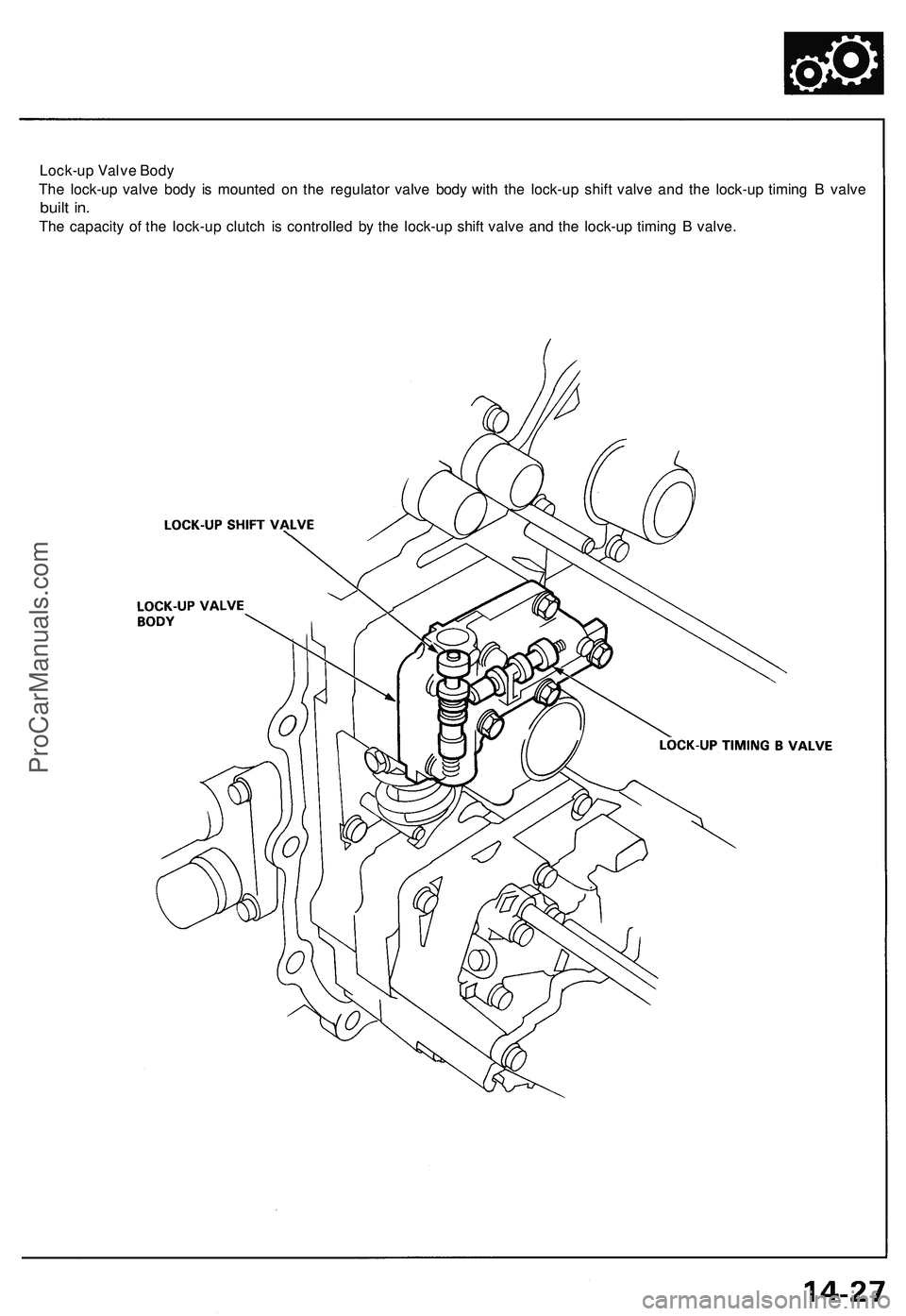
Lock-up Valve Body
The lock-up valve body is mounted on the regulator valve body with the lock-up shift valve and the lock-up timing B valve
built in.
The capacity of the lock-up clutch is controlled by the lock-up shift valve and the lock-up timing B valve.ProCarManuals.com
Page 738 of 1503
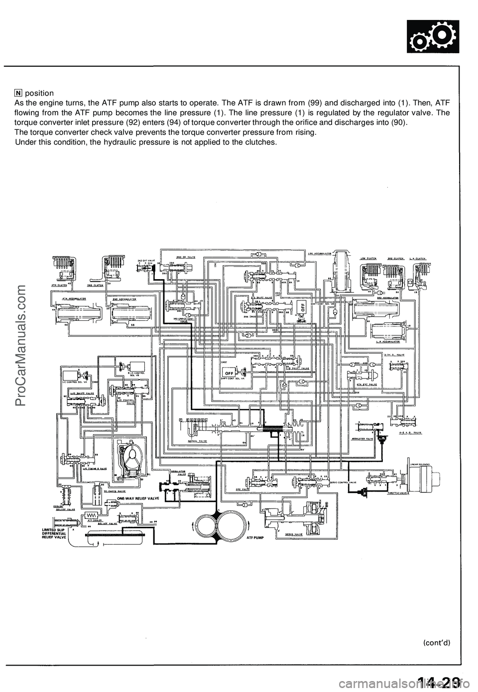
position
As the engine turns, the ATF pump also starts to operate. The ATF is drawn from (99) and discharged into (1). Then, ATF
flowing from the ATF pump becomes the line pressure (1). The line pressure (1) is regulated by the regulator valve. The
torque converter inlet pressure (92) enters (94) of torque converter through the orifice and discharges into (90).
The torque converter check valve prevents the torque converter pressure from rising.
Under this condition, the hydraulic pressure is not applied to the clutches.ProCarManuals.com
Page 739 of 1503
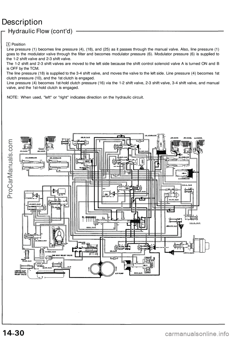
Position
Line pressure (1) becomes line pressure (4), (18), and (25) as it passes through the manual valve. Also, line pressure (1)
goes to the modulator valve through the filter and becomes modulator pressure (6). Modulator pressure (6) is supplied to
the 1-2 shift valve and 2-3 shift valve.
The 1-2 shift and 2-3 shift valves are moved to the left side because the shift control solenoid valve A is turned ON and B
is OFF by the
TCM.
The line pressure (18) is supplied to the 3-4 shift valve, and moves the valve to the left side. Line pressure (4) becomes 1st
clutch pressure (10), and the 1st clutch is engaged.
Line pressure (4) becomes 1st-hold clutch pressure (16) via the 1-2 shift valve, 2-3 shift valve, 3-4 shift valve, and manual
valve, and the 1st-hold clutch is engaged.
NOTE: When used, "left" or "right" indicates direction on the hydraulic circuit.
Hydraulic Flow (cont'd)
DescriptionProCarManuals.com
Page 740 of 1503
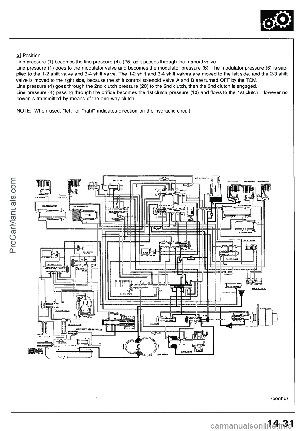
Position
Line pressure (1) becomes the line pressure (4), (25) as it passes through the manual valve.
Line pressure (1) goes to the modulator valve and becomes the modulator pressure (6). The modulator pressure (6) is sup-
plied to the 1-2 shift valve and 3-4 shift valve. The 1-2 shift and 3-4 shift valves are moved to the left side, and the 2-3 shift
valve is moved to the right side, because the shift control solenoid valve A and B are turned OFF by the TCM.
Line pressure (4) goes through the 2nd clutch pressure (20) to the 2nd clutch, then the 2nd clutch is engaged.
Line pressure (4) passing through the orifice becomes the 1st clutch pressure (10) and flows to the 1st clutch. However no
power is transmitted by means of the one-way clutch.
NOTE: When used, "left" or "right" indicates direction on the hydraulic circuit.ProCarManuals.com
