electrical Acura RDX 2015 Owner's Guide
[x] Cancel search | Manufacturer: ACURA, Model Year: 2015, Model line: RDX, Model: Acura RDX 2015Pages: 71, PDF Size: 18.23 MB
Page 15 of 71

22 || 23
INSTRUMENT P
ANEL
SAFETY
TABLE OF
CONTENTS
VISUAL INDEX
SAFETY
INFORMATION
INSTRUMENT PANEL
VEHICLE
CONTROLS
AUDIO AND
CONNECTIVITY
BLUETOOTH®
HANDSFREELINK®
ACURALINK®
INDEX
VOICE COMMAND INDEX
CLIENT
INFORMATION
SPECIFICATIONS
MAINTENANCE
HANDLING THE UNEXPECTED
DRIVING
NAVIGATION
Reporting Safety Defects
In the U.S.
If you believe that your vehicle has a defect which could cause a crash or could
cause injury or death, you should immediately inform the National Highway Traffic
Safety Administration (NHTSA) in addition to notifying American Honda Motor
Co., Inc.
If NHTSA receives similar complaints, it may open an investigation, and if it finds
that a safety defect exists in a group of vehicles, it may order a recall and remedy
campaign. However, NHTSA cannot become involved in individual problems
between you, your dealer, or American Honda Motor Co., Inc.
To contact NHTSA, you may call the Vehicle Safety Hotline toll-free at (888)
327-4236 (TTY: 1-800-424-9153); go to http://www.safercar.gov; or write to:
Administrator, NHTSA, 1200 New Jersey Avenue, SE., Washington, DC 20590. You
can also obtain other information about motor vehicle safety from http://www.
safercar.gov.
In Canada
If you believe that your vehicle has a defect which could cause a crash or could
cause injury or death, you should immediately inform Honda Canada, Inc., and you
may also inform Transport Canada.
If Transport Canada receives similar complaints, it may open an investigation, and
if it finds that a safety defect exists in a group of vehicles, it may lead to a recall
and remedy campaign. However, Transport Canada cannot become involved in
individual problems between you, your dealer, or Honda Canada, Inc.
To contact Transport Canada’s Defect Investigations and Recalls Division, you may
call (800) 333-0510. For more information on reporting safety defects or about
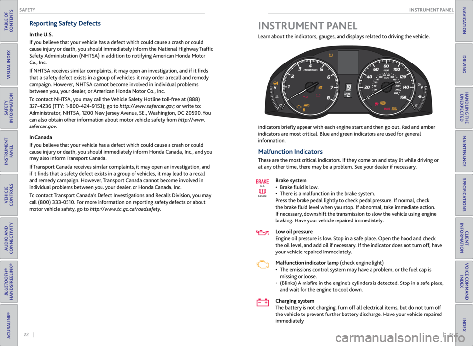
motor vehicle safety, go to http://www.tc.gc.ca/roadsafety. Learn about the indicators, gauges, and displays related to driving the vehicle.
Indicators briefly appear
with each engine start and then go out. Red and amber
indicators are most critical. Blue and green indicators are used for general
information.
Malfunction Indicators
These are the most critical indicators. If they come on and stay lit while driving or
at any other time, there may be a problem. See your dealer if necessary.
Brake system
• Brake fluid is low.
• There is a malfunction in the brake system.
Press the brake pedal lightly to check pedal pressure. If normal, check
the brake fluid level when you stop. If abnormal, take immediate action.
If necessary, downshift the transmission to slow the vehicle using engine
braking. Have your vehicle repaired immediately.
Low oil pressure
Engine oil pressure is low. Stop in a safe place. Open the hood and check
the oil level, and add oil if necessary. If the indicator does not turn off, have
your vehicle repaired immediately.
Malfunction indicator lamp (check engine light)
• The emissions control system may have a problem, or the fuel cap is
missing or loose.
• (Blinks) A misfire in the engine’s cylinders is detected. Stop in a safe place,
and wait for the engine to cool down.
Charging system
The battery is not charging. Turn off all electrical items, but do not turn off
the vehicle to prevent further battery discharge. Have your vehicle repaired
immediately.
Canada U.S.
INSTRUMENT P
ANEL
Page 45 of 71

82 || 83
DRIVING
DRIVING
TABLE OF
CONTENTS
VISUAL INDEX
SAFETY
INFORMATION
INSTRUMENT PANEL
VEHICLE
CONTROLS
AUDIO AND
CONNECTIVITY
BLUETOOTH®
HANDSFREELINK®
ACURALINK®
INDEX
VOICE COMMAND INDEX
CLIENT
INFORMATION
SPECIFICATIONS
MAINTENANCE
HANDLING THE UNEXPECTED
DRIVING
NAVIGATION
Pre-tow checklist
When preparing to tow, and before driving away, be sure to check the following:
• Avoid towing a trailer during your vehicle’s first 600 miles (1,000 km).
• The vehicle has been properly serviced, and the suspension and the cooling
system are in good operating condition.
• The trailer has been properly serviced and is in good condition.
• All weights and loads are within limits. Never exceed the gross weight ratings.
• Check if all loads are within limits at a public scale. If a public scale is not
available, add the estimated weight of your cargo load to the weight of your
trailer (as quoted by the manufacturer) and the tongue load.
• The hitch, safety chains, and any other attachments are secure.
• All items in or on the trailer are properly secured and cannot shift while you
drive.
Towing a Trailer
Your vehicle can tow a trailer if you carefully observe the load limits, use the
proper equipment, and follow the towing guidelines. See the Owner’s Manual on
the Owner Information CD or visit owners.acura.com (U.S.) or www.myacura.com
(Canada) for more information.
Towing Load Limits
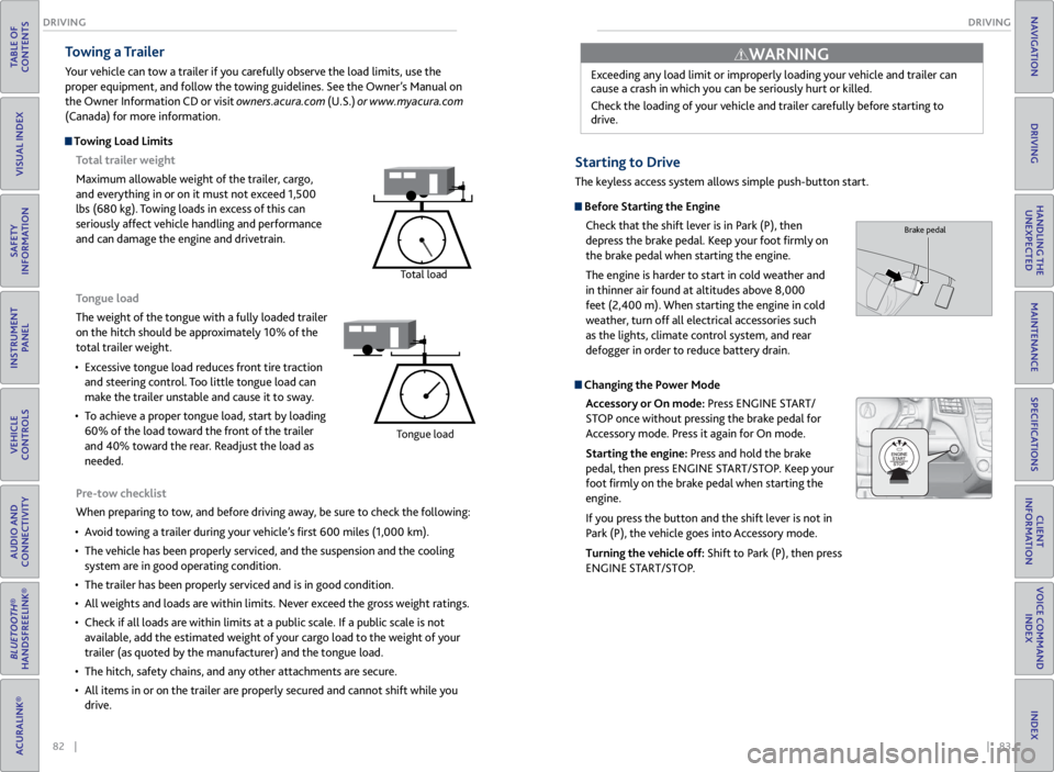
Total trailer weight
Maximum allowable weight of the trailer, cargo,
and everything in or on it must not exceed 1,500
lbs (680 kg). Towing loads in excess of this can
seriously affect vehicle handling and performance
and can damage the engine and drivetrain.
Total load
Tongue load
The weight of the tongue with a fully loaded trailer
on the hitch should be approximately 10% of the
total trailer weight.
• Excessive tongue load reduces front tire traction
and steering control. Too little tongue load can
make the trailer unstable and cause it to sway.
• To achieve a proper tongue load, start by loading
60% of the load toward the front of the trailer
and 40% toward the rear. Readjust the load as
needed.
Tongue load
Exceeding any load limit or improperly loading your vehicle and trailer can
cause a crash in which you can be seriously hurt or killed.
Check the loading of your vehicle and trailer carefully before starting to
drive.
WARNING
Starting to Drive
The keyless access system allows simple push-button start.
Before Starting the Engine
Check that the shift lever is in Park (P), then
depress the brake pedal. Keep your foot firmly on
the brake pedal when starting the engine.
The engine is harder to start in cold weather and
in thinner air found at altitudes above 8,000
feet (2,400 m). When starting the engine in cold
weather, turn off all electrical accessories such
as the lights, climate control system, and rear
defogger in order to reduce battery drain.
Changing the Power Mode
Accessory or On mode: Press ENGINE START/
STOP once without pressing the brake pedal for
Accessory mode. Press it again for On mode.
Starting the engine: Press and hold the brake
pedal, then press ENGINE START/STOP. Keep your
foot firmly on the brake pedal when starting the
engine.
If you press the button and the shift lever is not in
Park (P), the vehicle goes into Accessory mode.
Turning the vehicle off: Shift to Park (P), then press
ENGINE START/STOP.
Brake pedal
Page 53 of 71

98 || 99
HANDLING THE UNEXPECTED
HANDLING THE UNEXPECTED
TABLE OF
CONTENTS
VISUAL INDEX
SAFETY
INFORMATION
INSTRUMENT PANEL
VEHICLE
CONTROLS
AUDIO AND
CONNECTIVITY
BLUETOOTH®
HANDSFREELINK®
ACURALINK®
INDEX
VOICE COMMAND INDEX
CLIENT
INFORMATION
SPECIFICATIONS
MAINTENANCE
HANDLING THE UNEXPECTED
DRIVING
NAVIGATION
Replacing the Flat Tire
1. Remove the wheel nuts and flat tire.
2. Mount the compact spare tire. Replace the wheel
nuts, and lightly tighten them.
3. Lower the vehicle and remove the jack. Tighten
the wheel nuts in the order indicated in the
image. Go around, tightening the nuts, two to
three times in this order. Do not overtighten the
wheel nuts.
Storing the Flat Tire
1. Remove the center cap and place the flat tire
face up in the spare tire well.
2. Remove the spacer cone from the wing bolt for
the spare tire, and insert the wing bolt for the
regular tire back on the bolt. Secure the flat tire
with the wing bolt.
3. Securely store the jack and wheel nut wrench
back in the tool case. Store the case in the cargo
area.
Loose items can fly around the interior in a crash and can seriously injure the
occupants.
Store the wheel, jack, and tools securely before driving.
WARNING
Wing
bolt
Spacer
cone For normal
tire
For compact
spare tire
Fuse Locations
If any electrical devices are not working, turn the vehicle off and check to see if any
applicable fuse is blown. Fuse locations are shown on the fuse box cover. Locate the
fuse by the fuse number and box cover number.
Engine Compartment Fuse Box Located near the brake fluid reservoir. Push the tabs to open the box.
*1: Models with halogen low beam
headlight bulb s
*2: Models with high voltage discharge tube
bulb s
9��
10
��
11Oil Leve l7.5A
12 Fog Lights*(20A )
13Power Tailgate Closer*(20A )
14 Hazar
d10A
15IGP215A
16 IG Coil 15A
17Stop10A
18 Horn 10A
19ACM10A
20 Right Headlight Low Beam 10
A*1
15A*2
21MG Clutch7.5A
22 DB
W15A
23Left Headlight Low Beam10A*1
15A*2
24 ACC10A
25FI Main(15A )
26 Trailer (20A )
27Small20A
28 Interior Lights 7.5A
29Back Up10 A
Circuit ProtectedAmps
Circuit Protecte dAmps
1
EPS70A
Power Tailgate Motor*(40A )
ABS/VSA FS R20A
ABS/VSA Motor40A
E-DPS30A
Main Fuse120A
2
ST CUT50 A
Fuse Box Main 160A
Fuse Box Main 260A
IG Main 50A
Headlight Washer(30A )
Sub Fan Moto r30A
Rear Defogger 40A
Main Fan Motor 30A
Headlight Main 30A
Blowe r4 0A
3
Driver's Power Seat Sliding 20A
Driver's Power Seat Reclinin g20A
Passenger's Power Seat Sliding20 A
Passenger' s Power Seat Recl ining20 A
4� �
5STR Diagnosis Fuse7.5A
6� �
7��
8� �
Page 54 of 71

100 || 101
HANDLING THE UNEXPECTED
HANDLING THE UNEXPECTED
TABLE OF
CONTENTS
VISUAL INDEX
SAFETY
INFORMATION
INSTRUMENT PANEL
VEHICLE
CONTROLS
AUDIO AND
CONNECTIVITY
BLUETOOTH®
HANDSFREELINK®
ACURALINK®
INDEX
VOICE COMMAND INDEX
CLIENT
INFORMATION
SPECIFICATIONS
MAINTENANCE
HANDLING THE UNEXPECTED
DRIVING
NAVIGATION
Interior Fuse Box
Located under the dashboard.
Circuit Protecte dAmps
1��
2ACG15 A
3SRS10A
4Fuel Pump15A
5Meter7.5A
6Option7.5A
7VB SOL10 A
8Front Right Side
Door Lock Motor (Unlock)15 A
9Rear Left Side
Door Lock Motor (Unlock)15 A
10 Power Lumba r7.5A
11Moonroof20 A
12 Accessory Power Socket
(Center Console )15
A
13Washer Main15A
14 Seat Heaters 15A
15Driver’s Door Lock Motor
(Unlock)10A
16 ��
17��
18 ��
19ACC7.5A
20 ACC Key Lock 7.5A
21Daytime Running Lights7.5A
22 A/
C7.5A
23Rear Wipe r10A
24 ABS/VS
A7.5A
25��
26 Audio Am
p20A
27Accessory Power Socket
(Front)15 A
28
��
29ODS7. 5A
30 Driver’s Door Lock Motor
(Lock) 10
A
Circuit Protecte dAmps
31Smart10A
32 Front Right Side
Door Lock Motor (Lock )15
A
33Rear Left Side
Door Lock Motor (Lock )15A
34 Small Lights 7.5A
35Illumination7.5A
36 Rear Wiper Main 10A
37��
38 Left Headlight High Beam 10A
39Right Headlight High Beam10 A
40 TPMS 7.5A
41Door Lock20 A
42 Driver’s Power Window 20A
43Rear Right Side Power
Window20A
44 Front Right Side Power
Window 20
A
45Rear Left Side Power
Window20A
46 Wiper 30A
Fuse box
Fuse label
Inspecting and Changing Fuses
1. Turn the vehicle off, including the headlights and
accessories.
2. Remove the fuse box cover.
3. Check the large fuse in the engine compartment.
If the fuse is blown, use a Phillips-head
screwdriver to remove the screws and replace
the fuse with a new one. Reinstall the screws.
4. Inspect the small fuses in the engine
compartment and the vehicle interior.
If there is a burned out fuse, remove it with the
fuse puller and replace it with a new one.
Replacing a fuse with one that has a higher rating greatly increases the chances of
damaging the electrical system.
NOTICE
Blown fuse
Combined
fuse Fuse puller