gearbox ACURA RL KA9 1996 Service Repair Manual
[x] Cancel search | Manufacturer: ACURA, Model Year: 1996, Model line: RL KA9, Model: ACURA RL KA9 1996Pages: 1954, PDF Size: 61.44 MB
Page 309 of 1954
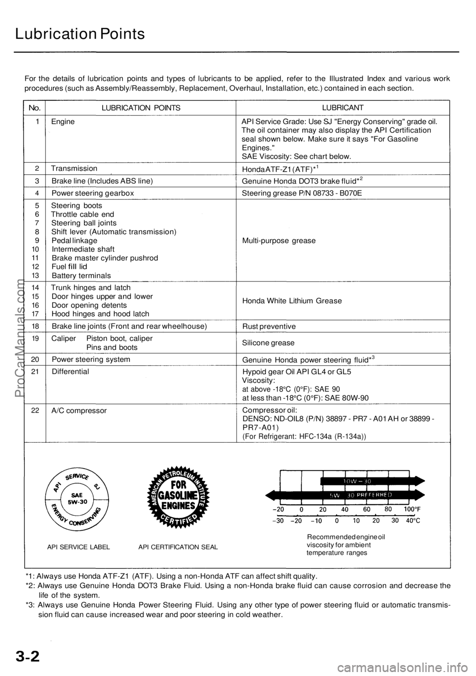
Lubrication Points
For the details of lubrication points and types of lubricants to be applied, refer to the Illustrated Index and various work
procedures (such as Assembly/Reassembly, Replacement, Overhaul, Installation, etc.) contained in each section.
No.
1
2
3
4
5
6
7
8
9
10
11
12
13
14
15
16
17
18
19
20
21
22
LUBRICATION POINTS
Engine
Transmission
Brake line (Includes ABS line)
Power steering gearbox
Steering boots
Throttle cable end
Steering ball joints
Shift lever (Automatic transmission)
Pedal linkage
Intermediate shaft
Brake master cylinder pushrod
Fuel
fill
lid
Battery terminals
Trunk hinges and latch
Door hinges upper and lower
Door opening detents
Hood hinges and hood latch
Brake line joints (Front and rear wheelhouse)
Caliper Piston boot, caliper
Pins and boots
Power steering system
Differential
A/C compressor
API SERVICE LABEL API CERTIFICATION SEAL
LUBRICANT
API Service Grade: Use SJ "Energy Conserving" grade oil.
The oil container may also display the API Certification
seal shown below. Make sure it says "For Gasoline
Engines."
SAE Viscosity: See chart below.
Honda ATF-Z1 (ATF)*1
Genuine Honda DOT3 brake fluid*2
Steering grease P/N 08733 - B070E
Multi-purpose grease
Honda White Lithium Grease
Rust preventive
Silicone grease
Genuine Honda power steering fluid*3
Hypoid gear Oil API GL4 or GL5
Viscosity:
at above -18°C (0°F): SAE 90
at less than -18°C (0°F): SAE 80W-90
Compressor oil:
DENSO: ND-OIL8 (P/N) 38897 - PR7 - A01 AH or 38899 -
PR7-A01)
(For Refrigerant: HFC-134a (R-134a))
Recommended engine oil
viscosity for ambient
temperature ranges
*1: Always use Honda ATF-Z1 (ATF). Using a non-Honda ATF can affect shift quality.
*2: Always use Genuine Honda DOT3 Brake Fluid. Using a non-Honda brake fluid can cause corrosion and decrease the
life of the system.
*3: Always use Genuine Honda Power Steering Fluid. Using any other type of power steering fluid or automatic transmis-
sion fluid can cause increased wear and poor steering in cold weather.ProCarManuals.com
Page 825 of 1954
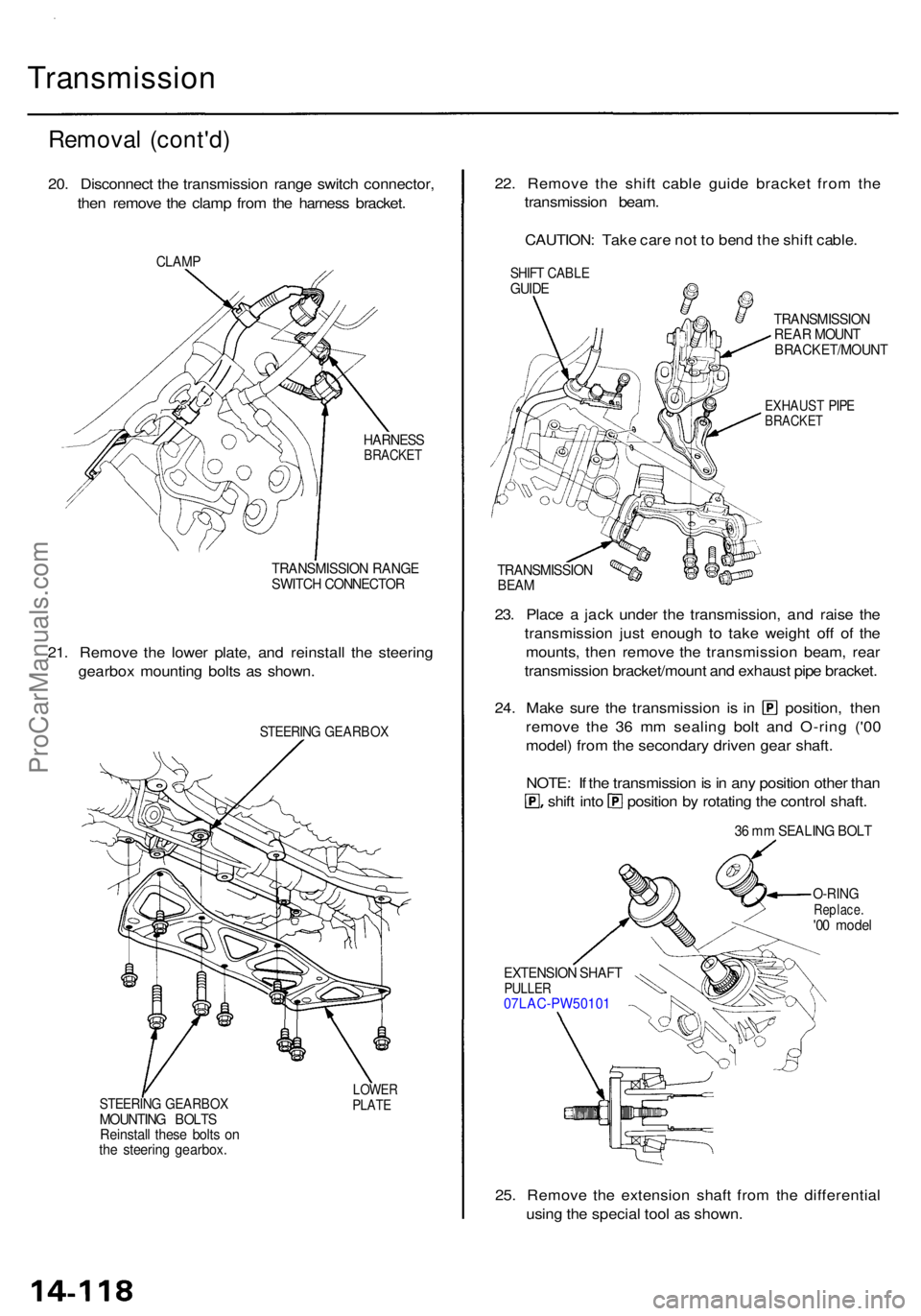
Transmission
Removal (cont'd )
20. Disconnec t th e transmissio n rang e switc h connector ,
the n remov e th e clam p fro m th e harnes s bracket .
CLAMP
HARNES SBRACKE T
TRANSMISSIO N RANG E
SWITC H CONNECTO R
21. Remov e th e lowe r plate , an d reinstal l th e steerin g
gearbo x mountin g bolt s a s shown .
STEERIN G GEARBO X
STEERING GEARBO XMOUNTING BOLT S
Reinstal l thes e bolt s o n
th e steerin g gearbox .
LOWERPLATE
22. Remov e th e shif t cabl e guid e bracke t fro m th e
transmissio n beam .
CAUTION : Tak e car e no t t o ben d th e shif t cable .
TRANSMISSIO N
REA R MOUN T
BRACKET/MOUN T
EXHAUST PIP EBRACKE T
TRANSMISSIO NBEAM
23. Plac e a jac k unde r th e transmission , an d rais e th e
transmissio n jus t enoug h t o tak e weigh t of f o f th e
mounts , the n remov e th e transmissio n beam , rea r
transmissio n bracket/moun t an d exhaus t pip e bracket .
24. Mak e sur e th e transmissio n i s i n position , the n
remov e th e 3 6 m m sealin g bol t an d O-rin g ('0 0
model ) fro m th e secondar y drive n gea r shaft .
NOTE : I f th e transmissio n is in an y positio n othe r tha n
shift int o positio n b y rotatin g th e contro l shaft .
36 m m SEALIN G BOL T
O-RIN GReplace .'00 mode l
EXTENSIO N SHAF T
PULLE R07LAC-PW5010 1
25. Remov e th e extensio n shaf t fro m th e differentia l
usin g th e specia l too l a s shown .
SHIFT CABL EGUIDE
ProCarManuals.com
Page 968 of 1954
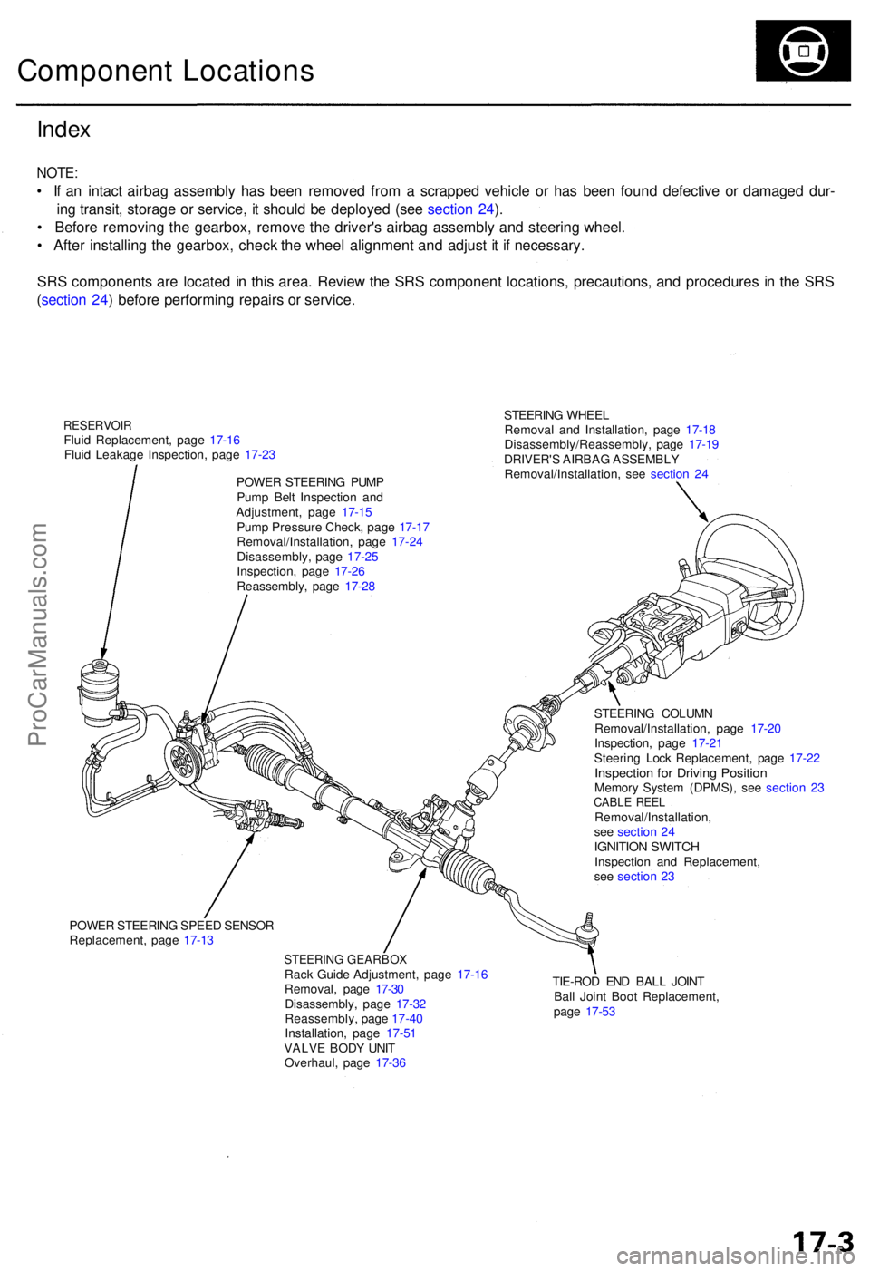
STEERING WHEE L
Remova l an d Installation , pag e 17-1 8
Disassembly/Reassembly , pag e 17-1 9
DRIVER' S AIRBA G ASSEMBL Y
Removal/Installation , se e sectio n 2 4
Inde x
NOTE :
• I f a n intac t airba g assembl y ha s bee n remove d fro m a scrappe d vehicl e o r ha s bee n foun d defectiv e o r damage d dur -
in g transit , storag e o r service , i t shoul d b e deploye d (se e sectio n 24 ).
• Befor e removin g th e gearbox , remov e th e driver' s airba g assembl y an d steerin g wheel .
• Afte r installin g th e gearbox , chec k th e whee l alignmen t an d adjus t i t i f necessary .
SR S component s ar e locate d in thi s area . Revie w th e SR S componen t locations , precautions , an d procedure s i n th e SR S
( sectio n 24 ) befor e performin g repair s o r service .
Componen t Location s
RESERVOI RFluid Replacement , pag e 17-1 6
Flui d Leakag e Inspection , pag e 17-2 3
POWE R STEERIN G PUM P
Pum p Bel t Inspectio n an d
Adjustment , pag e 17-1 5
Pum p Pressur e Check , pag e 17-1 7
Removal/Installation , pag e 17-2 4
Disassembly , pag e 17-2 5
Inspection , pag e 17-2 6
Reassembly , pag e 17-2 8
POWE R STEERIN G SPEE D SENSO R
Replacement , pag e 17-1 3
STEERIN G GEARBO XRack Guid e Adjustment , pag e 17-1 6
Removal , pag e 17-3 0
Disassembly , pag e 17-3 2
Reassembly , pag e 17-4 0
Installation , pag e 17-5 1
VALV E BOD Y UNI T
Overhaul , pag e 17-3 6 TIE-RO
D EN D BAL L JOIN T
Bal l Join t Boo t Replacement ,
pag e 17-5 3
STEERIN
G COLUM N
Removal/Installation , pag e 17-2 0
Inspection , pag e 17-2 1
Steerin g Loc k Replacement , pag e 17-2 2
Inspectio n fo r Drivin g Positio nMemory Syste m (DPMS), see sectio n 2 3CABL E REE LRemoval/Installation ,
se e sectio n 2 4
IGNITIO N SWITC HInspectio n an d Replacement ,
se e sectio n 2 3
ProCarManuals.com
Page 971 of 1954
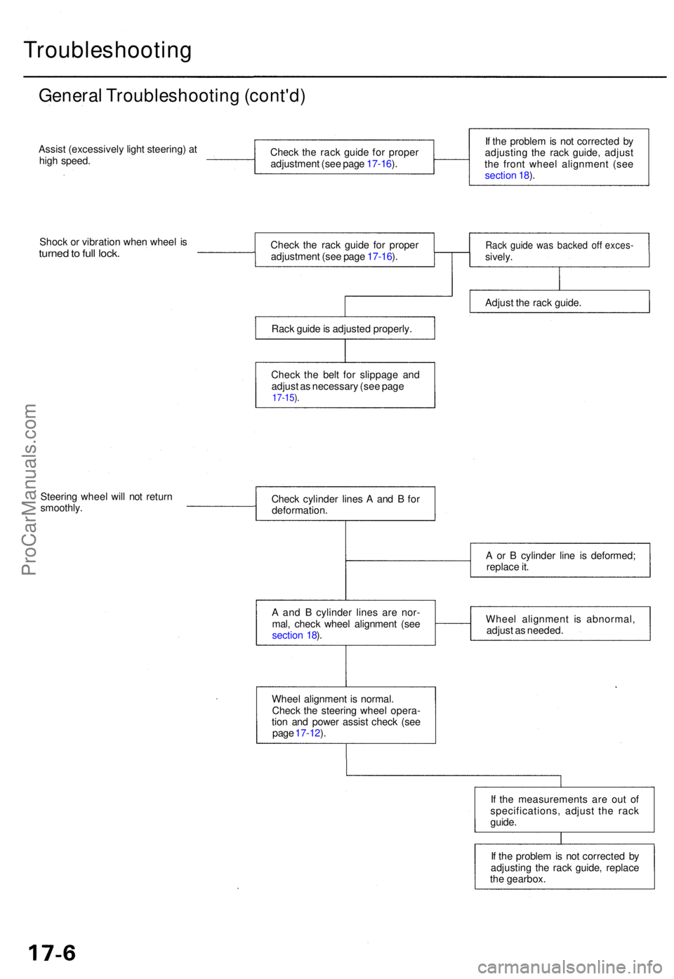
Troubleshooting
General Troubleshootin g (cont'd )
Assist (excessivel y ligh t steering ) a t
hig h speed .
Shoc k o r vibratio n whe n whee l i s
turne d to ful l lock .
Steerin g whee l wil l no t retur n
smoothly .
If th e proble m is no t correcte d b y
adjustin g th e rac k guide , replace
th e gearbox .
I
f th e measurement s ar e ou t o f
specifications , adjus t th e rac k
guide .
Whee
l alignmen t i s normal .
Chec k th e steerin g whee l opera -
tio n an d powe r assis t chec k (se e
pag e 17-12 ).
A
an d B cylinde r line s ar e nor -
mal , chec k whee l alignmen t (se e
sectio n 18 ). Whee
l alignmen t i s abnormal ,
adjus t a s needed .
A
o r B cylinde r lin e i s deformed ;
replac e it .
Chec
k cylinde r line s A an d B fo r
deformation .
Chec
k th e rac k guid e fo r prope r
adjustmen t (se e pag e 17-16 ).
Chec k th e rac k guid e fo r prope r
adjustmen t (se e pag e 17-16 ).
Rac k guid e is adjuste d properly .
Chec k th e bel t fo r slippag e an d
adjus t a s necessar y (se e pag e
17-15 ).
If th e proble m is no t correcte d b y
adjustin g th e rac k guide , adjus t
th e fron t whee l alignmen t (se e
sectio n 18 ).
Rac k guid e wa s backe d of f exces -sively.
Adjus t th e rac k guide .
ProCarManuals.com
Page 972 of 1954
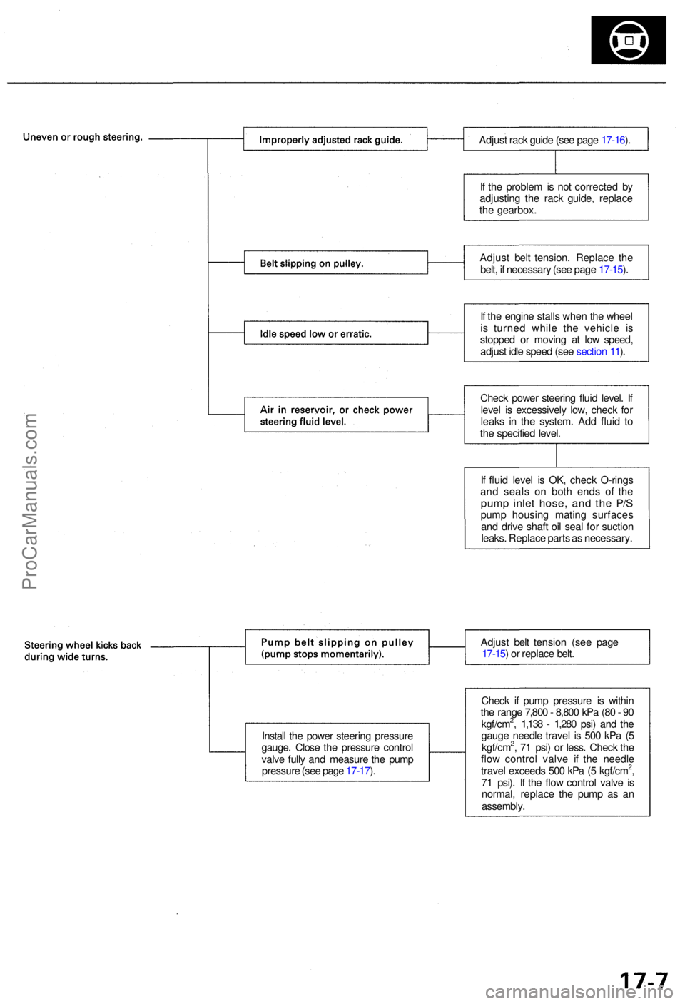
Install th e powe r steerin g pressur e
gauge . Clos e th e pressur e contro l
valv e full y an d measur e th e pum p
pressur e (se e pag e 17-17 ). Adjus
t bel t tensio n (se e pag e
17-15 ) o r replac e belt .
Adjus
t rac k guid e (se e pag e 17-16 ).
I f th e proble m is no t correcte d b y
adjustin g th e rac k guide , replac e
th e gearbox .
Adjus t bel t tension . Replac e th e
belt , i f necessar y (se e pag e 17-15 ).
I f th e engin e stall s whe n th e whee l
i s turne d whil e th e vehicl e i s
stoppe d o r movin g a t lo w speed ,
adjus t idl e spee d (se e sectio n 11 ).
Chec k powe r steerin g flui d level . I f
leve l i s excessivel y low , chec k fo r
leak s i n th e system . Ad d flui d t o
th e specifie d level .
I f flui d leve l i s OK , chec k O-ring s
an d seal s o n bot h end s o f th e
pum p inle t hose , an d th e P/ Spum p housin g matin g surface s
an d driv e shaf t oi l sea l fo r suctio n
leaks . Replac e part s a s necessary .
Chec k i f pum p pressur e i s withi n
th e rang e 7,80 0 - 8,80 0 kP a (8 0 - 9 0
kgf/cm
2, 1,13 8 - 1,28 0 psi ) an d th e
gaug e needl e trave l i s 50 0 kP a ( 5
kgf/cm
2, 7 1 psi ) o r less . Chec k th e
flo w contro l valv e i f th e needl e
trave l exceed s 50 0 kP a ( 5 kgf/cm
2,
7 1 psi) . I f th e flo w contro l valv e i s
normal , replac e th e pum p a s a n
assembly .
ProCarManuals.com
Page 979 of 1954
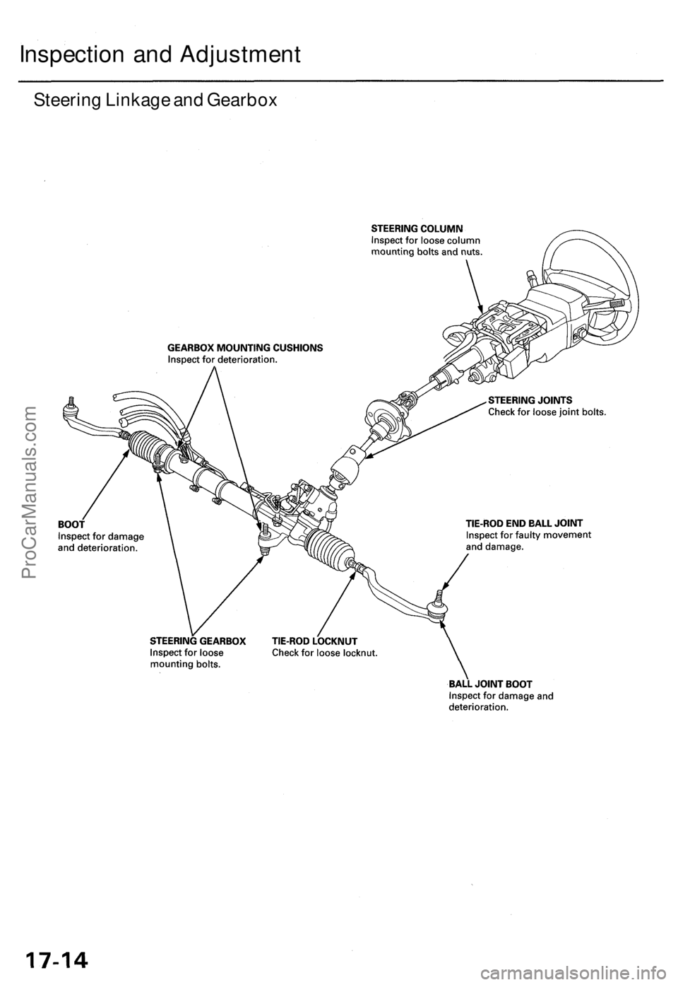
Steering Linkage and Gearbox
Inspection and AdjustmentProCarManuals.com
Page 981 of 1954
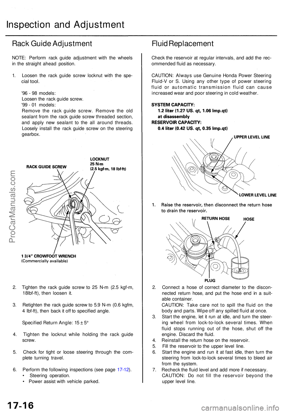
2. Tighte n th e rac k guid e scre w to 2 5 N- m (2. 5 kgf-m ,
18lbf-ft) , the n loose n it .
3 . Retighte n th e rac k guid e scre w to 5. 9 N- m (0. 6 kgfm ,
4 Ibf-ft) , the n bac k it of f t o specifie d angle .
Specifie d Retur n Angle : 1 5 ± 5°
4 . Tighte n th e locknu t whil e holdin g th e rac k guid e
screw .
5 . Chec k fo r tigh t o r loos e steerin g throug h th e com -
plet e turnin g travel .
6 . Perfor m th e followin g inspection s (se e pag e 17-12 ).
• Steerin g operation .
• Powe r assis t wit h vehicl e parked . 2
. Connec t a hos e o f correc t diamete r t o th e discon -
necte d retur n hose , an d pu t th e hos e en d i n a suit -
abl e container .
CAUTION : Tak e car e no t t o spil l th e flui d o n th e
bod y an d parts . Wip e of f an y spille d flui d a t once .
3 . Star t th e engine , le t i t ru n a t idle , an d tur n th e steer -
in g whee l fro m lock-to-loc k severa l times . Whe n
flui d stop s runnin g ou t of the hose , shu t of f th e
engine . Discar d th e fluid .
4 . Reinstal l th e retur n hos e o n th e reservoir .
5 . Fil l th e reservoi r t o th e uppe r leve l line .
6 . Star t th e engin e an d ru n i t a t fas t idle , the n tur n th e
steerin g fro m lock-to-loc k severa l time s t o blee d ai r
fro m th e system .
7 . Rechec k th e flui d leve l an d ad d mor e if necessary .
CAUTION : D o no t fil l th e reservoi r beyon d th e
uppe r leve l line .
Inspectio n an d Adjustmen t
Rack Guid e Adjustmen t
NOTE: Perfor m rac k guid e adjustmen t wit h th e wheel s
i n th e straigh t ahea d position .
1 . Loose n th e rac k guid e scre w locknu t wit h th e spe -
cial tool .
'96 - 9 8 models :
Loose n th e rac k guid e screw .
'9 9 - 0 1 models :
Remov e th e rac k guid e screw . Remov e th e ol d
sealan t fro m th e rac k guid e scre w threade d section ,
an d appl y ne w sealan t t o th e al l aroun d threads .
Loosel y instal l th e rac k guid e scre w o n th e steerin g
gearbox .
Fluid Replacemen t
Check th e reservoi r a t regula r intervals , an d ad d th e rec -
ommende d flui d a s necessary .
CAUTION : Alway s us e Genuin e Hond a Powe r Steerin g
Fluid- V o r S . Usin g an y othe r typ e o f powe r steerin g
flui d o r automati c transmissio n flui d ca n caus e
increase d wea r an d poo r steerin g in col d weather .
ProCarManuals.com
Page 982 of 1954
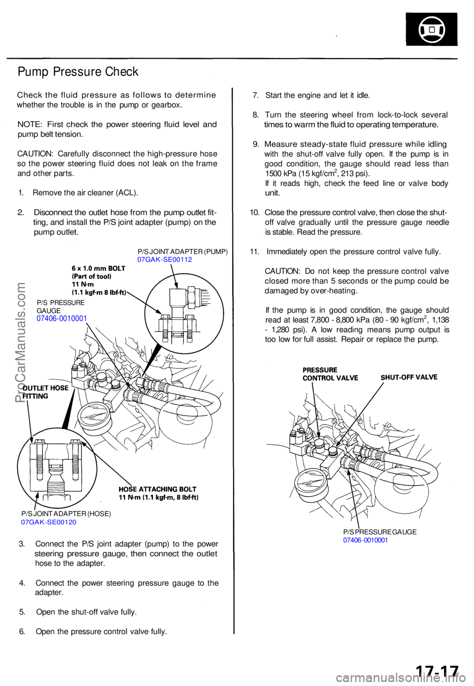
Pump Pressur e Chec k
Check th e flui d pressur e a s follow s t o determin e
whether th e troubl e i s i n th e pum p o r gearbox .
NOTE: Firs t chec k th e powe r steerin g flui d leve l an d
pum p bel t tension .
CAUTION : Carefull y disconnec t th e high-pressur e hos e
s o th e powe r steerin g flui d doe s no t lea k o n th e fram e
an d othe r parts .
1 . Remov e th e ai r cleane r (ACL) .
2. Disconnec t th e outle t hos e fro m th e pum p outle t fit -
ting , an d instal l th e P/ S join t adapte r (pump ) o n th e
pum p outlet .
P/S JOIN T ADAPTE R (PUMP )
07GAK-SE0011 2
P/S PRESSUR EGAUGE07406-0010001
P/S JOIN T ADAPTE R (HOSE )07GAK-SE0012 0
3. Connec t th e P/ S join t adapte r (pump ) t o th e powe r
steerin g pressur e gauge , the n connec t th e outle t
hose t o th e adapter .
4 . Connec t th e powe r steerin g pressur e gaug e t o th e
adapter .
5 . Ope n th e shut-of f valv e fully .
6 . Ope n th e pressur e contro l valv e fully .
P/S PRESSUR E GAUG E
0740 6-001000 1
7. Star t th e engin e an d le t i t idle .
8 . Tur n th e steerin g whee l fro m lock-to-loc k severa l
times to war m th e flui d to operatin g temperature .
9. Measur e steady-stat e flui d pressur e whil e idlin g
with th e shut-of f valv e full y open . I f th e pum p i s i n
goo d condition , th e gaug e shoul d rea d les s tha n
150 0 kP a (1 5 kgf/cm
2, 21 3 psi) .
I f i t read s high , chec k th e fee d lin e o r valv e bod y
unit.
10. Clos e th e pressur e contro l valve , the n clos e th e shut -
off valv e graduall y unti l th e pressur e gaug e needl e
i s stable . Rea d th e pressure .
11 . Immediatel y ope n th e pressur e contro l valv e fully .
CAUTION : D o no t kee p th e pressur e contro l valv e
close d mor e tha n 5 second s o r th e pum p coul d b e
damage d b y over-heating .
I f th e pum p i s i n goo d condition , th e gaug e shoul d
rea d a t leas t 7,80 0 - 8,80 0 kP a (8 0 - 9 0 kgf/cm
2, 1,13 8
- 1,28 0 psi) . A lo w readin g mean s pum p outpu t i s
to o lo w fo r ful l assist . Repai r o r replac e th e pump .
ProCarManuals.com
Page 1000 of 1954
Power Steering Gearbox
Removal (cont'd)
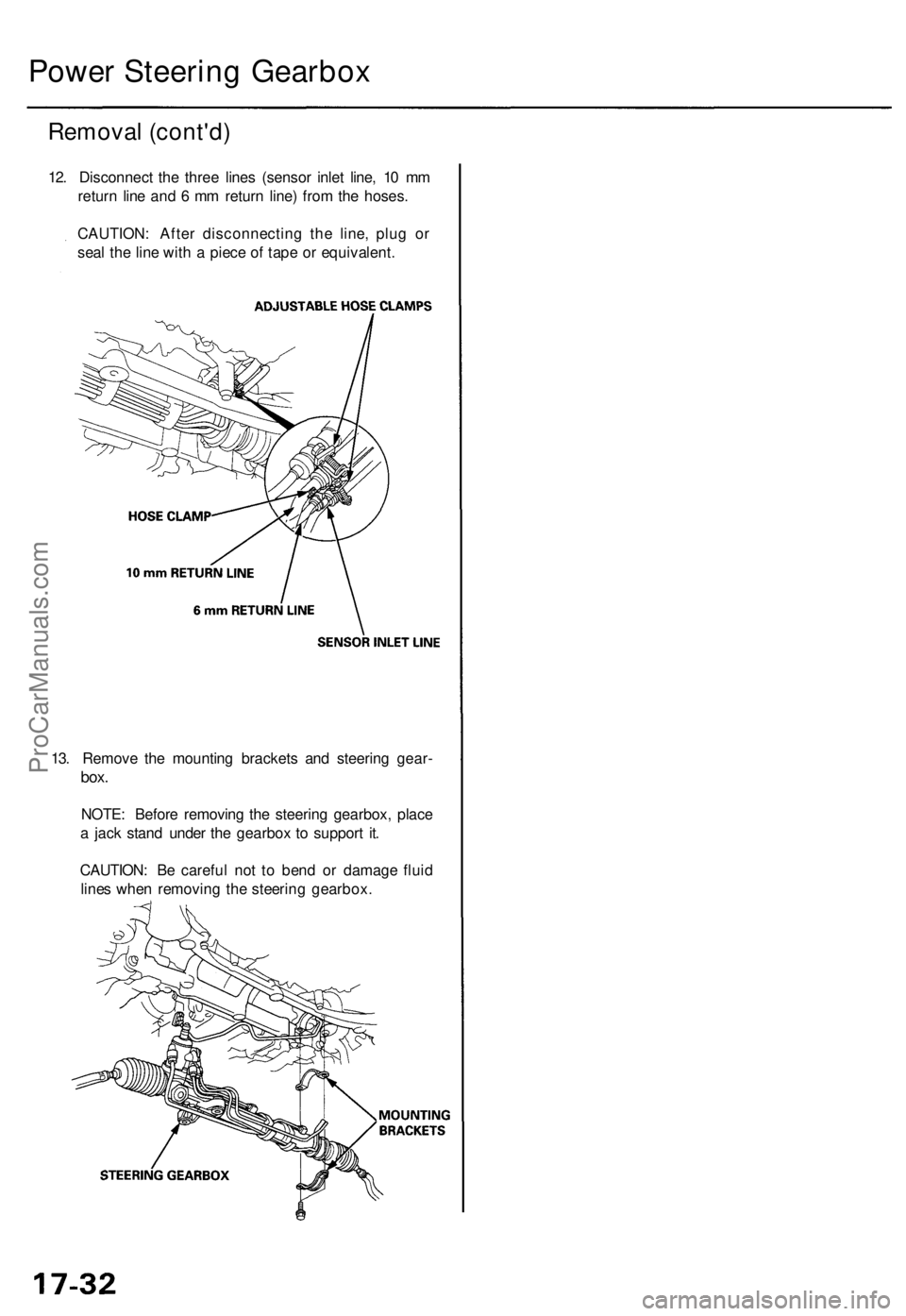
12. Disconnect the three lines (sensor inlet line, 10 mm
return line and 6 mm return line) from the hoses.
CAUTION: After disconnecting the line, plug or
seal the line with a piece of tape or equivalent.
13. Remove the mounting brackets and steering gear-
box.
NOTE: Before removing the steering gearbox, place
a jack stand under the gearbox to support it.
CAUTION: Be careful not to bend or damage fluid
lines when removing the steering gearbox.ProCarManuals.com
Page 1001 of 1954
Disassembly
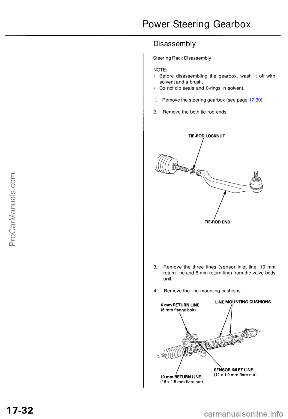
Steering Rac k Disassembl y
NOTE:
• Befor e disassemblin g th e gearbox , was h i t of f wit h
solven t an d a brush .
• D o no t di p seal s an d 0-ring s i n solvent .
1 . Remov e th e steerin g gearbo x (se e pag e 17-30 ).
2 . Remov e th e bot h tie-ro d ends .
3 . Remov e th e thre e line s (senso r inle t line , 1 0 m m
retur n lin e an d 6 m m retur n line ) fro m th e valv e bod y
unit.
4. Remov e th e lin e mountin g cushions .
Power Steerin g Gearbo x
ProCarManuals.com