low beam ACURA RL KA9 1996 Service Repair Manual
[x] Cancel search | Manufacturer: ACURA, Model Year: 1996, Model line: RL KA9, Model: ACURA RL KA9 1996Pages: 1954, PDF Size: 61.44 MB
Page 267 of 1954

Navigation System
System Diagnosis Mode (cont'd)
Black Raster
The entire display must be shown in black.
Test Pattern
The chart below; shows the colors being used for the
map and menu screens. This is for factory use only. To
check the color signal use the "RGB Color" diagnostic
found under the Monitor Check menu item.
Monitor Adjustment
This allows the navigation display to be centered. Use
the joystick to move the picture up/down or left/right. It
is unlikely that you will ever need to adjust the monitor
position. The "Default" button will reset the display
position to factory specifications.
Touch Panel
The panel touch sensing system consists of 9 horizontal
and 20 vertical infrared beams. Touching the screen
blocks both a horizontal and a vertical beam. Every pos-
sible touch position is shown on this diagnostic screen.
Touching one of these areas should cause its color to
reverse, and sound a "beep". If any areas of the screen
either don't respond, or respond at some other location
when touched, then replace the display unit. The
"Display" diagnostic listed in Unit Check provides an
additional method to determine if one of the infrared
sources or detectors is bad.
NOTE: Direct sunlight can affect this test by falsely trig-
gering the infrared detectors, so perform this diagnostic
inside or in a shaded area.ProCarManuals.com
Page 268 of 1954
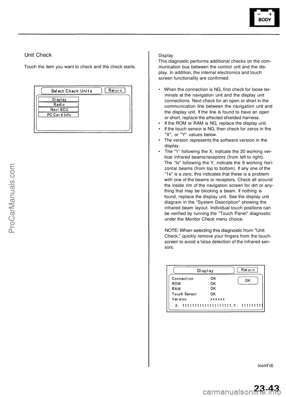
Unit Check
Touch the item you want to check and the check starts.
Display
This diagnostic performs additional checks on the com-
munication bus between the control unit and the dis-
play. In addition, the internal electronics and touch
screen functionality are confirmed.
• When the connection is NG, first check for loose ter-
minals at the navigation unit and the display unit
connections. Next check for an open or short in the
communication line between the navigation unit and
the display unit. If the line is found to have an open
or short, replace the affected shielded harness.
• If the ROM or RAM is NG, replace the display unit.
• If the touch sensor is NG, then check for zeros in the
"X", or "Y" values below.
• The version represents the software version in the
display.
• The "1" following the X, indicate the 20 working ver-
tical infrared beams/receptors (from left to right).
The "Is" following the Y, indicate the 9 working hori-
zontal beams (from top to bottom). If any one of the
"1s" is a zero, this indicates that these is a problem
with one of the beams or receptors. Check all around
the inside rim of the navigation screen for dirt or any-
thing that may be blocking a beam. If nothing is
found, replace the display unit. See the display unit
diagram in the "System Description" showing the
infrared beam layout. Individual touch positions can
be verified by running the "Touch Panel" diagnostic
under the Monitor Check menu choice.
NOTE: When selecting this diagnostic from "Unit
Check," quickly remove your fingers from the touch-
screen to avoid a false detection of the infrared sen-
sors.ProCarManuals.com
Page 374 of 1954
Engine Removal/Installatio n
Removal (cont'd )
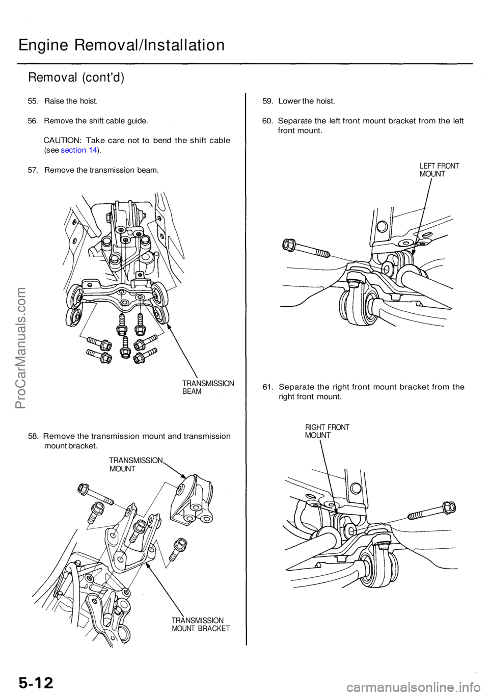
55. Rais e th e hoist .
56. Remov e th e shif t cabl e guide .
CAUTION : Tak e car e no t t o ben d th e shif t cabl e
(see sectio n 14 ).
57 . Remov e th e transmissio n beam .
TRANSMISSIO NBEAM
58. Remov e th e transmissio n moun t an d transmissio n
moun t bracket .
TRANSMISSION ,MOUNT
TRANSMISSIO NMOUNT BRACKE T
59. Lowe r th e hoist .
60 . Separat e th e lef t fron t moun t bracke t fro m th e lef t
fron t mount .
LEFT FRON TMOUNT
61. Separat e th e righ t fron t moun t bracke t fro m th e
righ t fron t mount .
RIGHT FRON TMOUNT
ProCarManuals.com
Page 378 of 1954
Engine Removal/Installatio n
Installation (cont'd )
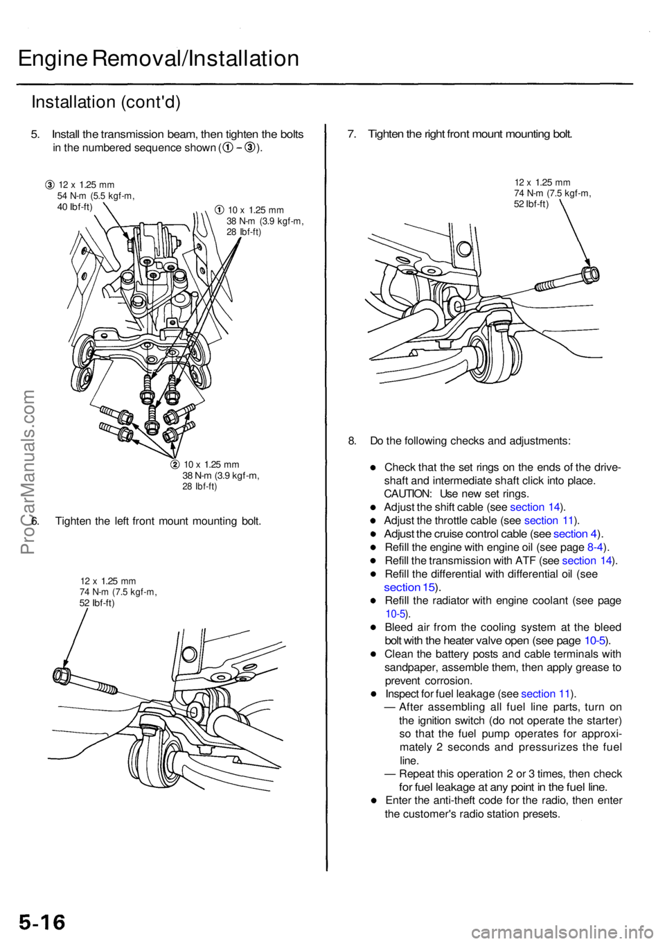
5. Instal l th e transmissio n beam , the n tighte n th e bolt s
in th e numbere d sequenc e show n ( ) .
12 x 1.2 5 mm54 N- m (5. 5 kgf-m ,40 Ibf-ft )10 x 1.2 5 mm38 N- m (3. 9 kgf-m ,28 Ibf-ft )
10 x 1.2 5 mm38 N- m (3. 9 kgf-m ,28 Ibf-ft )
6. Tighte n th e lef t fron t moun t mountin g bolt .
12 x 1.2 5 mm74 N- m (7. 5 kgf-m ,52 Ibf-ft )
7. Tighte n th e righ t fron t moun t mountin g bolt .
12 x 1.2 5 mm74 N- m (7. 5 kgf-m ,52 Ibf-ft )
8. D o th e followin g check s an d adjustments :
Chec k tha t th e se t ring s o n th e end s o f th e drive -
shaf t an d intermediat e shaf t clic k int o place .
CAUTION : Us e ne w se t rings .
Adjus t th e shif t cabl e (se e sectio n 14 ).
Adjus t th e throttl e cabl e (se e sectio n 11 ).
Adjus t th e cruis e contro l cabl e (se e sectio n 4 ).
Refil l th e engin e wit h engin e oi l (se e pag e 8-4 ).
Refil l th e transmissio n wit h AT F (se e sectio n 14 ).
Refil l th e differentia l wit h differentia l oi l (se e
sectio n 15 ).
Refil l th e radiato r wit h engin e coolan t (se e pag e
10-5).
Blee d ai r fro m th e coolin g syste m a t th e blee d
bolt wit h th e heate r valv e ope n (se e pag e 10-5 ).
Clea n th e batter y post s an d cabl e terminal s wit h
sandpaper , assembl e them , the n appl y greas e to
preven t corrosion .
Inspec t fo r fue l leakag e (se e sectio n 11 ).
— Afte r assemblin g al l fue l lin e parts , tur n o n
th e ignitio n switc h (d o no t operat e th e starter )
s o tha t th e fue l pum p operate s fo r approxi -
matel y 2 second s an d pressurize s th e fue l
line .
— Repea t thi s operatio n 2 or 3 times , the n chec k
for fue l leakag e a t an y poin t i n th e fue l line .
Ente r th e anti-thef t cod e fo r th e radio , the n ente r
th e customer' s radi o statio n presets .
ProCarManuals.com
Page 426 of 1954
Cylinder Heads
Installation (cont'd)
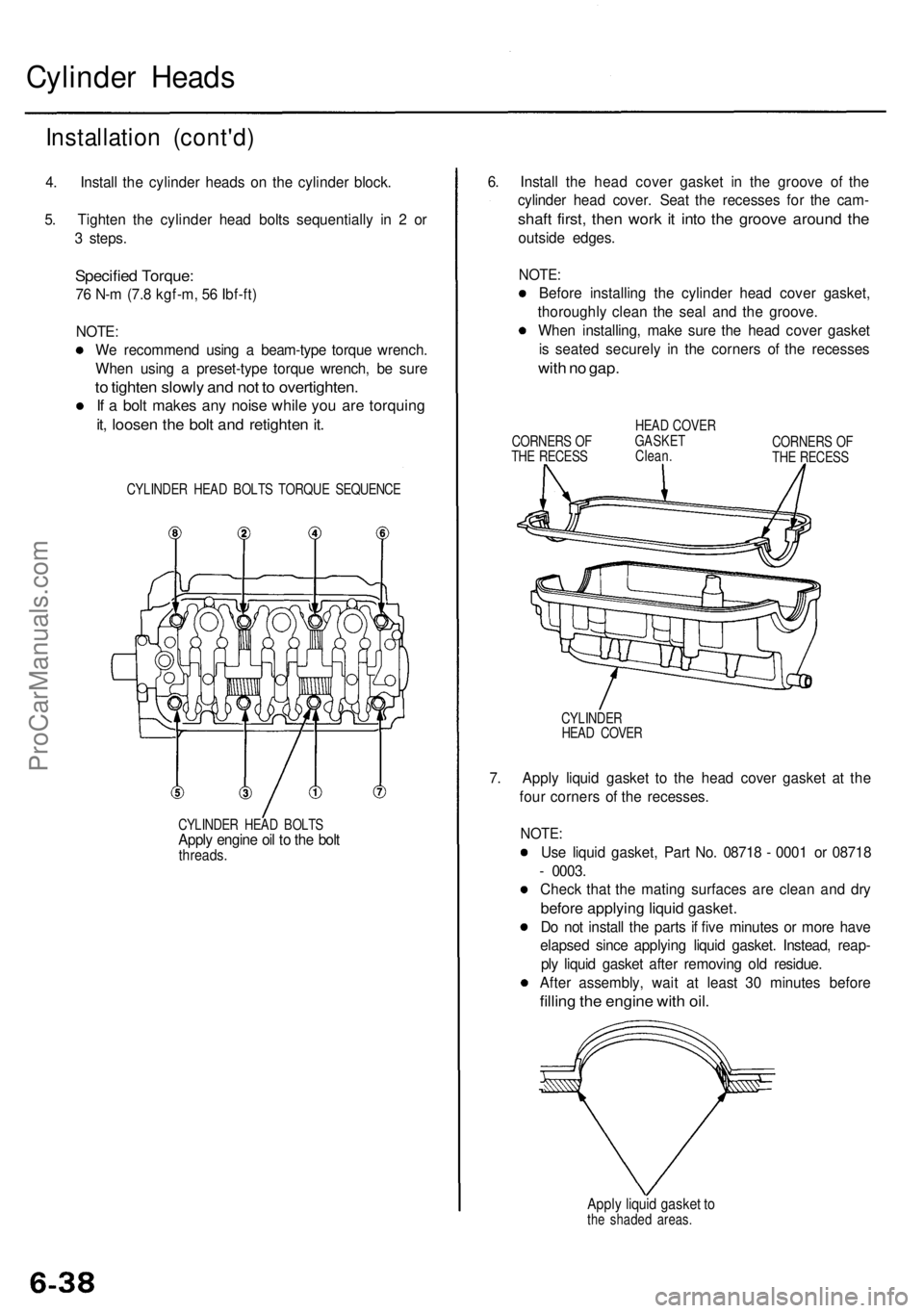
4. Install the cylinder heads on the cylinder block.
5. Tighten the cylinder head bolts sequentially in 2 or
3 steps.
Specified Torque:
76 N-m (7.8 kgf-m, 56 Ibf-ft)
NOTE:
We recommend using a beam-type torque wrench.
When using a preset-type torque wrench, be sure
to tighten slowly and not to overtighten.
If a bolt makes any noise while you are torquing
it, loosen the bolt and retighten it.
CYLINDER HEAD BOLTS TORQUE SEQUENCE
CYLINDER HEAD BOLTS
Apply engine oil to the bolt
threads.
6. Install the head cover gasket in the groove of the
cylinder head cover. Seat the recesses for the cam-
shaft first, then work it into the groove around the
outside edges.
NOTE:
Before installing the cylinder head cover gasket,
thoroughly clean the seal and the groove.
When installing, make sure the head cover gasket
is seated securely in the corners of the recesses
with no gap.
CORNERS OF
THE RECESS
HEAD COVER
GASKET
Clean.
CORNERS OF
THE RECESS
CYLINDER
HEAD COVER
7. Apply liquid gasket to the head cover gasket at the
four corners of the recesses.
NOTE:
Use liquid gasket, Part No. 08718 - 0001 or 08718
- 0003.
Check that the mating surfaces are clean and dry
before applying liquid gasket.
Do not install the parts if five minutes or more have
elapsed since applying liquid gasket. Instead, reap-
ply liquid gasket after removing old residue.
After assembly, wait at least 30 minutes before
filling the engine with oil.
Apply liquid gasket to
the shaded areas.ProCarManuals.com
Page 470 of 1954
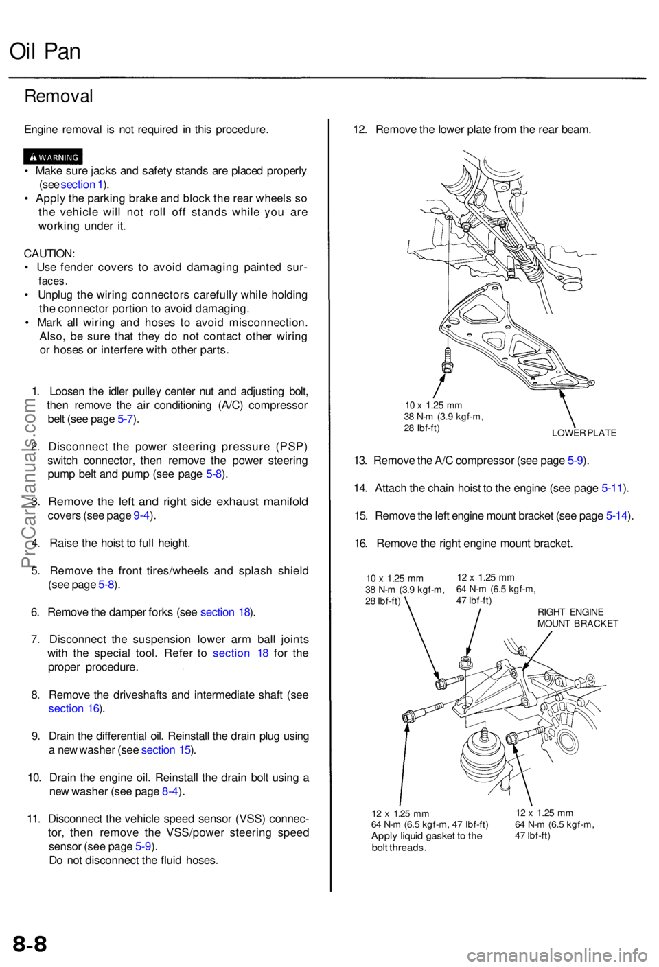
Oil Pa n
Remova l
Engine remova l i s no t require d i n thi s procedure .
• Mak e sur e jack s an d safet y stand s ar e place d properl y
(se e sectio n 1 ).
• Appl y th e parkin g brak e an d bloc k th e rea r wheel s s o
th e vehicl e wil l no t rol l of f stand s whil e yo u ar e
workin g unde r it .
CAUTION :
• Us e fende r cover s t o avoi d damagin g painte d sur -
faces .
• Unplu g th e wirin g connector s carefull y whil e holdin g
th e connecto r portio n to avoi d damaging .
• Mar k al l wirin g an d hose s t o avoi d misconnection .
Also , b e sur e tha t the y d o no t contac t othe r wirin g
o r hose s o r interfer e wit h othe r parts .
1 . Loose n th e idle r pulle y cente r nu t an d adjustin g bolt ,
the n remov e th e ai r conditionin g (A/C ) compresso r
bel t (se e pag e 5-7 ).
2 . Disconnec t th e powe r steerin g pressur e (PSP )
switc h connector , the n remov e th e powe r steerin g
pum p bel t an d pum p (se e pag e 5-8 ).
3 . Remov e th e lef t an d righ t sid e exhaus t manifol d
covers (se e pag e 9-4 ).
4 . Rais e th e hois t t o ful l height .
5 . Remov e th e fron t tires/wheel s an d splas h shiel d
(se e pag e 5-8 ).
6 . Remov e th e dampe r fork s (se e sectio n 18 ).
7 . Disconnec t th e suspensio n lowe r ar m bal l joint s
with the specia l tool . Refe r t o sectio n 1 8 fo r th e
prope r procedure .
8 . Remov e th e driveshaft s an d intermediat e shaf t (se e
sectio n 16 ).
9 . Drai n th e differentia l oil . Reinstal l th e drai n plu g usin g
a ne w washe r (se e sectio n 15 ).
10 . Drai n th e engin e oil . Reinstal l th e drai n bol t usin g a
ne w washe r (se e pag e 8-4 ).
11 . Disconnec t th e vehicl e spee d senso r (VSS ) connec -
tor , the n remov e th e VSS/powe r steerin g spee d
senso r (se e pag e 5-9 ).
D o no t disconnec t th e flui d hoses .
12 x 1.2 5 mm64 N- m (6. 5 kgf-m , 4 7 Ibf-ft )Apply liqui d gaske t t o th ebol t threads .
12 x 1.2 5 mm64 N- m (6. 5 kgf-m ,
4 7 Ibf-ft )
12. Remov e th e lowe r plat e fro m th e rea r beam .
LOWE R PLAT E
10 x 1.2 5 mm38 N- m (3. 9 kgf-m ,
2 8 Ibf-ft )
13. Remov e th e A/ C compresso r (se e pag e 5-9 ).
14 . Attac h th e chai n hois t t o th e engin e (se e pag e 5-11 ).
15 . Remov e th e lef t engin e moun t bracke t (se e pag e 5-14 ).
16 . Remov e th e righ t engin e moun t bracket .
10 x 1.2 5 mm38 N- m (3. 9 kgf-m ,
2 8 Ibf-ft )12 x 1.2 5 mm64 N- m (6. 5 kgf-m ,
4 7 Ibf-ft )
RIGHT ENGIN E
MOUN T BRACKE T
ProCarManuals.com
Page 798 of 1954
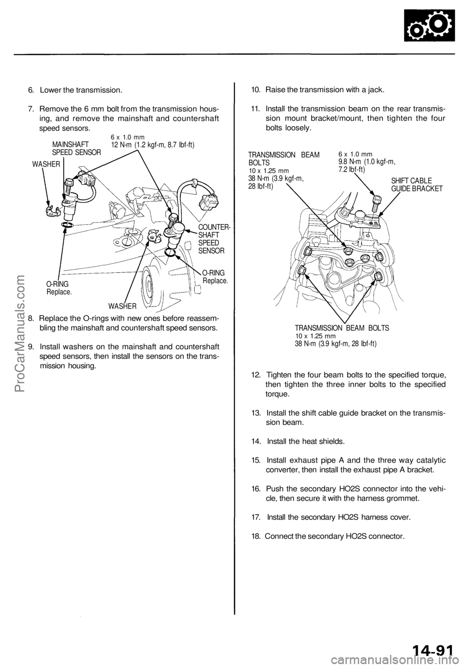
O-RING
Replace.
COUNTER-
SHAFT
SPEED
SENSOR
O-RING
Replace.
8. Replace the O-rings with new ones before reassem-
bling the mainshaft and countershaft speed sensors.
9. Install washers on the mainshaft and countershaft
speed sensors, then install the sensors on the trans-
mission housing.
10. Raise the transmission with a jack.
11. Install the transmission beam on the rear transmis-
sion mount bracket/mount, then tighten the four
bolts loosely.
TRANSMISSION BEAM
BOLTS
10 x
1.25
mm
38 N-m (3.9 kgf-m,
28 Ibf-ft)
6 x 1.0 mm
9.8 N-m (1.0 kgf-m,
7.2 Ibf-ft)
SHIFT CABLE
GUIDE BRACKET
TRANSMISSION BEAM BOLTS
10 x
1.25
mm
38 N-m (3.9 kgf-m, 28 Ibf-ft)
12. Tighten the four beam bolts to the specified torque,
then tighten the three inner bolts to the specified
torque.
13. Install the shift cable guide bracket on the transmis-
sion beam.
14. Install the heat shields.
15. Install exhaust pipe A and the three way catalytic
converter, then install the exhaust pipe A bracket.
16. Push the secondary HO2S connector into the vehi-
cle, then secure it with the harness grommet.
17. Install the secondary HO2S harness cover.
18. Connect the secondary HO2S connector.
6. Lower the transmission.
7. Remove the 6 mm bolt from the transmission hous-
ing, and remove the mainshaft and countershaft
speed sensors.
6 x 1.0 mm
12 N-m (1.2 kgf-m, 8.7 Ibf-ft)
MAINSHAFT
SPEED SENSOR
WASHER
WASHERProCarManuals.com
Page 825 of 1954
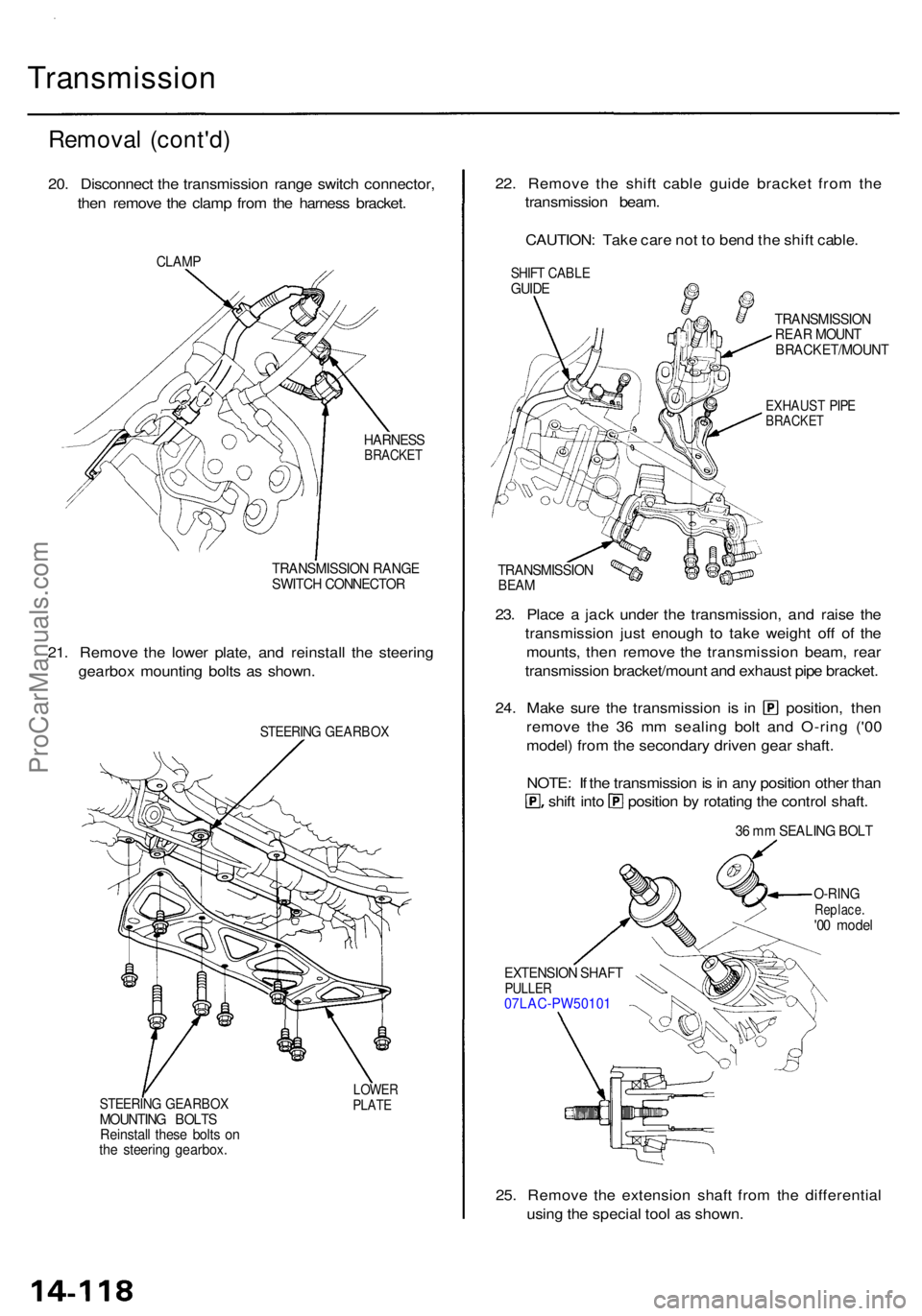
Transmission
Removal (cont'd )
20. Disconnec t th e transmissio n rang e switc h connector ,
the n remov e th e clam p fro m th e harnes s bracket .
CLAMP
HARNES SBRACKE T
TRANSMISSIO N RANG E
SWITC H CONNECTO R
21. Remov e th e lowe r plate , an d reinstal l th e steerin g
gearbo x mountin g bolt s a s shown .
STEERIN G GEARBO X
STEERING GEARBO XMOUNTING BOLT S
Reinstal l thes e bolt s o n
th e steerin g gearbox .
LOWERPLATE
22. Remov e th e shif t cabl e guid e bracke t fro m th e
transmissio n beam .
CAUTION : Tak e car e no t t o ben d th e shif t cable .
TRANSMISSIO N
REA R MOUN T
BRACKET/MOUN T
EXHAUST PIP EBRACKE T
TRANSMISSIO NBEAM
23. Plac e a jac k unde r th e transmission , an d rais e th e
transmissio n jus t enoug h t o tak e weigh t of f o f th e
mounts , the n remov e th e transmissio n beam , rea r
transmissio n bracket/moun t an d exhaus t pip e bracket .
24. Mak e sur e th e transmissio n i s i n position , the n
remov e th e 3 6 m m sealin g bol t an d O-rin g ('0 0
model ) fro m th e secondar y drive n gea r shaft .
NOTE : I f th e transmissio n is in an y positio n othe r tha n
shift int o positio n b y rotatin g th e contro l shaft .
36 m m SEALIN G BOL T
O-RIN GReplace .'00 mode l
EXTENSIO N SHAF T
PULLE R07LAC-PW5010 1
25. Remov e th e extensio n shaf t fro m th e differentia l
usin g th e specia l too l a s shown .
SHIFT CABL EGUIDE
ProCarManuals.com
Page 1020 of 1954
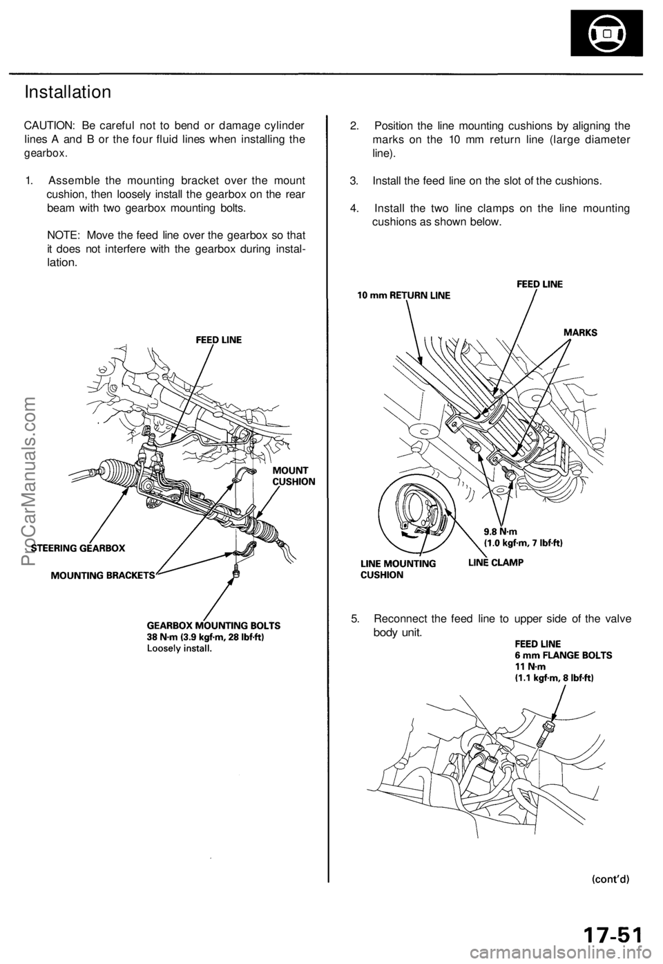
5. Reconnect the feed line to upper side of the valve
body unit.
2. Position the line mounting cushions by aligning the
marks on the 10 mm return line (large diameter
line).
3. Install the feed line on the slot of the cushions.
4. Install the two line clamps on the line mounting
cushions as shown below.
Installation
CAUTION: Be careful not to bend or damage cylinder
lines A and B or the four fluid lines when installing the
gearbox.
1. Assemble the mounting bracket over the mount
cushion, then loosely install the gearbox on the rear
beam with two gearbox mounting bolts.
NOTE: Move the feed line over the gearbox so that
it does not interfere with the gearbox during instal-
lation.ProCarManuals.com
Page 1043 of 1954
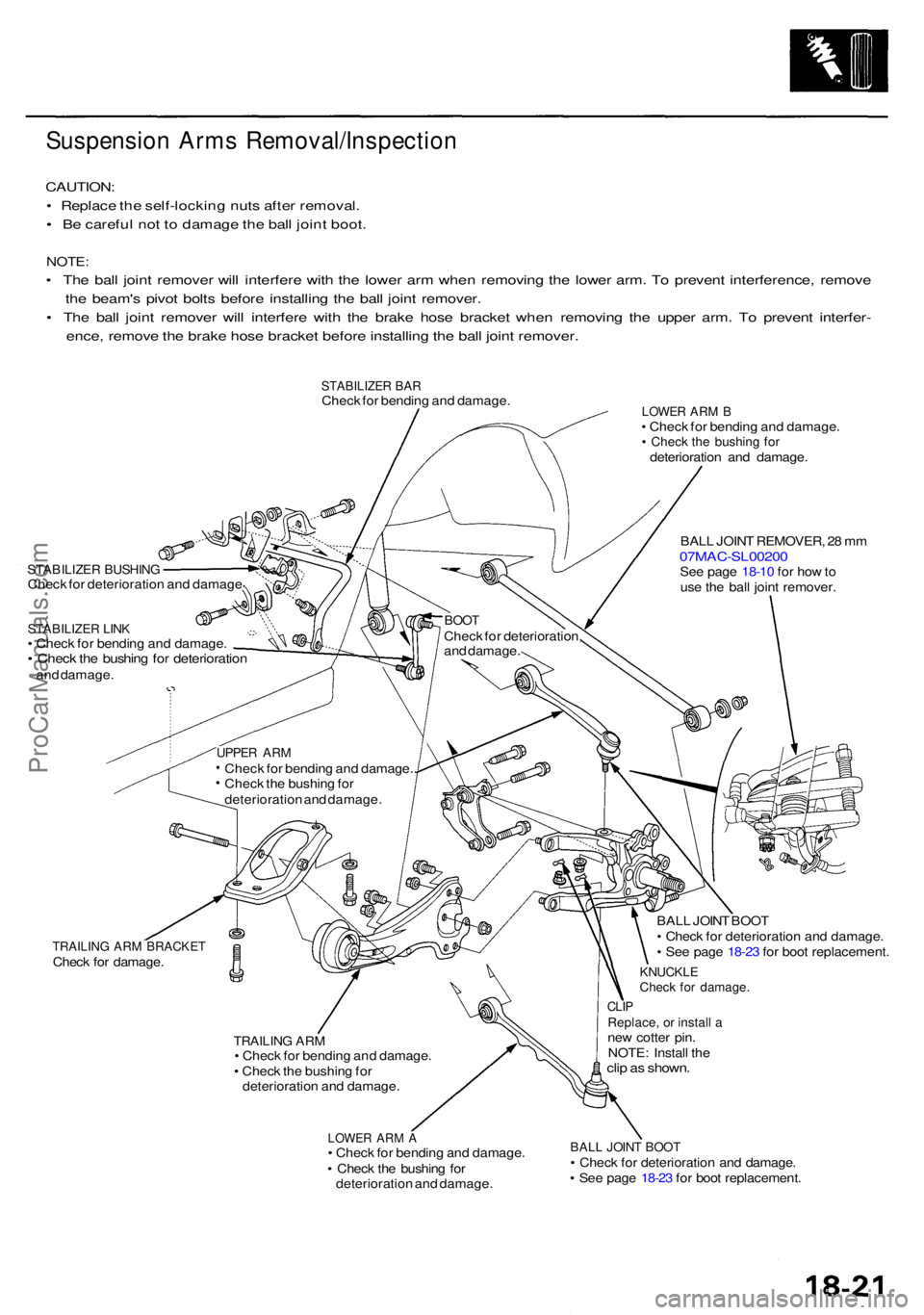
Suspension Arm s Removal/Inspectio n
CAUTION:
• Replac e th e self-lockin g nut s afte r removal .
• B e carefu l no t t o damag e th e bal l join t boot .
NOTE :
• Th e bal l join t remove r wil l interfer e wit h th e lowe r ar m whe n removin g th e lowe r arm . T o preven t interference , remov e
th e beam' s pivo t bolt s befor e installin g th e bal l join t remover .
• Th e bal l join t remove r wil l interfer e wit h th e brak e hos e bracke t whe n removin g th e uppe r arm . T o preven t interfer -
ence , remov e th e brak e hos e bracke t befor e installin g th e bal l join t remover .
STABILIZE R BA RChec k fo r bendin g an d damage .
STABILIZE R BUSHIN GCheck fo r deterioratio n an d damag e
STABILIZE R LIN K• Chec k fo r bendin g an d damage .• Chec k th e bushin g fo r deterioratio nand damage .
LOWER AR M B• Chec k fo r bendin g an d damage .• Chec k th e bushin g fo rdeterioratio n an d damage .
BAL L JOIN T REMOVER , 2 8 m m
07MAC-SL0020 0See pag e 18-1 0 fo r ho w to
us e th e bal l join t remover .
TRAILING AR M BRACKE TCheck fo r damage .
TRAILING AR M• Chec k fo r bendin g an d damage .
• Chec k th e bushin g fo r
deterioratio n an d damage .
LOWER AR M A• Chec k fo r bendin g an d damage .
• Chec k th e bushin g fo r
deterioratio n an d damage . BAL
L JOIN T BOO T
• Chec k fo r deterioratio n an d damage .
• Se e pag e 18-2 3 fo r boo t replacement .
KNUCKLECheck fo r damage .
CLIPReplace , o r instal l ane w cotte r pin .
NOTE : Instal l th e
clip a s shown .
BALL JOIN T BOO T• Chec k fo r deterioratio n an d damage .
• Se e pag e 18-2 3 fo r boo t replacement .
BOOTChec k fo r deterioration ,
an d damage .
UPPER AR MChec k fo r bendin g an d damage. .
Chec k th e bushin g fo r
deterioratio n an d damage .
ProCarManuals.com