water pump ACURA RL KA9 1996 Service Repair Manual
[x] Cancel search | Manufacturer: ACURA, Model Year: 1996, Model line: RL KA9, Model: ACURA RL KA9 1996Pages: 1954, PDF Size: 61.44 MB
Page 496 of 1954
Inspection
1. Remov e th e timin g bel t (se e pag e 6-8 ).
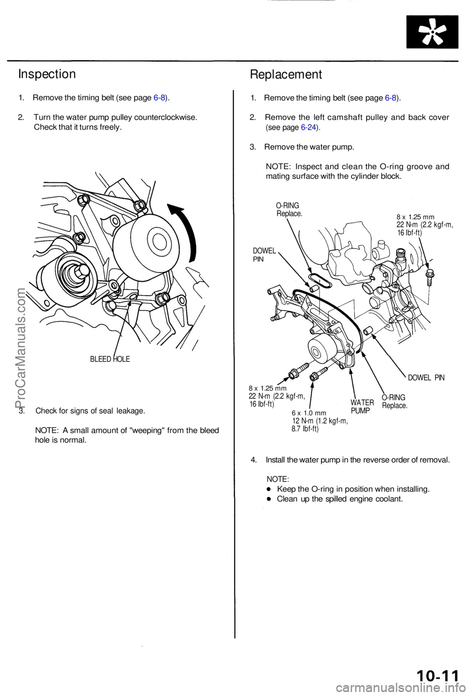
2 . Tur n th e wate r pum p pulle y counterclockwise .
Chec k tha t i t turn s freely .
BLEED HOL E
3. Chec k fo r sign s o f sea l leakage .
NOTE: A smal l amoun t o f "weeping " fro m th e blee d
hol e is normal .
Replacemen t
1. Remov e th e timin g bel t (se e pag e 6-8 ).
2 . Remov e th e lef t camshaf t pulle y an d bac k cove r
(see pag e 6-24 ).
3 . Remov e th e wate r pump .
NOTE : Inspec t an d clea n th e O-rin g groov e an d
matin g surfac e wit h th e cylinde r block .
O-RIN GReplace .8 x 1.2 5 mm22 N- m (2. 2 kgf-m ,
1 6 Ibf-ft )
DOWE LPIN
DOWE L PI N
8 x 1.2 5 mm22 N- m (2. 2 kgf-m ,
1 6 Ibf-ft )
6 x 1. 0 m m12 N- m (1. 2 kgf-m ,
8. 7 Ibf-ft )
4. Instal l th e wate r pum p in th e revers e orde r o f removal .
NOTE:
Keep th e O-rin g in positio n whe n installing .
Clea n u p th e spille d engin e coolant .
WATERPUMP
O-RIN GReplace .
ProCarManuals.com
Page 1054 of 1954
Inspection and Adjustment
Bleeding
CAUTION:
• Always use Genuine Honda DOT 3 Brake Fluid. Using
a non-Honda brake fluid can cause corrosion and
decrease the life of the system.
• Make sure no dirt or other foreign matter is allowed
to contaminate the brake fluid.
• Do not spill brake fluid on the vehicle, it may damage
the paint; if brake fluid does contact the paint, wash
it off immediately with water.
NOTE: The reservoir on the master cylinder must be at
the MAX (upper) level mark at the start of the bleeding
procedure and checked after bleeding each brake
caliper. Add fluid as required.
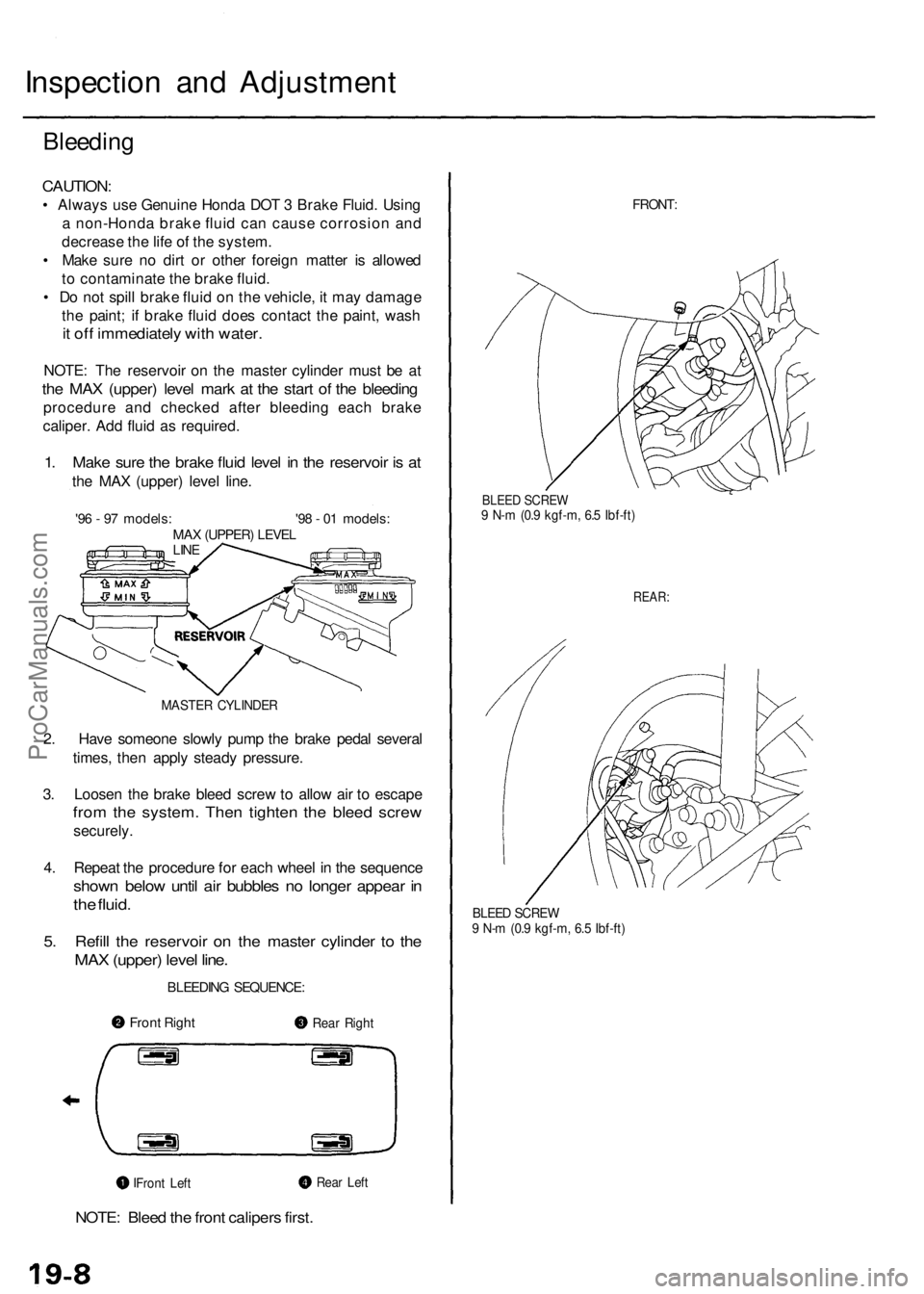
1. Make sure the brake fluid level in the reservoir is at
the MAX (upper) level line.
'96 - 97 models: '98 - 01 models:
MAX (UPPER) LEVEL
LINE
MASTER CYLINDER
2. Have someone slowly pump the brake pedal several
times, then apply steady pressure.
3. Loosen the brake bleed screw to allow air to escape
from the system. Then tighten the bleed screw
securely.
4. Repeat the procedure for each wheel in the sequence
shown below until air bubbles no longer appear in
the fluid.
5. Refill the reservoir on the master cylinder to the
MAX (upper) level line.
BLEEDING SEQUENCE:
NOTE: Bleed the front calipers first.
FRONT:
BLEED SCREW
9 N-m (0.9 kgf-m, 6.5 Ibf-ft)
REAR:
BLEED SCREW
9 N-m (0.9 kgf-m, 6.5 Ibf-ft)
Front Right
Rear Right
Rear Left
Front LeftProCarManuals.com
Page 1186 of 1954
Modulator Unit
Removal/Installation
NOTE:
Do not spill brake fluid on the vehicle; it may damage the paint; if brake fluid does not contact the paint, wash it off
immediately with water.
Take care not to damage or deform the brake lines during removal and installation.
To prevent the brake fluid from flowing, plug and cover the hose ends and joints with a shop towel or equivalent mate-
rial.
Removal
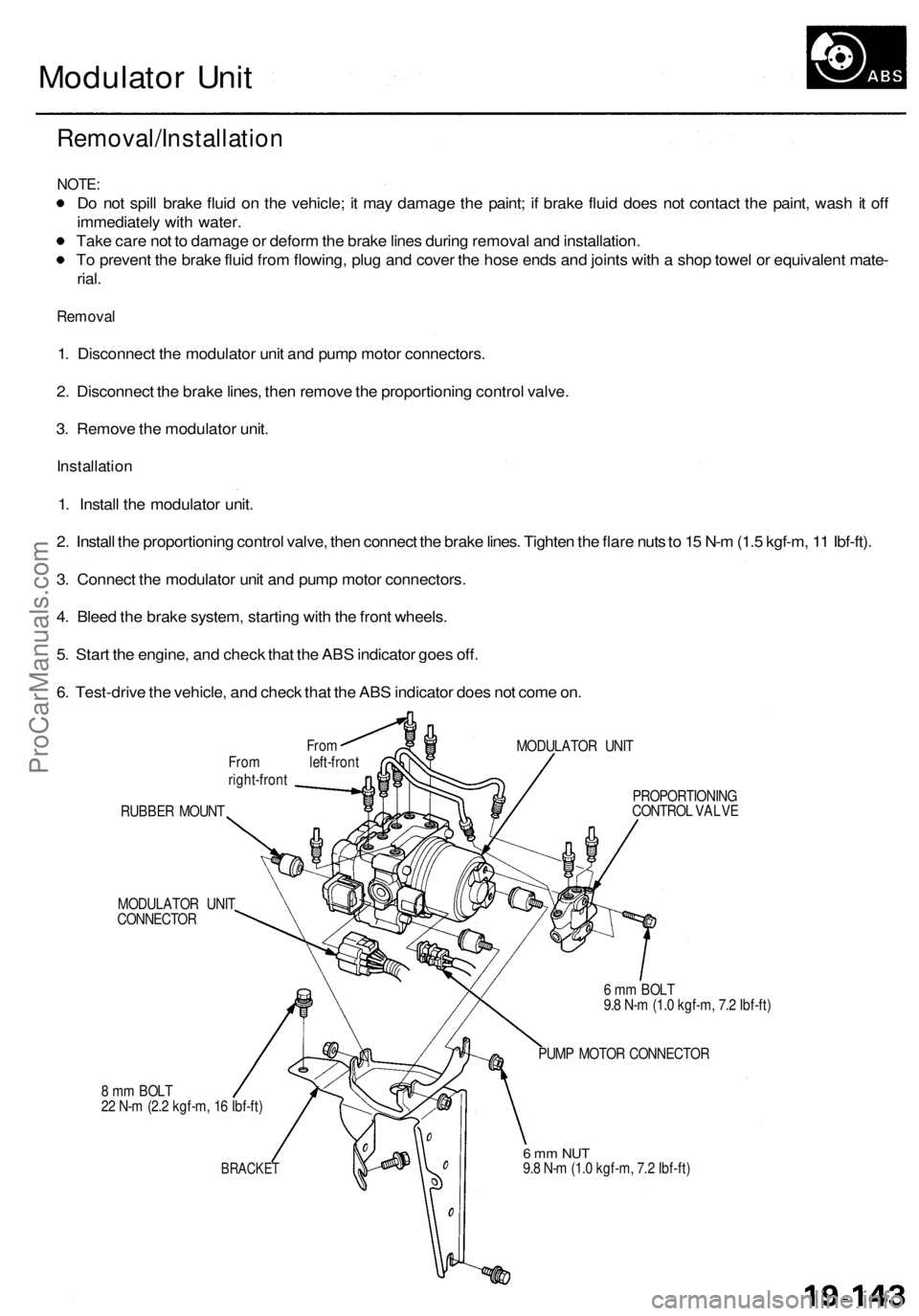
1. Disconnect the modulator unit and pump motor connectors.
2. Disconnect the brake lines, then remove the proportioning control valve.
3. Remove the modulator unit.
Installation
1. Install the modulator unit.
2. Install the proportioning control valve, then connect the brake lines. Tighten the flare nuts to 15 N-m (1.5 kgf-m, 11 Ibf-ft).
3. Connect the modulator unit and pump motor connectors.
4. Bleed the brake system, starting with the front wheels.
5. Start the engine, and check that the ABS indicator goes off.
6. Test-drive the vehicle, and check that the ABS indicator does not come on.
From
From left-front
right-front
MODULATOR UNIT
RUBBER MOUNT
MODULATOR UNIT
CONNECTOR
8 mm BOLT
22 N-m (2.2 kgf-m, 16 Ibf-ft)
BRACKET
PROPORTIONING
CONTROL VALVE
6 mm BOLT
9.8 N-m (1.0 kgf-m, 7.2 Ibf-ft)
PUMP MOTOR CONNECTOR
6 mm NUT
9.8 N-m (1.0 kgf-m, 7.2 Ibf-ft)ProCarManuals.com