Electrical Acura RSX 2006 Owner's Manual
[x] Cancel search | Manufacturer: ACURA, Model Year: 2006, Model line: RSX, Model: Acura RSX 2006Pages: 255, PDF Size: 3.41 MB
Page 23 of 255

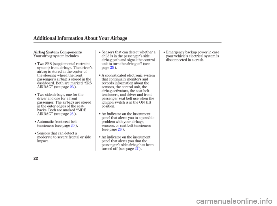
Your airbag system includes:Two side airbags, one f or the
driver and one f or a f ront
passenger. The airbags are stored
in the outer edges of the seat-
backs. Both are marked ‘‘SIDE
AIRBAG’’ (see page ).
Sensors that can detect a
moderate to severe frontal or side
impact. Automatic front seat belt
tensioners (see page ). Emergency backup power in case
your vehicle’s electrical system is
disconnected in a crash.
Sensors that can detect whether a
child is in the passenger’s side
airbag path and signal the control
unit to turn the airbag of f (see
page ).
A sophisticated electronic system
that continually monitors and
records inf ormation about the
sensors, the control unit, the
airbag activators, the seat belt
tensioners, and driver and f ront
passenger seat belt use when the
ignition switch is in the ON (II)
position.
An indicator on the instrument
panel that alerts you to a possible
problem with your airbags,
sensors, or seat belt tensioners
(see page ).
An indicator on the instrument
panel that alerts you that the
passenger’s side airbag has been
turned of f (see page ).
Two SRS (supplemental restraint
system) f ront airbags. The driver’s
airbag is stored in the center of
the steering wheel; the f ront
passenger’sairbagisstoredinthe
dashboard. Both are marked ‘‘SRS
AIRBAG’’ (see page ).
23
20
25
27
26
25
A irbag System Components
Additional Inf ormation About Your Airbags
22
Page 66 of 255

When you turn the ignition switch to
the ON (II) position, the immobilizer
system indicator should come on f or
a f ew seconds, then go out. If the
indicator starts to blink, it means the
system does not recognize the
coding of the key. Turn the ignition
switch to the LOCK (0) position,
remove the key, reinsert it, and turn
the ignition switch to the ON (II)
position again.If the system repeatedly does not
recognize the coding of your key,
contact your dealer.
Do not attempt to alter this system
or add other devices to it. Electrical
problems could result that may make
your vehicle undriveable.
If you lose your key and you cannot
start the engine, contact your dealer.
The immobilizer system protects
your vehicle f rom thef t. If an
improperly-coded key (or other
device) is used, the engine’s f uel
system is disabled.
The system may not recognize your
key’s coding if another immobilizer
key or other metal object (i.e. key
f ob) is near the ignition switch when
you insert the key.
As required by the FCC:
This device complies with Part 15 of theFCC rules. Operation is subject to thef ollowing two conditions: (1) This devicemay not cause harmf ul interf erence, and(2) this device must accept anyinterf erence received, includinginterf erence that may cause undesiredoperation.
Changes or modif ications not expresslyapproved by the party responsible f orcompliance could void the user’sauthority to operate the equipment.
This device complies with IndustryCanada Standard RSS-210.Operation is subject to the f ollowing twoconditions: (1) this device may not causeinterf erence, and (2) this device mustaccept any interf erence that may causeundesired operation of the device.
Immobilizer System
Inst rument s and Cont rols
65
Page 84 of 255

There are two accessory power
sockets, one is located in the f ront of
the center console. The other is
located at the rear of the console. To
use either power socket, pull up the
cover.These sockets are intended to supply
power f or 12 volt DC accessories
that are rated 120 watts or less (10
amps).
To power an accessory, the ignition
switch must be in the ACCESSORY
(I) or ON (II) position.
These sockets will not power an
automotive type cigarette lighter
element.
To open the beverage holder, push
the lef t knob and slide the cover
forward. Be caref ul when you are using the
beverage holders. Spilled liquid that
is very hot can scald you or your
passengers. Spilled liquids can also
damage the upholstery, carpeting,
and electrical components in the
interior.
U.S.: Standard on all models
Canada: Rear power socket optional
Interior Convenience Items
Beverage Holders Accessory Power Sockets
Inst rument s and Cont rols
83
Push
Page 125 of 255

Radio signals, especially on the FM
band, are def lected by large objects
such as buildings and hills. Your
radio then receives both the direct
signal f rom the station’s transmitter,
and the def lected signal. This causes
the sound to distort or flutter. This is
a main cause of poor radio reception
in city driving.Radio reception can be af f ected by
atmospheric conditions such as
thunderstorms, high humidity, and
even sunspots. You may be able to
receive a distant radio station one
day and not receive it the next day
because of a change in conditions.
Electrical interf erence f rom passing
vehicles and stationary sources can
cause temporary reception problems.
As required by the FCC:
Changes or modif ications not expresslyapproved by the party responsible f orcompliance could void the user’sauthority to operate the equipment.
Radio Reception
124
Page 126 of 255

If you make a mistake entering the
code, do not start over; complete the
f ive-digit sequence, then enter the
correct code. You have 10 tries to
enter the correct code. If you are
unsuccessf ul in 10 attempts, you
must then leave the system on for 1
hour bef ore trying again.
If thecodecardislost,yourdealer
can access your code with your
radio’s serial number. To access the
serial number, turn the radio on. Itmust display ‘‘COdE’’, then turn the
radio of f . Push the preset 1, preset 6,
and power buttons at the same time,
then quickly release.
You will have to store your favorite
stations in the preset buttons after
the system begins working. Your
original settings were lost when the
power was disconnected.
Your vehicle’s audio system will
disable itself if it is disconnected
f rom electrical power f or any reason.
To make it work again, you must
enter a specif ic f ive-digit code in the
preset buttons. Because there are
hundreds of number combinations
possible f rom f ive-digits, making the
system work without knowing the
exact code is nearly impossible.
Youshouldhavereceivedacardthat
lists your audio system’s code
number and serial number. It is best
tostorethiscardinasafeplaceat
home. In addition, you should write
the audio system’s serial number in
this owner’s manual. If you lose the
card, you must obtain the code
number f rom your dealer. To do this,
you will need the system’s serial
number. If your vehicle’s battery is
disconnected or goes dead, or the
radio f use is removed, the audio
system will disable itself . If this
happens, you will see ‘‘COdE’’ in the
frequencydisplaythenexttimeyou
turn on the system. Use the preset
buttons to enter the five-digit code.
The code is located on the radio code
card included in your owner’s
manual kit. When it is entered
correctly, the radio will start playing.
Theft Protection
Radio T hef t Protection
Features
125
Page 140 of 255

Your dealer has Acura accessories
that allow you to personalize your
vehicle. These accessories have
been designed and approved f or your
vehicle, and are covered by warranty. Modif ying your vehicle, or installing
some non-Acura accessories, can
make it unsaf e. Bef ore you make any
modif ications or add any accessories,
be sure to read the f ollowing
inf ormation.When properly installed, cellular
phones, alarms, two-way radios, and
low-powered audio systems should
not interf ere with your vehicle’s
computer controlled systems, such
as your airbags and anti-lock brakes.Bef ore installing any accessory:
Make sure the accessory does not
obscure any lights, or interf ere
with proper vehicle operation or
perf ormance.
Although non-Acura accessories may
f it on your vehicle, they may not
meet f actory specif ications, and
could adversely af f ect your vehicle’s
handling and stability. Be sure electronic accessories do
not overload electrical circuits
(see page ) or interf ere with
proper operation of your vehicle.
Bef ore installing any electronic
accessory, have the installer
contact your dealer for assistance.
If possible, have your dealer
inspect the f inal installation.
220
A ccessories
A ccessories and Modif ications
Bef ore Driving
139
Improper accessories or
modifications can affect your
vehicle’s handling, stability, and
performance, and cause a
crash in which you can be hurt
or killed.
Follow all instructions in this
owner’s manual regarding
accessories and modifications.
Page 148 of 255

Apply the parking brake.
In cold weather, turn of f all
electrical accessories to reduce
the drain on the battery.
Push the clutch pedal down all the
way.
Make sure the shif t lever is in
Park. Press on the brake pedal.
Without touching the accelerator
pedal, turn the ignition key to the
START (III) position. Do not hold
the key in the START (III)
position f or more than 15 seconds
at a time. If the engine does not
start right away, pause for at least
10 seconds bef ore trying again.If the engine does not start within
15 seconds, or starts but stalls
right away, repeat step 4 with the
accelerator pedal pressed halfway
down. If the engine starts, release
pressure on the accelerator pedal
so the engine does not race.
If the engine still does not start,
press the accelerator pedal all the
way down and hold it there while
starting in order to clear f looding.
If the engine still does not start,
return to step 5.
1.
2.
3.
4.
5.
6.
Manual Transmission:
Automatic Transmission: 65
Starting the Engine
Driving
147
T he immobilizer system protects your
vehicle f rom thef t. If an improperly-
coded key (or other device) is used, the
engine’s f uel system is disabled. For
more inf ormation, see page .
The engine is harder to start in cold
weather. Also, the thinner air f ound at
altitudes above 8,000 f eet (2,400
meters) adds to this problem.
Page 163 of 255

If you choose electric brakes, be
sure they are electrically actuated.
Do not attempt to tap into your
vehicle’s hydraulic system. No
matter how successf ul it may seem,
any attempt to attach trailer brakes
to your vehicle’s hydraulic system
will lower braking ef f ectiveness and
create a potential hazard.
Seeyourtrailerdealerformore
inf ormation on installing electric
brakes.
Trailer lights and equipment must
comply with f ederal, state, province,
and local regulations. Check with
local trailer sales or rental agencies
f or requirements f or the areas where
you plan to tow, and use only
equipment designed f or your vehicle.Since lighting and wiring vary by
trailer type and brand, you should
have a qualif ied technician install a
suitable connector between the
vehicle and the trailer. Improper
equipment or installation can cause
damage to your vehicle’s electrical
system and af f ect your vehicle
warranty.If you use a converter, you can get
the connector and pins that mate
with the connector in your vehicle
f rom your dealer.
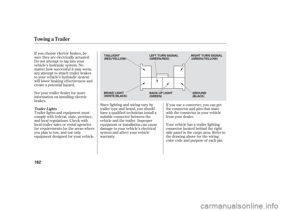
Your vehicle has a trailer lighting
connector located behind the right
side panel in the cargo area. Ref er to
thedrawingaboveforthewiring
color code and purpose of each pin.
Towing a Trailer
T railer L ights
162
TAILLIGHT
(RED/YELLOW)
LEFT TURN SIGNAL
(GREEN/RED)RIGHT TURN SIGNAL
(GREEN/YELLOW)
GROUND
(BLACK)
BACK UP LIGHT
(GREEN)
BRAKE LIGHT
(WHITE/BLACK)
Page 186 of 255

Install the rubber seal and make
sure it is right side up; it is marked
‘‘TOP.’’
Pull the battery back to its original
position, then install the bolt in the
hold-down, and tighten it securely. Push the electrical connector onto
the tabs of the new bulb. Make
sure it locks in place. Turn on the
headlights to test the new bulb.
Install the neck of the windshield
washer reservoir on the bracket.
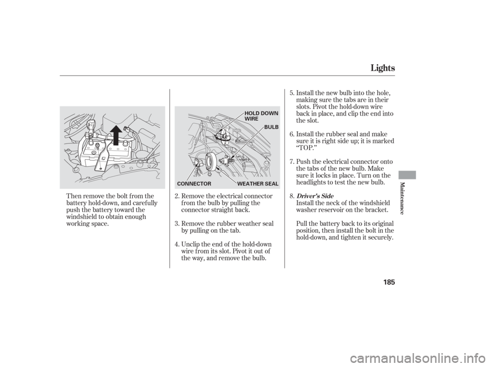
Then remove the bolt f rom the
battery hold-down, and caref ully
push the battery toward the
windshield to obtain enough
working space.
Unclip the end of the hold-down
wire f rom its slot. Pivot it out of
the way, and remove the bulb. Remove the rubber weather seal
by pulling on the tab. Remove the electrical connector
f rom the bulb by pulling the
connector straight back.Install the new bulb into the hole,
making sure the tabs are in their
slots. Pivot the hold-down wire
back in place, and clip the end into
the slot.
3.
4. 5.
6.
7.
8.
2.
Lights
Driver’s Side
Maint enance
185
HOLD DOWN
WIRE
BULB
WEATHER SEAL
CONNECTOR
Page 187 of 255

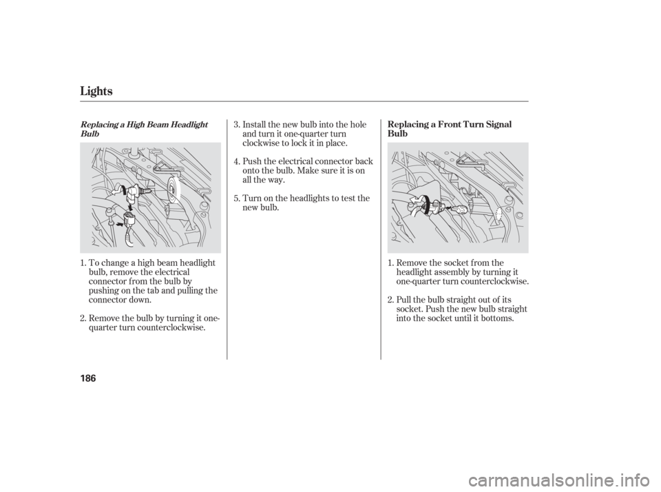
To change a high beam headlight
bulb, remove the electrical
connector f rom the bulb by
pushing on the tab and pulling the
connector down.
Remove the bulb by turning it one-
quarter turn counterclockwise.Push the electrical connector back
onto the bulb. Make sure it is on
all the way.
Turn on the headlights to test the
new bulb.
Remove the socket from the
headlight assembly by turning it
one-quarter turn counterclockwise.
Pull the bulb straight out of its
socket. Push the new bulb straight
into the socket until it bottoms.
Install the new bulb into the hole
and turn it one-quarter turn
clockwise to lock it in place.
3.
4.
5.
2. 1. 2. 1.
Lights
Replacing a Front T urn Signal
BulbReplacing a High Beam HeadlightBulb
186