lock Alfa Romeo 147 2007 Owner handbook (in English)
[x] Cancel search | Manufacturer: ALFA ROMEO, Model Year: 2007, Model line: 147, Model: Alfa Romeo 147 2007Pages: 291, PDF Size: 5.52 MB
Page 19 of 291
GETTING TO KNOW YOUR CAR
17
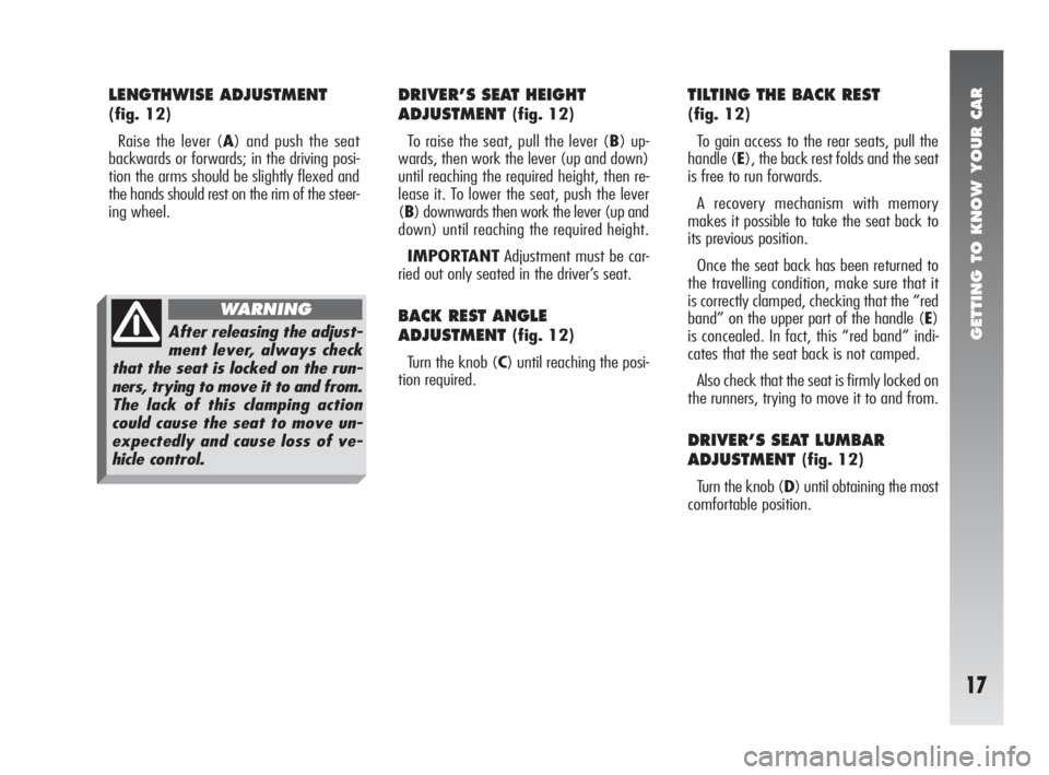
LENGTHWISE ADJUSTMENT
(fig. 12)
Raise the lever (A) and push the seat
backwards or forwards; in the driving posi-
tion the arms should be slightly flexed and
the hands should rest on the rim of the steer-
ing wheel.
DRIVER’S SEAT HEIGHT
ADJUSTMENT
(fig. 12)
To raise the seat, pull the lever (B) up-
wards, then work the lever (up and down)
until reaching the required height, then re-
lease it. To lower the seat, push the lever
(B) downwards then work the lever (up and
down) until reaching the required height.
IMPORTANTAdjustment must be car-
ried out only seated in the driver’s seat.
BACK REST ANGLE
ADJUSTMENT
(fig. 12)
Turn the knob (C) until reaching the posi-
tion required.
TILTING THE BACK REST
(fig. 12)
To gain access to the rear seats, pull the
handle (E), the back rest folds and the seat
is free to run forwards.
A recovery mechanism with memory
makes it possible to take the seat back to
its previous position.
Once the seat back has been returned to
the travelling condition, make sure that it
is correctly clamped, checking that the “red
band” on the upper part of the handle (E)
is concealed. In fact, this “red band” indi-
cates that the seat back is not camped.
Also check that the seat is firmly locked on
the runners, trying to move it to and from.
DRIVER’S SEAT LUMBAR
ADJUSTMENT
(fig. 12)
Turn the knob (D) until obtaining the most
comfortable position.
After releasing the adjust-
ment lever, always check
that the seat is locked on the run-
ners, trying to move it to and from.
The lack of this clamping action
could cause the seat to move un-
expectedly and cause loss of ve-
hicle control.
WARNING
Page 24 of 291
GETTING TO KNOW YOUR CAR
22
STEERING WHEEL
ADJUSTMENTS
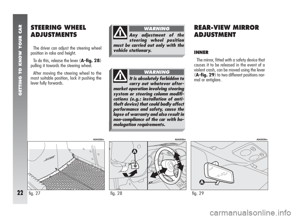
The driver can adjust the steering wheel
position in rake and height.
To do this, release the lever (A-fig. 28)
pulling it towards the steering wheel.
After moving the steering wheel to the
most suitable position, lock it pushing the
lever fully forwards.
REAR-VIEW MIRROR
ADJUSTMENT
INNER
The mirror, fitted with a safety device that
causes it to be released in the event of a
violent crash, can be moved using the lever
(A-fig. 29) to two different positions nor-
mal or antiglare.
fig. 27
A0A0328m
fig. 28
A0A0038m
fig. 29
A0A0039m
Any adjustment of the
steering wheel position
must be carried out only with the
vehicle stationary.
WARNING
It is absolutely forbidden to
carry out whatever after-
market operation involving steering
system or steering column modifi-
cations (e.g.: installation of anti-
theft device) that could badly affect
performance and safety, cause the
lapse of warranty and also result in
non-compliance of the car with ho-
mologation requirements.
WARNING
Page 25 of 291

GETTING TO KNOW YOUR CAR
23
Folding(fig. 31)
– In the event of need (for example when
the mirror causes difficulty in narrow spaces)
it is possible to fold the mirror moving it from
position (A) to position (B).Defrosting/demisting(fig. 32)
The electric mirrors are fitted with heat-
ing coils which come into operation with
rearscreen heating pressing the button (A)
thereby defrosting and/or demisting the mir-
rors.
IMPORTANTThe function is timed and
automatically switched off after a few min-
utes.
fig. 31
A0A0041m
fig. 32
A0A0486m
OUTER
Electric adjustment (fig. 30)
– use the switch (A) to select the mirror
required (right or left);
– pressing the button (B), in one of the
four directions, move the mirror selected pre-
viously;
– Position the switch (A) in the interme-
diate locking position.
IMPORTANTAdjustment is possible on-
ly with the ignition key at MAR.
fig. 30
A0A0040m
When driving the mirrors
should always be in posi-
tion (A).
WARNING
As the driver’s wing mirror
is curved, it may slightly
alter the perception of distance.
WARNING
Page 27 of 291

GETTING TO KNOW YOUR CAR
25
Do not keep the button
pressed when the window
is completely raised or
lowered.
IMPORTANTAfter locking the doors,
keeping the corresponding button of the re-
mote control pressed for about 2 seconds
causes automatic closing of the windows
and sunroof (if present). The remote control
button should be pressed until the windows
have completed their stroke; releasing the
button sooner, the windows stop in the po-
sition they are in at that moment.
On all versions, after unlocking the doors,
keeping the remote control button pressed
for about 2 seconds the windows and sun-
roof (if present) are opened.SEAT BELTS
USING THE SEAT BELTS
The belt should be worn keeping the chest
straight and rested against the seat back.
Take hold the tongue (A-fig. 35) and in-
sert it into the buckle (B), until hearing the
locking click.
At removal, if it jams, let it rewind for a
short stretch, then pull it out again without
jerking.
fig. 35
A0A0045m
Improper use of power
windows can be danger-
ous. Before and during use, always
make sure that the passengers are
not exposed to the risk of harm ei-
ther directly by the moving win-
dows or by personal objects drawn
or knocked by them. When leaving
the car, always remove the ignition
key to prevent the power windows
from being operated inadvertent-
ly, and harming anyone left on
board.
WARNING
Page 28 of 291

GETTING TO KNOW YOUR CAR
26
The rear seat is fitted with inertial seat belts
with three anchor points with reel for the
side seats and for the centre seat (fig. 36).
Through the reel, the belt automatically
adapts to the body of the passenger wear-
ing it, allowing freedom of movement.
When the car is parked on a steep slope
the reel mechanism may block; this is nor-
mal. The reel mechanism prevents the web-
bing coming out when it is jerked or if the
car brakes sharply, in a collision or when cor-
nering at high speed.To unfasten the seat belts, press button
(C). Guide the seat belt with your hand while
it is rewinding, to prevent it from twisting.
fig. 36
A0A0386m
Never press button (C)
when travelling.
WARNING
fig. 36a
A0A0708m
When the seat back is cou-
pled properly, the “red
band” (B) next to the seat back
levers (A) disappears. The “red
band” actually indicates improper
seat back coupling (fig. 36a). When
resetting it in proper position,
make sure to hear the locking click.
WARNING
After tilting, when reset-
ting the rear seat in
straight position, take care to repo-
sition the seat belt properly to
have it ready for use.
WARNING
Make sure the seat back is
correctly hooked on both
sides (not visible “red bands” (B))
to prevent seat back being thrown
forwards and injuring passengers
should you brake sharply.
WARNING
Page 29 of 291
GETTING TO KNOW YOUR CAR
27
FRONT SEAT BELT HEIGHT
ADJUSTMENT
The front seat belt ring can take different
positions which make it possible to adjust
the height of the belts.
Always adjust the height of the belts adapt-
ing it to the person who is wearing it. This
precaution improves their effectiveness. sub-
stantially reducing the risk of injury in the
event of a crash.
Correct adjustment is obtained when the
belt passes half way between the end of the
shoulder and the neck.
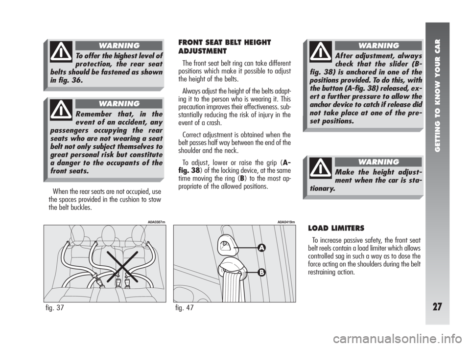
To adjust, lower or raise the grip (A-
fig. 38) of the locking device, at the same
time moving the ring (B) to the most ap-
propriate of the allowed positions.
LOAD LIMITERS
To increase passive safety, the front seat
belt reels contain a load limiter which allows
controlled sag in such a way as to dose the
force acting on the shoulders during the belt
restraining action.
fig. 47
A0A0419m
When the rear seats are not occupied, use
the spaces provided in the cushion to stow
the belt buckles.
fig. 37
A0A0387m
To offer the highest level of
protection, the rear seat
belts should be fastened as shown
in fig. 36.
WARNING
Remember that, in the
event of an accident, any
passengers occupying the rear
seats who are not wearing a seat
belt not only subject themselves to
great personal risk but constitute
a danger to the occupants of the
front seats.
WARNING
After adjustment, always
check that the slider (B-
fig. 38) is anchored in one of the
positions provided. To do this, with
the button (A-fig. 38) released, ex-
ert a further pressure to allow the
anchor device to catch if release did
not take place at one of the pre-
set positions.
WARNING
Make the height adjust-
ment when the car is sta-
tionary.
WARNING
Page 30 of 291

GETTING TO KNOW YOUR CAR
28
PRE-TENSIONING DEVICES
To increase the efficiency of the front seat
belts,Alfa 147 GTAis fitted with pre-
tensioning devices.
These devices “feel” that the car is being
subject to a violent impact by way of a sen-
sor rewind the seat belts a few centimetres.
In this way they ensure that the seat belt
adheres to the wearer before the restraining
action begins.
The seat belt locks to indicate that the de-
vice has intervened; the seat belt cannot be
drawn back up even when guiding it man-
ually.IMPORTANTThe pretensioner will give
maximum protection when the seat belt ad-
heres snugly to wearer’s chest and hips.
Front seat pretensioners activate only if
front seat belts are properly fitted into buck-
les.
A small amount of smoke may be pro-
duced. This smoke is in no way toxic and
presents no fire hazard.
The emergency tensioning retractor needs
no maintenance or lubrication. Any modifi-
cation to its original features will nullify the
retractor’s effectiveness. If, due to unusual
natural events (floods, high waves, etc.),
the device has been affected by water and
mud, it must be replaced.Operations involving
banging, vibrations or
heating (above 100°C for
a maximum of 6 hours) in the area
of the pretensioners may damage
or trigger off the device. Vibrations
from rough road surfaces or acci-
dental jolting caused by mounting
pavements etc. do not have any ef-
fect on the pretensioner. If, how-
ever, you need assistance, go to Al-
fa Romeo Authorized Services.The pretensioner can only
be used once. After a col-
lision that has triggered it, have it
replaced at Alfa Romeo Authorized
Service. The validity of the device
is written on the plate located on
the front left door near the lock.
Contact Alfa Romeo Authorized
Services to have pretensioner re-
placed as this date approaches.
WARNING
Page 41 of 291

GETTING TO KNOW YOUR CAR
39
IMPORTANTIn the event of side crash,
you can obtain the best protection by the
system keeping a correct position on the
seat, thus allowing correct window bag un-
folding.
IMPORTANTThe front and/or side air
bags may be activated if the car is subjected
to heavy shocks or accidents that involve the
underbody area, such as for example violent
bumps against steps, pavements or fixed ob-
stacles on the ground, falling into big holes
or bumpy roads.IMPORTANTThe triggering of air bags
releases a small amount of powder. This pow-
der is not harmful and does not indicate a
start of fire; also the surfaces of the deployed
bag and the car interior may be covered with
dusty residue: this may irritate the skin and
eyes. In the event of exposure, wash with
neutral soap and water.
The airbag system has a validity of 14
years for the pyrotechnic charge and 10
years for the coil contact (see the plate lo-
cated on the front left door near the lock).
Contact Alfa Romeo Authorized Services for
replacement as these dates approach.
IMPORTANTIf an accident has trig-
gered the air bag, Alfa Romeo Authorized
Services must be contacted to have the de-
vices activated replaced and to have the
whole system checked.All operations involving checking, repair-
ing and replacing components concerning
the Air bag must be carried out by Alfa
Romeo Authorized Services.
If the car is to be demolished, Alfa Romeo
Authorized Services should be contacted be-
forehand to have the system deactivated.
If the car changes ownership, the new
owner must be informed of the instructions
for use and of the above warnings and be
given this “Owner’s Manual“.
IMPORTANTThe triggering of the pre-
tensioners, front air bags and side bags is
decided by the electronic control unit in a
differentiated manner depending on the type
of crash. The failure to trigger one or more
of them does not necessarily indicate a sys-
tem malfunction.
Never rest head, arms and
elbows on the door, on the
windows and in the window bag
area to prevent possible injuries
during the inflation phase.
WARNING
Never lean head, arms and
elbows out of the window.
WARNING
Page 52 of 291
GETTING TO KNOW YOUR CAR
50
DASHBOARD
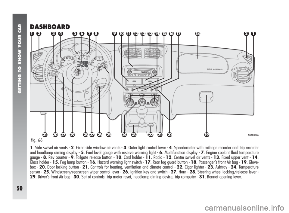
1. Side swivel air vents - 2. Fixed side window air vents - 3. Outer light control lever - 4. Speedometer with mileage recorder and trip recorder
and headlamp aiming display - 5. Fuel level gauge with reserve warning light - 6. Multifunction display - 7. Engine coolant fluid temperature
gauge - 8. Rev counter - 9. Tailgate release button - 10. Card holder - 11. Radio - 12. Centre swivel air vents - 13. Fixed upper vent - 14.
Glass holder - 15. Fog lamp button - 16. Hazard warning light switch - 17. Rear fog guard button - 18. Passenger’s front Air bag - 19. Glove-
box - 20. Door locking button - 21. Controls for heating, ventilation and climate control - 22. Cigar lighter - 23. Ashtray - 24. Temperature
sensor - 25. Windscreen/rearscreen wiper control lever - 26. Ignition key and switch - 27. Horn - 28. Steering wheel locking/release lever -
29. Driver’s front Air bag - 30. Set of controls: trip meter reset, headlamp aiming device, trip computer - 31. Bonnet opening lever. fig. 66
A0A0426m
Page 55 of 291
GETTING TO KNOW YOUR CAR
53
RECONFIGURABLE MULTIFUNCTION DISPLAY
The reconfigurable multifunction display is
able to display all the useful and necessary
information when driving and a menu allows
the following adjustments and/or settings:
TIME
DATE
OUTSIDE TEMPERATURE
INFORMATION ABOUT VEHICLE CONDITION
- Trip computer
- Lighting adjustment (rheostat)
- Display of failure messages with corre-
sponding symbol
- Display of warning messages with cor-
responding symbol (e.g.: possible ice on
road)Reconfigurable multifunction
display menu
SPEED
- Activation/deactivation of the corre-
sponding indication (ON/OFF)
- Setting the speed limit
TRIP B
- Activation/deactivation of the corre-
sponding function (ON/OFF)
TIME
- Setting the hours
- Setting the minutes
DATE
- Setting the day
- Setting the month
- Setting the year
DST (SUMMER TIME)
- Activation/deactivation of summer time
MODE 12/24
- Selecting the clock mode on 12 or 24
hours
RADIO
- Activation/deactivation of the following
items on the display:
frequency or RDS message of the radio
station selected, compact disc and cor-
responding track selected, cassette func-
tion onTELEPHONE
- Activation/deactivation of the following
items on the display: incoming or out-
going phone call with name and/or
number of the subscriber connected
NAVIGATION
- Activation/deactivation of the displays
and information concerning the route to
be followed
LANGUAGE
- Setting the language of the messages
shown on the display
UNITS
- Selection of the following units of mea-
sure: km, mi, °C, °F, km/l, l/100km,
mpg
BUZZER
- Buzzer volume adjustment
SERVICE
- Display of information concerning correct
vehicle maintenance, strictly connected
with the Scheduled Maintenance Pro-
gramme
MENU OFF
- Exits the menu.