open Alfa Romeo 147 2010 Owner handbook (in English)
[x] Cancel search | Manufacturer: ALFA ROMEO, Model Year: 2010, Model line: 147, Model: Alfa Romeo 147 2010Pages: 291, PDF Size: 5.52 MB
Page 206 of 291
IN AN EMERGENCY
204
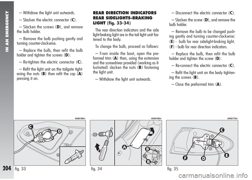
– Withdraw the light unit outwards.
– Slacken the electric connector (C).
– Slacken the screws (D), and remove
the bulb holder.
– Remove the bulb pushing gently and
turning counter-clockwise.
– Replace the bulb, then refit the bulb
holder and tighten the screws (D).
– Re-tighten the electric connector (C).
– Refit the light unit on the tailgate tight-
ening the nuts (B) then refit the cap (A)
pressing it on.REAR DIRECTION INDICATORS
REAR SIDELIGHTS-BRAKING
LIGHT
(fig. 33-34)
The rear direction indicators and the side
light-braking light are in the tail light unit fas-
tened to the body.
To change the bulb, proceed as follows:
– From inside the boot, open the pre-
formed trim (A) then, using the extension
and the screwdriver provided (working as il-
lustrated) slacken the nuts (B) fastening
the light unit.
– Withdraw the light unit outwards.– Disconnect the electric connector (C).
– Slacken the screw (D), and remove the
bulb holder.
– Remove the bulb to be changed push-
ing gently and turning counter-clockwise:
(E) - bulb for rear sidelight-braking light.
(F) - bulb for rear direction indicators.
– Replace the bulb, then refit the bulb
holder and tighten the screw (D).
– Re-connect the electric connector (C).
– Refit the light unit on the body tighten-
ing the screws (B).
– Close the preformed trim (A).
fig. 35
A0A0170m
fig. 34
A0A0169m
fig. 33
A0A0168m
Page 207 of 291
IN AN EMERGENCY
205
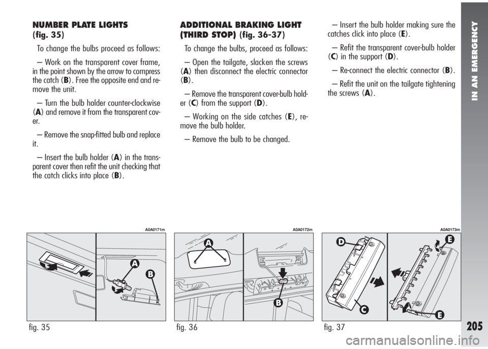
NUMBER PLATE LIGHTS
(fig. 35)
To change the bulbs proceed as follows:
– Work on the transparent cover frame,
in the point shown by the arrow to compress
the catch (B). Free the opposite end and re-
move the unit.
– Turn the bulb holder counter-clockwise
(A) and remove it from the transparent cov-
er.
– Remove the snap-fitted bulb and replace
it.
– Insert the bulb holder (A) in the trans-
parent cover then refit the unit checking that
the catch clicks into place (B).
ADDITIONAL BRAKING LIGHT
(THIRD STOP)
(fig. 36-37)
To change the bulbs, proceed as follows:
– Open the tailgate, slacken the screws
(A) then disconnect the electric connector
(B).
– Remove the transparent cover-bulb hold-
er (C) from the support (D).
– Working on the side catches (E), re-
move the bulb holder.
– Remove the bulb to be changed.– Insert the bulb holder making sure the
catches click into place (E).
– Refit the transparent cover-bulb holder
(C) in the support (D).
– Re-connect the electric connector (B).
– Refit the unit on the tailgate tightening
the screws (A).
fig. 37
A0A0173m
fig. 35
A0A0171m
fig. 36
A0A0172m
Page 208 of 291
IN AN EMERGENCY
206
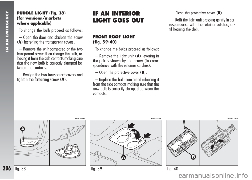
PUDDLE LIGHT (fig. 38)
(for versions/markets
where applicable)
To change the bulb proceed as follows:
– Open the door and slacken the screw
(A) fastening the transparent covers.
– Remove the unit composed of the two
transparent covers then change the bulb, re-
leasing it from the side contacts making sure
that the new bulb is correctly clamped be-
tween the contacts.
– Realign the two transparent covers and
tighten the fastening screw (A).IF AN INTERIOR
LIGHT GOES OUT
FRONT ROOF LIGHT
(fig. 39-40)
To change the bulbs proceed as follows:
– Remove the light unit (A) levering in
the points shown by the arrow (in corre-
spondence with the retainer catches).
– Open the protective cover (B).
– Replace the bulb concerned releasing it
from the side contacts making sure that the
new bulb is correctly clamped between the
contacts.– Close the protective cover (B).
– Refit the light unit pressing gently in cor-
respondence with the retainer catches, un-
til hearing the click.
fig. 40
A0A0176m
fig. 39
A0A0175m
fig. 38
A0A0174m
Page 209 of 291
IN AN EMERGENCY
207
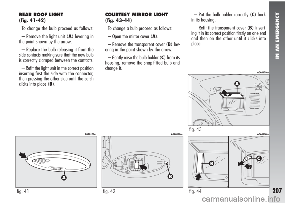
REAR ROOF LIGHT
(fig. 41-42)
To change the bulb proceed as follows:
– Remove the light unit (A) levering in
the point shown by the arrow.
– Replace the bulb releasing it from the
side contacts making sure that the new bulb
is correctly clamped between the contacts.
– Refit the light unit in the correct position
inserting first the side with the connector,
then pressing the other side until the catch
clicks into place (B).
COURTESY MIRROR LIGHT
(fig. 43-44)
To change a bulb proceed as follows:
– Open the mirror cover (A).
– Remove the transparent cover (B) lev-
ering in the point shown by the arrow.
– Gently raise the bulb holder (C) from its
housing, remove the snap-fitted bulb and
change it.– Put the bulb holder correctly (C) back
in its housing.
– Refit the transparent cover (B) insert-
ing it in its correct position firstly on one end
and then on the other until it clicks into
place.
fig. 41
A0A0177m
fig. 42
A0A0178mfig. 43
A0A0179m
fig. 44
A0A0180m
Page 210 of 291
IN AN EMERGENCY
208
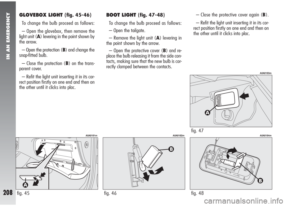
GLOVEBOX LIGHT (fig. 45-46)
To change the bulb proceed as follows:
– Open the glovebox, then remove the
light unit (A) levering in the point shown by
the arrow.
– Open the protection (B) and change the
snap-fitted bulb.
– Close the protection (B) on the trans-
parent cover.
– Refit the light unit inserting it in its cor-
rect position firstly on one end and then on
the other until it clicks into plac.BOOT LIGHT (fig. 47-48)
To change the bulb proceed as follows:
– Open the tailgate.
– Remove the light unit (A) levering in
the point shown by the arrow.
– Open the protective cover (B) and re-
place the bulb releasing it from the side con-
tacts, making sure that the new bulb is cor-
rectly clamped between the contacts.– Close the protective cover again (B).
– Refit the light unit inserting it in its cor-
rect position firstly on one end and then on
the other until it clicks into plac.
fig. 45
A0A0181m
fig. 46
A0A0182mfig. 47
A0A0183m
fig. 48
A0A0184m
Page 212 of 291
IN AN EMERGENCY
210
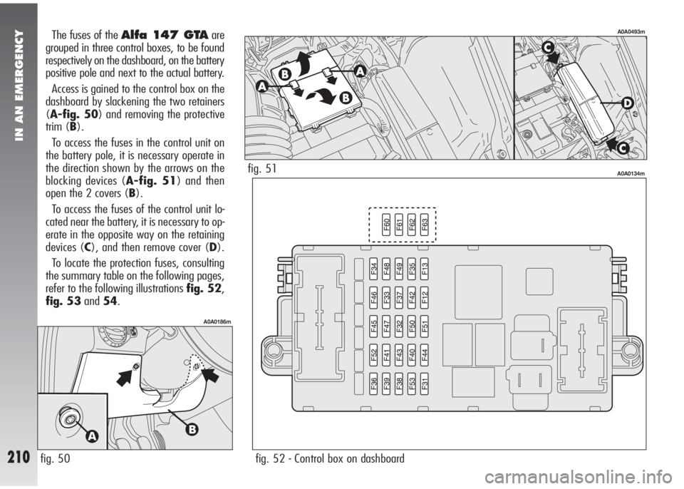
The fuses of the Alfa 147 GTAare
grouped in three control boxes, to be found
respectively on the dashboard, on the battery
positive pole and next to the actual battery.
Access is gained to the control box on the
dashboard by slackening the two retainers
(A-fig. 50) and removing the protective
trim (B).
To access the fuses in the control unit on
the battery pole, it is necessary operate in
the direction shown by the arrows on the
blocking devices (A-fig. 51) and then
open the 2 covers (B).
To access the fuses of the control unit lo-
cated near the battery, it is necessary to op-
erate in the opposite way on the retaining
devices (C), and then remove cover (D).
To locate the protection fuses, consulting
the summary table on the following pages,
refer to the following illustrations fig. 52,
fig. 53and54.
fig. 50
A0A0186m
fig. 52 - Control box on dashboard
A0A0134mfig. 51
A0A0493m
Page 233 of 291
VEHICLE MAINTENANCE
231
To avoid damaging the
pump motor, do not use
the windscreen/rearscreen
washers when the reservoir is
empty.
IMPORTANTBrake and hydraulic clutch
fluid is hygroscopic (i.e. it absorbs moisture).
For this reason, if the car is mainly used in
areas with a high degree of atmospheric hu-
midity, the fluid should be replaced at more
frequent intervals than specified in the
Scheduled Maintenance Programme.
WINDSCREEN/REARSCREEN/
HEADLIGHT WASHER FLUID
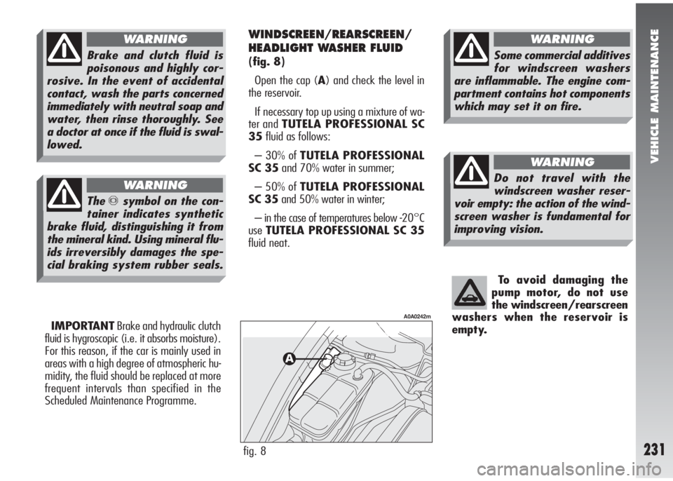
(fig. 8)
Open the cap (A) and check the level in
the reservoir.
If necessary top up using a mixture of wa-
ter and TUTELA PROFESSIONAL SC
35fluid as follows:
– 30% of TUTELA PROFESSIONAL
SC 35and 70% water in summer;
– 50% of TUTELA PROFESSIONAL
SC 35and 50% water in winter;
– in the case of temperatures below -20°C
useTUTELA PROFESSIONAL SC 35
fluid neat.
fig. 8
A0A0242m
Theπsymbol on the con-
tainer indicates synthetic
brake fluid, distinguishing it from
the mineral kind. Using mineral flu-
ids irreversibly damages the spe-
cial braking system rubber seals.
WARNING
Brake and clutch fluid is
poisonous and highly cor-
rosive. In the event of accidental
contact, wash the parts concerned
immediately with neutral soap and
water, then rinse thoroughly. See
a doctor at once if the fluid is swal-
lowed.
WARNING
Do not travel with the
windscreen washer reser-
voir empty: the action of the wind-
screen washer is fundamental for
improving vision.
WARNING
Some commercial additives
for windscreen washers
are inflammable. The engine com-
partment contains hot components
which may set it on fire.
WARNING
Page 242 of 291

VEHICLE MAINTENANCE
240
HEADLIGHT WASHERS
Regularly check that the spray jets are in-
tact and clean (fig. 17).
If it is necessary to direct the jet, contact
an Alfa Romeo Authorised Service.
BODYWORK
PROTECTION FROM
ATMOSPHERIC AGENTS
The main causes of corrosion are:
– atmospheric pollution
– salty air and humidity (coastal areas, or
hot humid climates)
– seasonal environment conditions.
Not to be underestimated is also the abra-
sive action of wind-borne atmospheric dust
and sand and mud and gravel raised by oth-
er vehicles.
On your
Alfa 147 GTA, Alfa Romeo
has implemented the best manufacturing
technologies to effectively protect the body-
work against corrosion.
These include:
– Painting products and systems which
give the vehicle particular resistance to cor-
rosion and abrasion.
– Use of galvanised (or pretreated) steel
sheets, with high resistance to corrosion.
– Spraying the underbody, engine com-
partment, wheel arches and other parts with
highly protective wax products.
fig. 17
A0A0425m
– Spraying of plastic parts, with a protec-
tive function, in the more exposed points:
underdoor, inner wheel arch linings, etc.
– Use of “open” boxed sections to pre-
vent condensation and pockets of moisture
from triggering rust inside.
VEHICLE EXTERIOR AND
UNDERBODY WARRANTY
TheAlfa 147 GTAis guaranteed
against perf oration due to rust of any orig-
inal element of the structure or body. For the
general terms of this warranty, refer to the
Warranty Booklet.
Page 243 of 291
VEHICLE MAINTENANCE
241
ADVICE FOR PRESERVING
THE BODYWORK
Paint
The paintwork does not only serve an aes-
thetic purpose but also protects the under-
lying sheet metal.
In the case of deep scrapes or scores, you
are advised to have the necessary touch-
ing up carried out immediately to avoid the
formation of rust.
Only original products should be used for
touching up paint (see “Body paint identi-
fication plate” in the “Technical Specifica-
tions” chapter).
Normal paint maintenance consists in
washing at intervals depending on the con-
ditions and environment of use. For exam-
ple, in highly polluted areas, or if the roads
are sprayed with salt, it is wise to wash the
car more frequently.Do not wash the vehicle after it has been
left in the sun or with the bonnet hot: this
may alter the shine of the paintwork.
Exterior plastic parts must be cleaned in
the same way as the rest of the vehicle.
Where possible, do not park under trees;
the resinous substance many species release
give the paint a dull appearance and in-
crease the possibility of triggering rust
processes.
IMPORTANTBird droppings must be
washed off immediately and thoroughly as
the acid they contain is particularly aggres-
sive.
Windows
Use specific products to clean the windows.
Use clean cloths to avoid scratching or al-
tering the transparency of the glass.
IMPORTANTThe inside of the
rearscreen should be wiped gently with a
cloth in the direction of the filaments to
avoid damaging the heating device. Detersives pollute water.
The car should therefore be
washed in areas equipped
for the collection and purification
of the liquid used in the washing
process.
To correctly wash the car:
1) Remove the aerial from the roof to pre-
vent damage to it if the car is washed in
an automatic system.
2) Spray the vehicle with a low pressure
jet of water.
3) Pass a sponge moistened with a light
detergent solution, rinsing the sponge fre-
quently.
4) Rinse well with water and dry with a
jet of air or chamois leather.
When drying, take particular care with the
less visible parts like door surrounds, bon-
net and around the headlights where wa-
ter may stagnate. The vehicle should not be
taken to a closed area immediately, but left
in the open so that residual water can evap-
orate.
Page 262 of 291
RIGHT HAND DRIVE VERSION
260
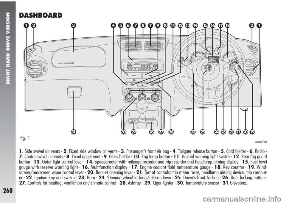
DASHBOARD
1. Side swivel air vents - 2. Fixed side window air vents - 3. Passenger’s front Air bag - 4. Tailgate release button - 5. Card holder - 6. Radio -
7. Centre swivel air vents - 8. Fixed upper vent - 9. Glass holder - 10. Fog lamp button - 11. Hazard warning light switch - 12. Rear fog guard
button - 13. Outer light control lever - 14. Speedometer with mileage recorder and trip recorder and headlamp aiming display - 15. Fuel level
gauge with reserve warning light - 16. Multifunction display - 17. Engine coolant fluid temperature gauge - 18. Rev counter - 19. Wind-
screen/rearscreen wiper control lever - 20. Bonnet opening lever - 21. Set of controls: trip meter reset, headlamp aiming device, trip comput-
er - 22. Ignition key and switch - 23. Horn - 24. Steering wheel locking/release lever - 25. Driver’s front Air bag - 26. Door locking button -
27. Controls for heating, ventilation and climate control - 28. Ashtray - 29. Cigar lighter - 30. Temperature sensor - 31Glovebox.
fig. 1A0A0475m