Alfa Romeo 156 2006 Owner handbook (in English)
Manufacturer: ALFA ROMEO, Model Year: 2006, Model line: 156, Model: Alfa Romeo 156 2006Pages: 357, PDF Size: 5.04 MB
Page 131 of 357

GETTING TO KNOW YOUR CAR
129
fig. 111
A0B0072m
INSIDE AIR RECIRCULATION
ON/OFF BUTTON
v
(fig. 111)
Inside air recirculation is controlled ac-
cording to three operating logics:
– automatic control, indicated by the turn-
ing on of the right led on the button;
– forced switching on (inside air recircu-
lation always on), indicated by the turning
on of the left led on the button (and by the
right led going off at the same time);
– forced switching off (inside air recircu-
lation always off, with air inlet from the out-
side), indicated by the turning off of both
leds.
These operating conditions are obtained
by pressing in sequence the inside air recir-
culation button (7)
v
.
When inside air recirculation is controlled
automatically by the system, the right led
on the air recirculation button (7)
v
stays on all the time and the left led shows
the air recirculation condition:
ON= air recirculation operating;
OFF= air recirculation off.If inside air recirculation has been switched
on or off manually, the led on button (14)
AUTO
turns off.In automatic operation, inside air recircu-
lation is switched on automatically when the
anti-pollution sensor detects the presence of
polluted air, for instance in cities, queues,
tunnels, and when the windscreen
wash/wiper is operated (with the charac-
teristic smell of spirit).
Page 132 of 357

GETTING TO KNOW YOUR CAR
130
With the outside temper-
ature below 2°C the cli-
mate control compressor is unable
to work. It is therefore inadvisable
to use the inside air recirculation
function v
with low outside tem-
perature as windows may mist
over quickly.WARNING
The inside air recirculation
function makes it possible
to reach the required “heating” or
“cooling” conditions faster. It is
however inadvisable to use it on
rainy/cold days as it would con-
siderably increase the possibility of
the windows misting inside, espe-
cially if the climate control system
is off.
WARNING
It is advisable to turn on the
inside air recirculation sys-
tem in queues or tunnels to avoid
admitting polluted air from outside.
The prolonged use of this function
should however be avoided, espe-
cially with several persons on
board, to avoid the possibility of the
windows misting inside.
WARNING
In certain weather condi-
tions (e.g. outside temper-
ature around 0°C) and with auto-
matic air recirculation control on,
mist may form on the windows. In
this case press the inside air re-
circulation button (7)
v
, to
switch off recirculation (leds on
button off) and if necessary in-
crease the flow of air to the wind-
screen.
WARNING
Page 133 of 357

GETTING TO KNOW YOUR CAR
131
BUTTON AUTO AUTOMATIC
OPERATION
(fig. 112)
When button (14)
AUTO
is pressed, the
system automatically regulates the amount
and distribution of the air admitted into the
passenger compartment, clearing all the pre-
vious manual settings.
This condition is indicated by the lighting
of both button leds.
When the right led, on button (14)
AUTO
,
is OFF, it indicates that one or several man-
ual operations have been carried out and,
therefore, that automatic control is not com-
plete (except for temperature control, which
is always automatic) indicated by the left
led on.
fig. 112
A0B0073m
Page 134 of 357

GETTING TO KNOW YOUR CAR
132
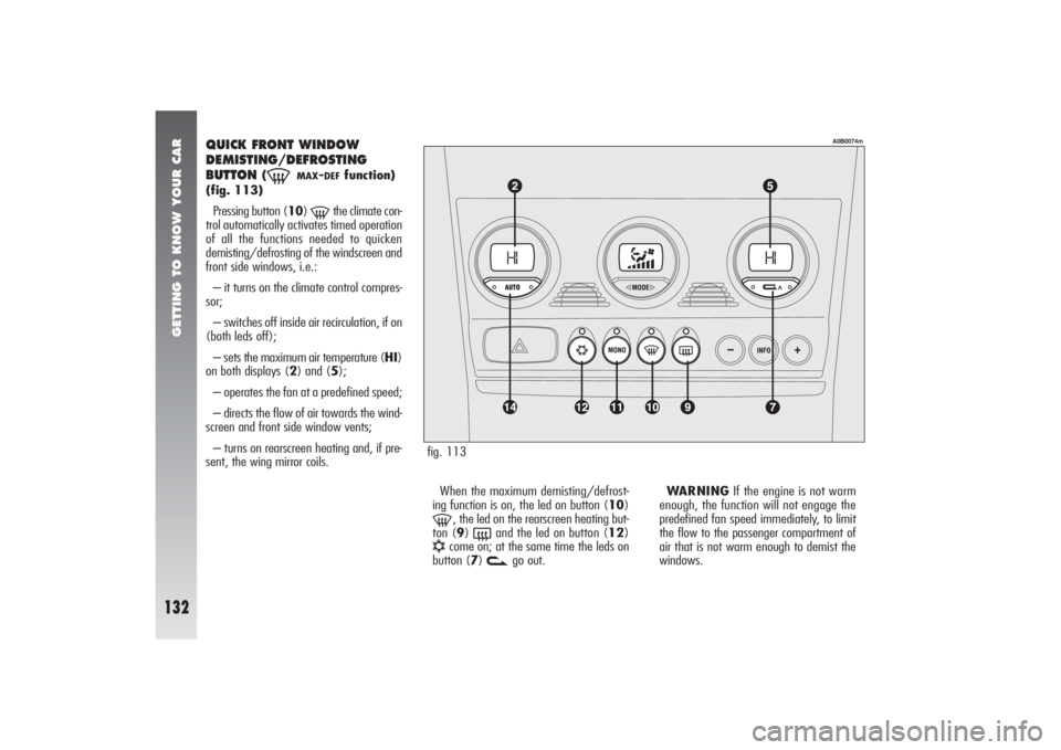
fig. 113
A0B0074m
QUICK FRONT WINDOW
DEMISTING/DEFROSTING
BUTTON
(-
MAX
-DEF
function)
(fig. 113)
Pressing button (10)
-
the climate con-
trol automatically activates timed operation
of all the functions needed to quicken
demisting/defrosting of the windscreen and
front side windows, i.e.:
– it turns on the climate control compres-
sor;
– switches off inside air recirculation, if on
(both leds off);
– sets the maximum air temperature (HI)
on both displays (2) and (5);
– operates the fan at a predefined speed;
– directs the flow of air towards the wind-
screen and front side window vents;
– turns on rearscreen heating and, if pre-
sent, the wing mirror coils.
When the maximum demisting/defrost-
ing function is on, the led on button (10)
-
, the led on the rearscreen heating but-
ton (9)
(
and the led on button (12)
√
come on; at the same time the leds on
button (7)
v
go out.WARNINGIf the engine is not warm
enough, the function will not engage the
predefined fan speed immediately, to limit
the flow to the passenger compartment of
air that is not warm enough to demist the
windows.
Page 135 of 357

GETTING TO KNOW YOUR CAR
133
When the maximum demisting/defrost-
ing function is on, the only manual opera-
tions possible are manual adjustment of the
fan and switching rearscreen heating off.
Pressing one of the following buttons:
(10)
-
, (7)
v
, (11)
MONO
, (14)
AUTO
or (12)
√
the system switches off
the maximum demisting/defrosting func-
tion, resuming the system operating condi-
tions prior to turning it on, in addition to
activating the last function required, if any.
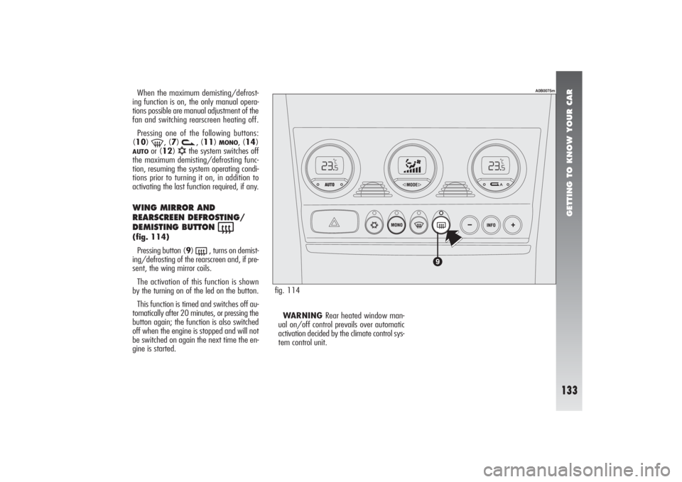
WING MIRROR AND
REARSCREEN DEFROSTING/
DEMISTING BUTTON
(
(fig. 114)
Pressing button (9)
(
, turns on demist-
ing/defrosting of the rearscreen and, if pre-
sent, the wing mirror coils.
The activation of this function is shown
by the turning on of the led on the button.
This function is timed and switches off au-
tomatically after 20 minutes, or pressing the
button again; the function is also switched
off when the engine is stopped and will not
be switched on again the next time the en-
gine is started.WARNING Rear heated window man-
ual on/off control prevails over automatic
activation decided by the climate control sys-
tem control unit.
fig. 114
A0B0075m
Page 136 of 357

GETTING TO KNOW YOUR CAR
134
This function is timed and switches off au-
tomatically after 20 minutes, or pressing the
button again; the function is also switched
off when the engine is stopped and will not
be switched on again the next time the en-
gine is started.
WARNINGThe system turns on
rearscreen heating automatically if the tem-
perature is below 3°C.
WARNINGDo not apply stickers on the
inside of the rearscreen over the heating fil-
aments to avoid damage that might cause
it to stop working properly.
WARNINGWhen reconnecting the neg-
ative battery cable after having disconnected
it, wait for 2 minutes before turning the key
to enable the climate control system to re-
set actuator strokes properly.
POLLEN FILTER This filter has the specific capability of com-
bining the mechanical filtering of the air with
an electrostatic effect so that the outside air
admitted to the passenger compartment is
purified and free from particles such as dust,
pollen, etc.
In addition to the above, it also effectively
reduces the concentration of pollutants.
The filtering action takes place under all
air inlet conditions and it is clearly most ef-
fective with the windows shut.
Have the conditions of the filter checked by
Alfa Romeo Authorized Services at least once
a year, preferably on the onset of summer.If the vehicle is used mainly in polluted
or dusty areas it should be checked and if
necessary replaced, at shorter intervals.
Failure to replace the fil-
ter may considerably re-
duce the effectiveness of
the climate control system up to
blocking the air flow from the out-
lets and vents.
Page 137 of 357

GETTING TO KNOW YOUR CAR
135
ADDITIONAL HEATER(JTD engines) (for versions/
markets where applicable)
The car is equipped with an additional
heater (not programmable) which supports
the engine during cold or winter weather
to quickly reach a comfortable temperature
inside the passenger compartment.
The heater operates with the engine run-
ning when the outside temperature is below
20°C and the engine has not yet reached
normal operating temperature.
HAZARD WARNING LIGHTS(fig. 116)
They are switched on by pressing button
(A), regardless of the position of the igni-
tion key.
When the hazard warning lights are
switched on, the switch itself begins to flash
together with the direction indicator warn-
ing lights and the emergency indicator on
the instrument panel. This functions is
switched off by pressing the button again.
CONTROLSTAILGATE OPENING
(fig. 115)
To open the boot pull the lever (A) at the
side of the driver’s seat.
fig. 115
A0B0042m
fig. 116
A0B0036m
Do not operate the boot re-
lease lever with the car on
the move.
WARNING
Use of the hazard warning
lights is ruled by the High-
way Code of the country in which
the car is used. Observe regula-
tions.
WARNING
Page 138 of 357

GETTING TO KNOW YOUR CAR
136
DASHBOARD LIGHTING
ADJUSTMENT
(fig. 118)
When the outside lights are on, the dash-
board lighting is adjusted by pressing button
(A).
Each press of the button (A) cyclically se-
lects one of the three lighting levels pro-
vided: low-medium-high.
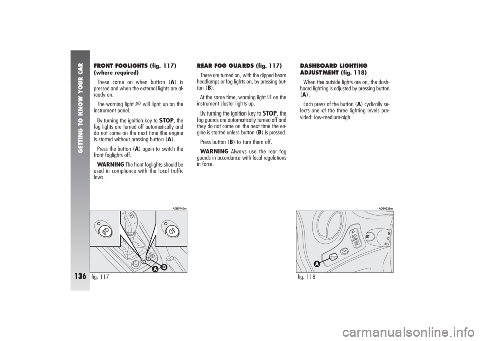
FRONT FOGLIGHTS
(fig. 117)
(where required)
These come on when button (A) is
pressed and when the external lights are al-
ready on.
The warning light
5
will light up on the
instrument panel.
By turning the ignition key to STOP, the
fog lights are turned off automatically and
do not come on the next time the engine
is started without pressing button (A).
Press the button (A) again to switch the
front foglights off.
WARNINGThe front foglights should be
used in compliance with the local traffic
laws.
REAR FOG GUARDS
(fig. 117)
These are turned on, with the dipped beam
headlamps or fog lights on, by pressing but-
ton (B).
At the same time, warning light
4
on the
instrument cluster lights up.
By turning the ignition key to STOP, the
fog guards are automatically turned off and
they do not come on the next time the en-
gine is started unless button (B) is pressed.
Press button (B) to turn them off.
WARNINGAlways use the rear fog
guards in accordance with local regulations
in force.
fig. 117
A0B0740m
fig. 118
A0B0326m
Page 139 of 357

GETTING TO KNOW YOUR CAR
137
Inspect the care carefully to make sure that
there are no fuel leaks, for instance in the
engine compartment, under the vehicle or
near the tank area.
If no leaks are found and the vehicle can
be restarted again, press button (A) to ac-
tivate the fuel supply system.
After a collision, remember to turn the ig-
nition key to STOP so as not to run the bat-
tery down.
INERTIAL FUEL CUT-OFF
SWITCH
(fig. 119)
This is an automatic safety switch which is
triggered in the event of crash to interrupt
the flow of fuel.
The intervention of the inertial switch is in-
dicated by a message + symbol on the In-
focenter display (see “Infocenter Display”
in this chapter) and by the door unlocking.
fig. 119
A0B0574m
fig. 120
A0B0044m
OPENING THE FUEL FLAP(fig. 120)
The fuel flap is released from inside the car
raising the front part of the lever (A).
If a smell of fuel is noted
following an accident, or
the fuel system is leaking, to avoid
the risk of fire do not reset the
switch.
WARNING
Page 140 of 357

GETTING TO KNOW YOUR CAR
138
HEADLIGHT CORRECTOR (fig. 121)
If the car is fitted with xenon headlights,
beam aiming is electronic and therefore con-
trol (A) on the mask near the steering col-
umn is not present.
The headlights should be aimed correctly
depending on the vehicle load.
The control (A) on the plate at the side of
the steering column can be moved to four
positions corresponding to the vehicle loads
given below:
position 0: 1 or 2 people occupying front
seats, full fuel tank, on-board equipment pre-
sent;
position 1: 5 people on-board;fig. 121
A0B0240m
HAND BRAKE
(fig. 122)
The hand brake lever is located between
the two front seats.
To operate the brake when the vehicle is
“stationary”, pull the lever (A) upwards un-
til the required braking action is obtained.
When the ignition key is in the MARpo-
sition, the
x
warning light will come on on
the instrument panel.
fig. 122
A0B0288m
position 2: 5 people on-board, luggage
compartment full (50 kg approximately);
position 3: Driver and 300 kg in luggage
compartment.
Check the positioning of
the headlight beams every
time you change the load to be car-
ried.
WARNING