ignition Alfa Romeo 156 2006 Owner handbook (in English)
[x] Cancel search | Manufacturer: ALFA ROMEO, Model Year: 2006, Model line: 156, Model: Alfa Romeo 156 2006Pages: 357, PDF Size: 5.04 MB
Page 158 of 357
GETTING TO KNOW YOUR CAR
156
SPORT(button (A-fig. 139)
pressed):
This is selected when wanting to avail of
the vehicle’s peak performance for sporty
driving or on demanding routes.
Driving in the SPORTmode increases fuel
consumption.
WARNINGThe CITYor SPORTdri-
ving modes can be selected under any con-
dition (vehicle stationary or on the move).
WARNINGWhen the car is started with
a cold engine, the system selects the
SPORTdriving mode, even if the CITY
mode has been selected, until the engine
reaches normal operating temperature.
C/S
ICE( button (B-fig. 133) pressed):
This driving mode is recommended when
the road surface offers poor grip (snow, ice,
etc.). Moving off takes place in 2
ndgear.
The ICEdriving mode is available only with
the selector lever at D.
Moving the lever from D, the ICEmode
is automatically cut off.
WARNINGThe ICEdriving mode can
be engaged pressing the corresponding but-
ton also with the car on the move, provided
that the speed is below 45 km/h.
ICE
SELECTING THE DRIVING
MODESThe automatic gearbox for this car is con-
trolled electronically and includes the selec-
tion of three different driving modes, thereby
giving the best response in terms of driving
comfort, consumption levels, sporty perfor-
mance and travelling safety.
The three driving modes CITY, SPORT
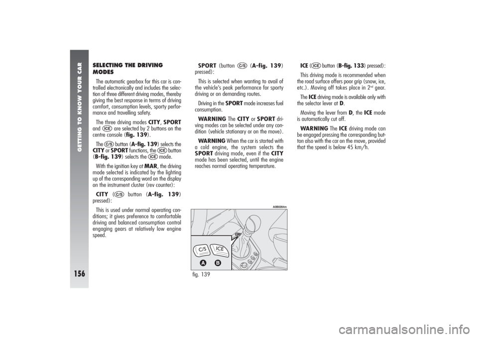
and are selected by 2 buttons on the
centre console (fig. 139).
The button (A-fig. 139) selects the
CITYor SPORTfunctions, the button
(B-fig. 139) selects the mode.
With the ignition key at MAR, the driving
mode selected is indicated by the lighting
up of the corresponding word on the display
on the instrument cluster (rev counter):
CITY( button (A-fig. 139)
pressed):
This is used under normal operating con-
ditions; it gives preference to comfortable
driving and balanced consumption control
engaging gears at relatively low engine
speed.
C/S
ICE
ICE
C/SICE
fig. 139
A0B0264m
Page 160 of 357
GETTING TO KNOW YOUR CAR
158
1st2nd3rd4th
2nd2nd4th4th
Gear engaged Gear ratiomanually available
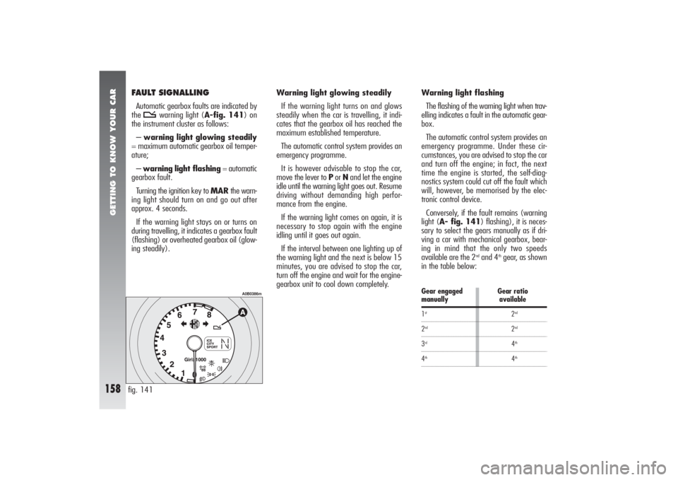
FAULT SIGNALLINGAutomatic gearbox faults are indicated by
the t
warning light (A-fig. 141) on
the instrument cluster as follows:
–warning light glowing steadily
= maximum automatic gearbox oil temper-
ature;
–warning light flashing= automatic
gearbox fault.
Turning the ignition key to MARthe warn-
ing light should turn on and go out after
approx. 4 seconds.
If the warning light stays on or turns on
during travelling, it indicates a gearbox fault
(flashing) or overheated gearbox oil (glow-
ing steadily).Warning light glowing steadily
If the warning light turns on and glows
steadily when the car is travelling, it indi-
cates that the gearbox oil has reached the
maximum established temperature.
The automatic control system provides an
emergency programme.
It is however advisable to stop the car,
move the lever to Por Nand let the engine
idle until the warning light goes out. Resume
driving without demanding high perfor-
mance from the engine.
If the warning light comes on again, it is
necessary to stop again with the engine
idling until it goes out again.
If the interval between one lighting up of
the warning light and the next is below 15
minutes, you are advised to stop the car,
turn off the engine and wait for the engine-
gearbox unit to cool down completely.
fig. 141
A0B0386m
Warning light flashing
The flashing of the warning light when trav-
elling indicates a fault in the automatic gear-
box.
The automatic control system provides an
emergency programme. Under these cir-
cumstances, you are advised to stop the car
and turn off the engine; in fact, the next
time the engine is started, the self-diag-
nostics system could cut off the fault which
will, however, be memorised by the elec-
tronic control device.
Conversely, if the fault remains (warning
light (A- fig. 141) flashing), it is neces-
sary to select the gears manually as if dri-
ving a car with mechanical gearbox, bear-
ing in mind that the only two speeds
available are the 2
ndand 4
thgear, as shown
in the table below:
Page 163 of 357

GETTING TO KNOW YOUR CAR
161
INTERNAL FITTINGSGLOVEBOX On the dashboard there is a key glovebox
with light.The compartment is lit by a courtesy light
when it is open (when the ignition key is
at MAR(B-fig. 143).
There is a recess on the lid (C-fig. 143)
for inserting a pen or pencil. For the versions
/ markets where provided, the closure flap
is fitted with a lock. The lock can be
opened/closed using the ignition key.
GRAB HANDLES
(fig. 144)
Grab handles are set above the front doors.
Two grab handles (A) fitted with a coat
hook (B) are located above the rear doors.
fig. 142
A0B0587m
fig. 144
A0B0124m
fig. 143
A0B0261m
To open the glovebox use lever (A-
fig. 142).
Do not travel with the
glovebox open; it could
harm the passenger in the event of
an accident.
WARNING
Page 164 of 357

GETTING TO KNOW YOUR CAR
162
CEILING LIGHTS The car is fitted with passenger’s com-
partment ceiling lights (front/rear) with
gradual switching on/off. Timings, defined
as max. switching on time elapsing between
the end of gradual switching on and the start
of gradual switching off are as follows:
1)approx. 6 seconds when:
– unlocking the doors manually or by the
remote control
– closing the driver’s door to get into the
car and fit the key into the ignition switch
– removing the key from the ignition
switch.
2)approx. 3 minutes from the door open-
ing.WARNING With ignition key at STOP
or when opening a door or the tailgate 15
minutes timing is activated, then ceiling
lights go off. Timing restarts each time a
door/tailgate is opened.
Front roof light (fig. 145)
The roof light comprises two lights with the
control switch.
With switch (A) in the central position
(1), both lights turn on when a door is
opened.
When the doors are closed, a timer is ac-
tivated for about 7 seconds, to allow the car
to be started. The lights go out when the ig-
nition key is turned to MAR(with the doors
closed).
Moving switch (A) to the left (position 0),
the lights stay off (position OFF).Moving switch (A) to the right (posi-
tion2) both lights stay on.
The spot function is operated by switch
(B).
Moving switch (B) to the left (position 1)
the left spot light turns on. Moving switch
to the right (position 2) the right spot light
turns on.
With switch (B) in the central position (po-
sition 0) the spotlights stay off.
WARNINGBefore leaving the car, make
sure that both switches are in the central po-
sition. This way, the roof lights will go out
when the doors are closed. If a door is left
open, the lights will go out automatically af-
ter a few seconds.
To turn them on again, simply open an-
other door or close the same one and open
it again.fig. 145
A0B0575m
Page 165 of 357

GETTING TO KNOW YOUR CAR
163
fig. 146
A0B0259m
Courtesy light (fig. 146)
(where required)
Lowering the passenger’s sun visor, the
courtesy light on the roof lining can be seen.
This light makes it possible to use the cour-
tesy mirror under conditions with dim light.
On Sportwagon versions there is also a
courtesy light under the driver’s sun visor.
Use switch (A) to turn it on and off, with
the ignition key at MAR.Rear roof light (fig. 147)
(except versions with sunroof)
In correspondence with each rear door
there is a light which turns on automatically
when a door is opened.
They are timed and work in the same way
as described for the front roof light.
They can be turned on and off by hand
pressing the transparent cover (A) on the
circular impression.Centre rear roof lamp (fig. 148)
(only versions with sunroof)
On the roof lamp there is a switch with
three positions.
When the switch (A) is in the central po-
sition (0) the roof lamp turns on automat-
ically when a door is opened.
Lighting up is timed and it works as de-
scribed for the front roof lamp.
Moving the switch to the right (position 1)
the roof lamp stays off all the time.
Moving the switch to the left (position 2)
the roof lamp stays on all the time.
WARNINGBefore leaving the car make
sure that the switch (A) is in the central po-
sition (0), so that the lamp goes out when
the doors are closed.
fig. 147
A0B0258m
fig. 148
A0B0257m
Page 169 of 357
GETTING TO KNOW YOUR CAR
167
RADIO
TRANSMITTERS
AND CELLPHONESCellphones and other radio transmitters
(e.g. CB radios) cannot be used inside the
vehicle, unless you use a separate aerial
mounted outside the vehicle.
The transmission and reception efficiency
of this equipment may also be affected by
the shielding effect of the vehicle’s body.
SUNROOF(optional for versions/markets
where applicable)
The sunroof can only be operated when
the ignition key is in the MARposition.Do not open the sunroof
when snow or ice are on
the roof as this may dam-
age it.
The use of cellphones, CB
radios or similar inside the
passenger compartment (without
an outside aerial) produces electro-
magnetic RF fields; if these are am-
plified by the resonance inside the
passenger compartment, they may
not only result in a potential health
hazard, or poor functioning of the
electronic systems such as engine
control units, ABS/EBD control
units, etc., fitted to the vehicle, but
also put the safety of your vehicle
in jeopardy.
WARNING
Improper use of the sunroof
can be dangerous. Before
and while operating it, always
make sure that the passengers are
not exposed to the risk of harm
caused either directly by the sunroof
in motion or by personal items
drawn or knocked by it.
WARNING
When leaving the vehicle,
the ignition key should al-
ways be removed to avoid acci-
dents involving the sunroof which
could be inadvertently operated by
any passenger remaining in the ve-
hicle.
WARNING
Page 175 of 357

GETTING TO KNOW YOUR CAR
173
– Press the safety lever (fig. 167) up-
wards.
– Raise the bonnet.
WARNINGBonnet raising is aided by
two gas springs. Do not tamper with these
springs and accompany the bonnet while
raising it.
fig. 167
A0B0576m
Before lifting the bonnet,
make sure that the wind-
screen wiper arms are not raised
from the windscreen.
WARNING
DANGER-SERIOUS INJURY.
When carrying out checks
or maintenance operations in the
engine compartment, take special
care not to bump the head on the
raised bonnet.
WARNING
If checks need to be carried
out in the engine compart-
ment when the engine is still
warm, keep away from the fan as
it could start up even when the key
is removed from the ignition. Wait
until the engine cools down.
WARNING
Scarves, ties and loose
clothing may be caught in
the moving parts.
WARNING
To close:
– lower the bonnet to approx. 20 cm from
the engine compartment, then let it drop.
Try lifting it to make sure that it is shut com-
pletely and not simply caught in the safety
position.
If the bonnet does not close properly, do
not push it down but open it again and re-
peat the above procedure.
For safety reasons the
bonnet shall always be
perfectly closed when travelling.
Always check for proper bonnet
locking. If the bonnet is left inad-
vertently open, stop the car im-
mediately and close the bonnet.
WARNING
Page 184 of 357
GETTING TO KNOW YOUR CAR
182
EOBD SYSTEMThe EOBD (European On Board Diagnosis)
system fitted in the car conforms with the
98/69/EC (EURO 3) Directive and the
2001/1/EC Directive, level B (EURO4) for
2.0 JTS, 2.0 JTS Selespeed and JTD 20V
Multijet versions.
This system continuously monitors the
components of the vehicle related to emis-
sions; it also indicates, when the warning
light
U
comes on on the instrument panel
(together with the message + symbol
shown by the display) that the components
in question are in poor conditions.
The objective is the following:
– to keep under control the efficiency of
the system;
– to indicate when a malfunction causes
an increase in the emissions beyond the
threshold established by European regula-
tions;
– to indicate the need to replace the de-
teriorated components.
The system also has a diagnostic connec-
tor, which can be interfaced with adequate in-
struments, that enables the error codes stored
in the control unit to be read, together with
a series of specific parameters concerning the
operation and diagnosis of the engine.This check can also be made by the traf-
fic control agents.
If, when the ignition key
is turned to MAR, the
U
warning light does not
come on or if, when driving, it
lights up and emits a fixed light or
a flashing one (together with the
message + symbol shown by the
display), contact an Alfa Romeo
Authorized Service Station as soon
as possible. The operation of the
U
warning light can also be
checked by means of special equip-
ment available to the traffic con-
trol officers. Comply with the reg-
ulations in force in country where
you drive your car.
WARNINGAfter the problem has beel
resolved, to completely check the system,
the Alfa Romeo Authorized Services must
carry out tests on a test bench and, if nec-
essary, road tests that could be long.
WARNING LIGHT ON
INSTRUMENT PANELWhen the ignition key is turned to MAR,
the dial warning light
á
comes on but must
go out after a few seconds.
If the warning light does not go out, or if it
stays on (together with the message + sym-
bol on the display and the coming on of the
ASR button led) when the vehicle is running,
contact Alfa Romeo Authorized Services.
The flashing of the warning lamp when the
vehicle is running indicates the actuation of
the VDC system.
VDC system failure warning
In the event of a failure the VDC system
disengages automatically and the
á
warn-
ing light on the instrument cluster turns on
glowing steadily (together with the message
+ symbol shown on the display and the com-
ing on of the ASR button led).
In the event of a VDC system failure the
car behaves like a vehicle not fitted with this
system: in any case it is advisable to con-
tact Alfa Romeo Authorized Services as soon
as possible.
Page 190 of 357

GETTING TO KNOW YOUR CAR
188
EMISSION REDUCING DEVICES
(petrol engines)Trivalent catalytic converter
(catalytic silencer)
The exhaust system is fitted with a cat-
alyzer formed of alloys of noble metals. It
is housed in a stainless steel container which
is able to resist the high operating temper-
atures.
The catalyzer converts the unburnt hydro-
carbons, carbon monoxide and nitrogen ox-
ides present in the exhaust gas (even if in
small quantities thanks to the electronic in-
jection and ignition system) into harmless
compounds.Lambda probe
A sensor (lambda probe) measures the
content of oxygen present in the exhaust
gas. The signal transmitted by the lambda
probe is use by the injection and ignition
electronic control unit to adjust the air-fuel
mixture.
Anti-evaporation system
As it is impossible, even when the engine
is switched off, to prevent the formation of
fuel vapours, a system has been devised
which imprisons the vapours in a special ac-
tivated carbon container.
During operation of the engine, these
vapours are sucked up and sent to com-
bustion.
EMISSION REDUCING DEVICES
(JTD engines )Oxidising catalytic converter
Converts the polluting substances present
in the exhaust gases (carbon monoxide, un-
burned hydrocarbons and particulate) into
harmless substances, thus reducing the
fumes and smell that are typical of diesel
engines.
The catalytic converter consists of a stain-
less steel case that houses a ceramic hon-
eycomb body coated with noble metal used
as a catalyst.
Exhaust gas recirculation system
(E.G.R.)
This system recycles, i.e. re-uses, a vary-
ing percentage of the exhaust gases, de-
pending on engine operating conditions.
It is used, when necessary, to control ni-
tric oxides.
Due to the high tempera-
tures reached during oper-
ation of the catalytic converter, the
vehicle should not be parked over
inflammable materials (paper, fuel
oils, grass, dry leaves, etc.).
WARNING
Page 191 of 357

CORRECT USE OF THE CAR
189
PROCEDURE FOR PETROL
ENGINESWARNINGIt is important not to press
the accelerator until the engine has started.
1) Make sure the handbrake is engaged.
2)Move the gear lever to neutral.
3)Fully depress the clutch pedal so that
the starter motor is not forced to crank the
toothed wheels of the gearbox.
4)Ensure that the systems and electrical
devices, especially if they absorb high quan-
tities of energy (e.g. heated rear wind-
screen) are switched off.
5)Turn the ignition to the AV Vposition
and release it as soon as the engine starts.
6)If the engine does not start, return the
key to the STOPposition and repeat the
operation.
WARNINGIf it is difficult to start the en-
gine do not insist with extended attempts
which may damage the catalyzer but con-
tact Alfa Romeo Authorized Services. The ignition switch is fitted with a safety
device which obliges the driver to return the
ignition key to the STOPposition before re-
peating the starting operation if the engine
does not start immediately.
Similarly, when the engine is running, the
device prevents the key being moved from
the MARto the AV Vposition.
STARTING
THE ENGINEWARNINGThe car is fitted with an elec-
tronic engine lock device. If the engine fails
to start see “Alfa Romeo CODE system”.
C C
O O
R R
R R
E E
C C
T T
U U
S S
E E
O O
F F
T T
H H
E E
C C
A A
R R
In addition to the notes
and specifications given be-
low we recommend that,
during the initial period, you do not
drive to full vehicle performance
(for example excessive accelera-
tion, long journeys at top speed,
hard braking, etc.).
To avoid useless con-
sumption of power and
possible draining the bat-
tery, never leave the ignition key
in the MAR position when the en-
gine is not running.
Running the engine in con-
fined areas is extremely
dangerous. The engine consumes
oxygen and produces carbon
monoxide which is a highly toxic
and lethal gas.
WARNING