instrument panel Alfa Romeo 156 2006 Owner handbook (in English)
[x] Cancel search | Manufacturer: ALFA ROMEO, Model Year: 2006, Model line: 156, Model: Alfa Romeo 156 2006Pages: 357, PDF Size: 5.04 MB
Page 21 of 357

GETTING TO KNOW YOUR CAR19
OPENING/CLOSING
FROM INSIDEFront doors
– To open the door pull the handle (A-
fig. 16) regardless of the position of knob
(B).
– To close the door pull the flap. To pre-
vent the door from being opened from out-
side press knob (B).Rear doors fig. 15
A0B0025m
fig. 16
A0B0024m
fig. 17
A0B0026m
– To open the door pull handle (A-
fig. 17).
– To close the door press the knob (B)
even when the flap is open, and then close
the flap.
If the boot is not properly shut, the warn-
ing light ´will come on on the instrument
panel or (where applicable) on the Info-
center display (together with relevant mes-
sage).
CENTRALIZED LOCKINGThis permits centralized locking of all
doors, both front and rear.
To operate the centralized locking device
the doors must be perfectly closed otherwise
the system will not work.
For versions/markets, where applicable,
central locking depends on the complete
closing of all the doors and of the boot.
– From outside:when the doors are
closed, insert and turn the key in the lock of
one of the two front doors.
– From inside:when the doors are
closed, press one of the knobs (B-fig. 16)
located on the front doors, engage/release
the centralized locking system.
The rear doors can only be
opened if the child safety
lock has been released.
WARNING
Page 50 of 357
GETTING TO KNOW YOUR CAR48
fig. 70
A0B0373m
STEERING WHEEL
LEVERSThe devices and services controlled by the
levers on the steering wheel can only be ac-
tivated when the ignition key is in the MAR
position.LEFT-HAND LEVERThe left-hand lever controls the external
lights except the foglamps and the rear fog-
light.
When the external lights are switched on
the various controls located on the dash-
board are illuminated.
The sidelights will come on if the ignition
key is in the PARKposition, regardless of
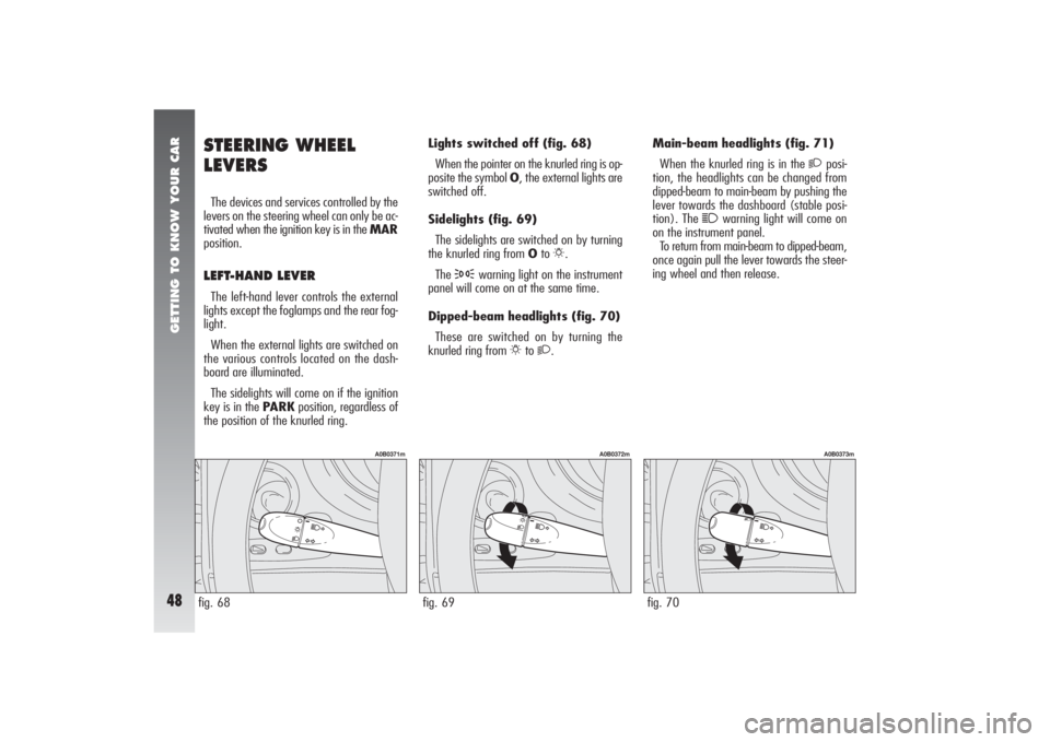
the position of the knurled ring.Lights switched off (fig. 68)
When the pointer on the knurled ring is op-
posite the symbol O, the external lights are
switched off.
Sidelights (fig. 69)
The sidelights are switched on by turning
the knurled ring from Oto
6.
The
3
warning light on the instrument
panel will come on at the same time.
Dipped-beam headlights (fig. 70)
These are switched on by turning the
knurled ring from
6
to 2
.Main-beam headlights (fig. 71)
When the knurled ring is in the
2
posi-
tion, the headlights can be changed from
dipped-beam to main-beam by pushing the
lever towards the dashboard (stable posi-
tion). The
1
warning light will come on
on the instrument panel.
To return from main-beam to dipped-beam,
once again pull the lever towards the steer-
ing wheel and then release.
fig. 68
A0B0371m
fig. 69
A0B0372m
Page 51 of 357

GETTING TO KNOW YOUR CAR49
Flashing (fig. 72)
The headlights are flashed by pulling the
lever towards the steering wheel (unstable
position) regardless of the position of the
knurled ring. The
1
warning light on the
instrument panel will come on at the same
time.
WARNINGOnly the main-beam lights
are flashed. To avoid penalties, follow lo-
cal regulations.Direction indicators (fig. 73)
Moving the lever to the stable position will:
up - engage the right-hand direction indi-
cators.
down - engage the left-hand direction in-
dicators.
One of the warning lights (
R
or
E) will
come on on the instrument panel at the
same time.
The lever is returned to its home position
automatically and the indicators are
switched off when the steering wheel is
straightened.WARNINGIf you wish to signal a rapid
change of direction involving only a mini-
mum movement of the steering wheel, the
lever can be moved up or down without
clicking (unstable position). When released
the lever will return to its home position.
fig. 73
A0B0376m
fig. 71
A0B0374m
fig. 72
A0B0375m
Page 58 of 357
GETTING TO KNOW YOUR CAR56
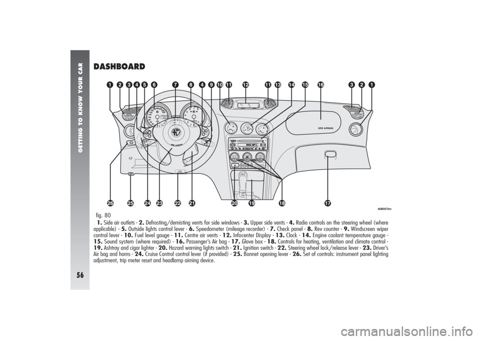
DASHBOARD1.Side air outlets - 2.Defrosting/demisting vents for side windows - 3.Upper side vents - 4.Radio controls on the steering wheel (where
applicable) - 5.Outside lights control lever - 6.Speedometer (mileage recorder) - 7.Check panel - 8.Rev counter - 9.Windscreen wiper
control lever - 10.Fuel level gauge - 11.Centre air vents - 12.Infocenter Display - 13.Clock - 14.Engine coolant temperature gauge -
15.Sound system (where required) - 16.Passenger’s Air bag - 17.Glove box - 18.Controls for heating, ventilation and climate control -
19.Ashtray and cigar lighter - 20.Hazard warning lights switch - 21.Ignition switch - 22.Steering wheel lock/release lever - 23.Driver’s
Air bag and horns - 24.Cruise Control control lever (if provided) - 25.Bonnet opening lever - 26.Set of controls: instrument panel lighting
adjustment, trip meter reset and headlamp aiming device.fig. 80
A0B0570m
Page 59 of 357
GETTING TO KNOW YOUR CAR57
INSTRUMENT CLUSTERfig. 81 - T.SPARK versions
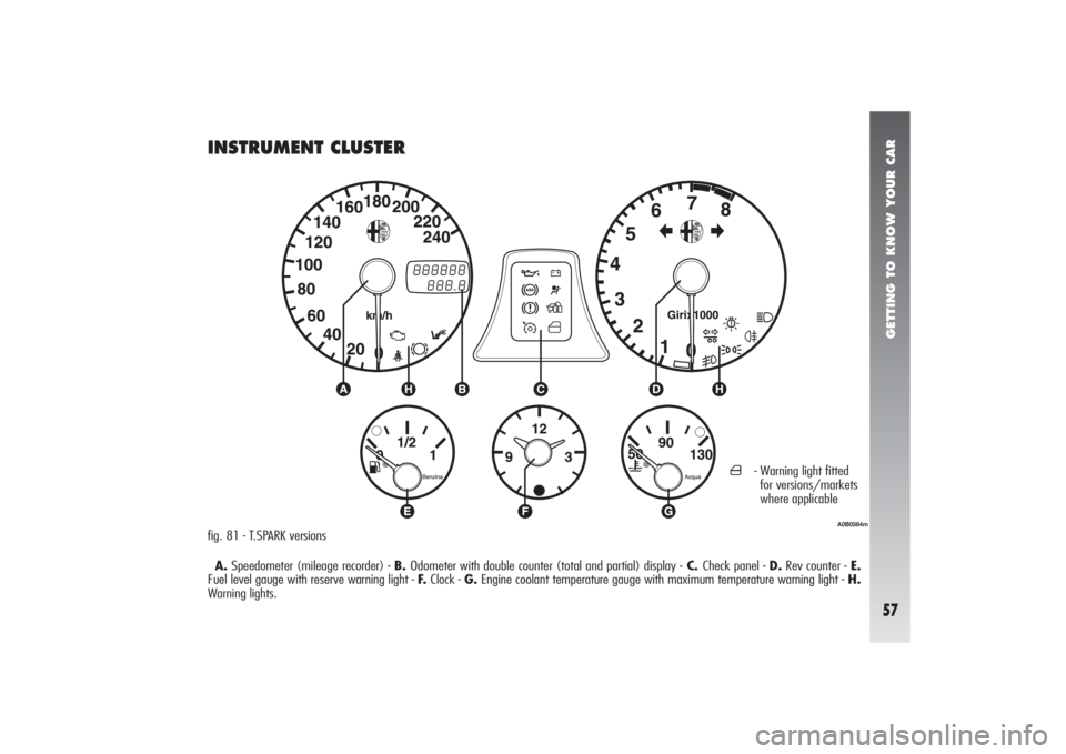
A.Speedometer (mileage recorder) - B. Odometer with double counter (total and partial) display -C. Check panel - D.Rev counter - E.
Fuel level gauge with reserve warning light - F.Clock - G.Engine coolant temperature gauge with maximum temperature warning light - H.
Warning lights.
A0B0584m
´
- Warning light fitted
for versions/markets
where applicable
Page 137 of 357

GETTING TO KNOW YOUR CAR
135
ADDITIONAL HEATER(JTD engines) (for versions/
markets where applicable)
The car is equipped with an additional
heater (not programmable) which supports
the engine during cold or winter weather
to quickly reach a comfortable temperature
inside the passenger compartment.
The heater operates with the engine run-
ning when the outside temperature is below
20°C and the engine has not yet reached
normal operating temperature.
HAZARD WARNING LIGHTS(fig. 116)
They are switched on by pressing button
(A), regardless of the position of the igni-
tion key.
When the hazard warning lights are
switched on, the switch itself begins to flash
together with the direction indicator warn-
ing lights and the emergency indicator on
the instrument panel. This functions is
switched off by pressing the button again.
CONTROLSTAILGATE OPENING
(fig. 115)
To open the boot pull the lever (A) at the
side of the driver’s seat.
fig. 115
A0B0042m
fig. 116
A0B0036m
Do not operate the boot re-
lease lever with the car on
the move.
WARNING
Use of the hazard warning
lights is ruled by the High-
way Code of the country in which
the car is used. Observe regula-
tions.
WARNING
Page 138 of 357
GETTING TO KNOW YOUR CAR
136
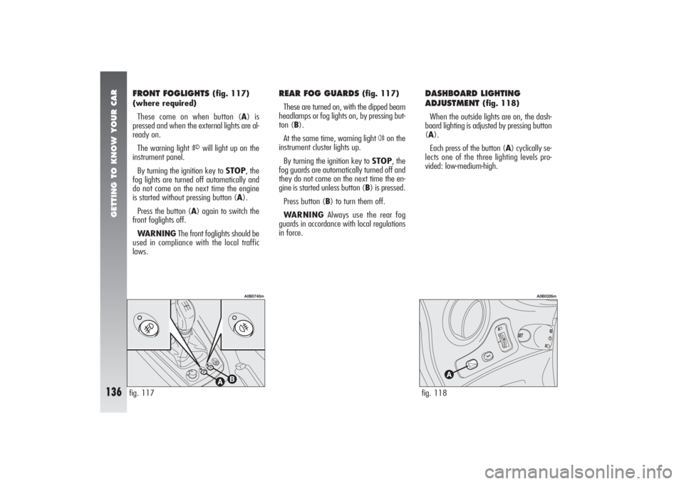
DASHBOARD LIGHTING
ADJUSTMENT
(fig. 118)
When the outside lights are on, the dash-
board lighting is adjusted by pressing button
(A).
Each press of the button (A) cyclically se-
lects one of the three lighting levels pro-
vided: low-medium-high.
FRONT FOGLIGHTS
(fig. 117)
(where required)
These come on when button (A) is
pressed and when the external lights are al-
ready on.
The warning light
5
will light up on the
instrument panel.
By turning the ignition key to STOP, the
fog lights are turned off automatically and
do not come on the next time the engine
is started without pressing button (A).
Press the button (A) again to switch the
front foglights off.
WARNINGThe front foglights should be
used in compliance with the local traffic
laws.
REAR FOG GUARDS
(fig. 117)
These are turned on, with the dipped beam
headlamps or fog lights on, by pressing but-
ton (B).
At the same time, warning light
4
on the
instrument cluster lights up.
By turning the ignition key to STOP, the
fog guards are automatically turned off and
they do not come on the next time the en-
gine is started unless button (B) is pressed.
Press button (B) to turn them off.
WARNINGAlways use the rear fog
guards in accordance with local regulations
in force.
fig. 117
A0B0740m
fig. 118
A0B0326m
Page 140 of 357

GETTING TO KNOW YOUR CAR
138
HEADLIGHT CORRECTOR (fig. 121)
If the car is fitted with xenon headlights,
beam aiming is electronic and therefore con-
trol (A) on the mask near the steering col-
umn is not present.
The headlights should be aimed correctly
depending on the vehicle load.
The control (A) on the plate at the side of
the steering column can be moved to four
positions corresponding to the vehicle loads
given below:
position 0: 1 or 2 people occupying front
seats, full fuel tank, on-board equipment pre-
sent;
position 1: 5 people on-board;fig. 121
A0B0240m
HAND BRAKE
(fig. 122)
The hand brake lever is located between
the two front seats.
To operate the brake when the vehicle is
“stationary”, pull the lever (A) upwards un-
til the required braking action is obtained.
When the ignition key is in the MARpo-
sition, the
x
warning light will come on on
the instrument panel.
fig. 122
A0B0288m
position 2: 5 people on-board, luggage
compartment full (50 kg approximately);
position 3: Driver and 300 kg in luggage
compartment.
Check the positioning of
the headlight beams every
time you change the load to be car-
ried.
WARNING
Page 141 of 357

GETTING TO KNOW YOUR CAR
139
To release the hand brake:
– slightly lift the lever (A) and press the
release button (B);
– holding the button down lower the lever.
The
x
warning light on the instrument
panel will go out.
To prevent the car from moving acciden-
tally, keep the brake pedal pressed when
engaging the handbrake.WARNINGThe handbrake lever (A) is
fitted with a safety device which prevents
the brake from being released when, if the
lever is pulled, button (B) is pressed. There-
fore, to release the brake, in addition to
pressing button (B), it is also necessary to
pull lever (A) further upwards to release the
safety device, then lower the lever com-
pletely
GEARSHIFT LEVER
(fig. 123)
Depending on the versions the car is fitted
with a five or six speed mechanical gearbox
(see “Technical specifications” chapter).
The position of the individual gears is
shown by the pictogram on the gearshift
lever knob.
When changing gear, always fully depress
the clutch pedal. Before engaging reverse
gear (R) wait for the car to be stationary.
fig. 123
A0B0290m
The wheels should be
locked after a few clicks of
the hand brake. If this does not oc-
cur, contact Alfa Romeo Authorized
Services to have the hand brake
adjusted.
WARNING
Page 171 of 357

GETTING TO KNOW YOUR CAR
169
fig. 158
A0B0247m
EMERGENCY OPERATIONIf the electrical control device does not
work, the sunroof can be opened manually
as follows:
– apply leverage to the points indicated
by the arrows and remove the plate with
switch (D-fig. 159);
– use the outfit screwdriver or the special
wrench (B-fig. 160) supplied for the ver-
sions / market where provided, and located
in the object holder drawer, push on and turn
the sunroof control bushing (C-fig. 160)
clockwise to open it and anti-clockwise to
close it. WARNINGAt the end of the operation,
before removing the screwdriver or the
wrench, it is necessary to turn it by half a
turn in the direction opposite to that used,
until a click is felt.
LUGGAGE
COMPARTMENTThe boot lid can be opened from outside
the vehicle (pressing the button on the key)
and from inside the vehicle.
WARNINGIf the boot is not properly
shut, the warning light
´
will come on on
the instrument panel or (where applicable)
on the Infocenter display (together with rel-
evant message).
fig. 159
A0B0246m
fig. 160
A0B0245m