fuse Alfa Romeo 156 2007 Owner handbook (in English)
[x] Cancel search | Manufacturer: ALFA ROMEO, Model Year: 2007, Model line: 156, Model: Alfa Romeo 156 2007Pages: 357, PDF Size: 5.04 MB
Page 241 of 357
IN AN EMERGENCY
239
69
69
69
69
71
71
69
71
69
69
69
69
72
69
69
69
69
69
69
71 10
11
13
5
4
5
3
7
15
13
15
9
1
4
12
2
15
12
12
10
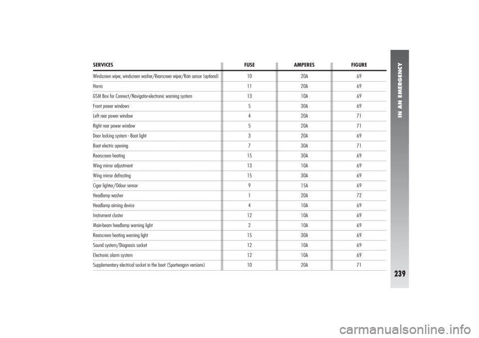
SERVICES FUSE AMPERES FIGUREWindscreen wiper, windscreen washer/Rearscreen wiper/Rain sensor (optional)HornsGSM Box for Connect/Navigator-electronic warning systemFront power windowsLeft rear power windowRight rear power windowDoor locking system - Boot lightBoot electric openingRearscreen heatingWing mirror adjustmentWing mirror defrostingCigar lighter/Odour sensorHeadlamp washerHeadlamp aiming deviceInstrument clusterMain-beam headlamp warning lightRearscreen heating warning lightSound system/Diagnosis socketElectronic alarm system Supplementary electrical socket in the boot (Sportwagon versions)20A
20A
10A
30A
20A
20A
20A
30A
30A
10A
30A
15A
20A
10A
10A
10A
30A
10A
10A
20A
Page 242 of 357
IN AN EMERGENCY
240
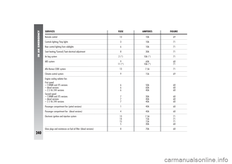
Remote controlControls lighting/Stop lightsRear control lighting from sidelightsSeat heating/Sunroof/Seat electrical adjustmentAir bag system
ABS systemAlfa Romeo CODE systemClimate control system
Engine cooling radiator fan:
First speed
– T.SPARK and JTS versions
– diesel versions
– 2.5 V6 24V versions
Second speed
– T.SPARK and JTS versions
– diesel versions– 2.5 V6 24V versionsPassenger compartment fan (petrol versions)Passenger compartment fan (diesel versions)
Electronic ignition and injection system Glow plugs and resistances on fuel oil filter (diesel versions)69
71
71
71
71
68
71
71
69
68
68
68
68
68
68
68
68
71
71
71
68
68 10A
10A
10A
30A
10A (*)
60A
10A (*)
7.5A
15A
50A
60A
40A
30A
40A
40A
40A
40A
7.5A
15A
15A
30A
70A 13
3
6
8
2 (*)
9
11 (*)
13
9
6
6
6
7
7
7
1
4
13
14
15
5
8SERVICES FUSE AMPERES FIGURE
Page 243 of 357
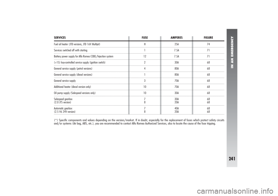
Fuel oil heater (JTD versions, JTD 16V Multijet)Services switched off with startingBattery power supply for Alfa Romeo CODE/Injection system(+15) key-controlled service supply (ignition switch)General service supply (petrol versions)General service supply (diesel versions)General service supplyAdditional heater (diesel version only)Oil pump supply (Selespeed versions only)
Selespeed gearbox(2.0 JTS version)
Automatic gearbox(2.5 V6 24V version)(*) Specific components and values depending on the version/market. If in doubt, especially for the replacement of fuses which protect safety circuits
and/or systems (Air bag, ABS, etc.), you are recommended to contact Alfa Romeo Authorized Services, also to locate the cause of the fuse tripping.
IN AN EMERGENCY
241
74
71
71
68
68
68
68
68
68
68
68
68
68 25A
7.5A
7.5A
30A
80A
80A
70A
70A
30A
30A
20A
40A
20A H
1
12
2
4
1
3
10
10
7
8
7
8
SERVICES FUSE AMPERES FIGURE
Page 256 of 357
CAR MAINTENANCE
254
fig. fig. fig. 2 - 2.0 JTS version
A0B00436m
fig. 1 - 1.6 T.SPARK, 1.8 T.SPARK versions
A0B00174m
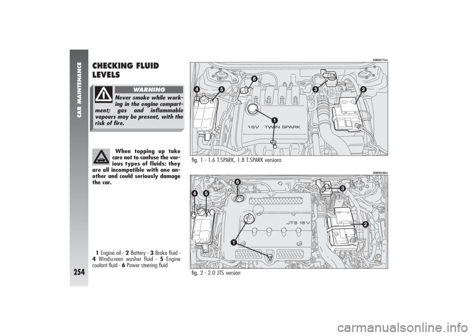
CHECKING FLUID
LEVELS1Engine oil - 2Battery - 3Brake fluid -
4Windscreen washer fluid - 5Engine
coolant fluid - 6Power steering fluid When topping up take
care not to confuse the var-
ious types of fluids: they
are all incompatible with one an-
other and could seriously damage
the car.
Never smoke while work-
ing in the engine compart-
ment; gas and inflammable
vapours may be present, with the
risk of fire.
WARNING
Page 300 of 357
ALFA 156 SPORTWAGON
298
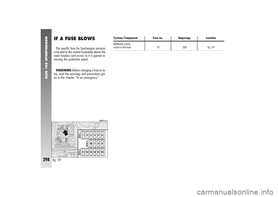
System/Component Fuse no. Amperage Location
Additional current socket in the boot10 20Afig. 59
fig. 59
A0B0141m
IF A FUSE BLOWSThe specific fuse for Sportwagon versions
is located in the central fuseholder above the
main fusebox and access to it is gained re-
moving the protective panel.
WARNINGBefore changing a fuse or re-
lay, read the warnings and precautions giv-
en in the chapter “In an emergency”.
Page 331 of 357
ALPHABETICAL INDEX
329
Front light units
– bulb arrangement................... 220
Front roof light ............................ 162
– changing bulbs ...................... 230
Front seats .................................. 21
– adjustments .......................... 21
– centre armrest ....................... 22
– electric heating ..................... 22
– headrests .............................. 23
– rear pockets .......................... 23
Fuel
– consumption ......................... 322
– emergency flap opening
device ............................ 186-292
– fuel cap ............................... 186
– fuel flap................................ 137
– inertial fuel cut-off switch ........ 137
– level gauge and reserve
warning light ......................... 62
– refilling ................................ 319
– refuelling ........................ 185-292
– specifications ......................... 319
Fuel reserve ......................... 62-319
Fuel supply (technical data)........... 303
Fuel tank (capacity) .................... 319
Fuses and relays
– fuse summary table................ 238– fuses above the main fusebox.. 236
– fuses and relays accessible from
the glovebox ......................... 236
– fuses and relays in engine bay . 236
– fuses and relays in the main
fusebox ................................ 235
– generalities and cautions ........ 234
– list of protected devices .......... 238
– specific fuses for Sportwagon
versions ................................ 299
G
earshift lever ........................... 139
Getting to know your car.... 6
Glovebox light
– changing bulbs ..................... 232
Grab handles .......................... 161-292
H
andbrake lever......................... 138
Hazard lights
– switching on ......................... 135
Headlight aiming device
(corrector)................................ 138
Headlight washer ................... 52-274
Headlights
– beam adjustment .................. 138
– beam adjustment abroad ........ 177
– bulb replacement ............. 217-220– compensation for tilt............... 175
– gas discharge headlights ......... 176
Headrests
– front .................................... 23
– rear ............................... 24-279
Horn .......................................... 56
Identification data ....................... 299
Identification labels ...................... 300
Ignition device and steering lock 17-18
In an emergency.................... 205
In the event of a puncture ....... 207-294
– changing a wheel................... 209
– FIX&GO (quick tyre repair kit) . 212
– general instructions ................ 207
In the event of an accident ............ 246
– first aid kit ............................ 247
– if anybody is injured .............. 246
Inertial fuel cut-off switch .............. 137
Infocenter ................................... 64
– access to main menu screen .... 72
– control buttons ...................... 66
– date setting/time setting ........ 76
– default value reset ................. 85
– display ................................. 64
– display contrast adjustment ..... 84
Page 354 of 357
RIGHT HAND DRIVE VERSION
352
Q-SYSTEM
AUTOMATIC
GEARBOXBelow you will find the more significant
particulars of right-hand drive versions.
WARNINGAs the differences are only
formal, due to the specular position of the
controls, as far as functioning is concerned,
please refer to the descriptions given for left-
hand drive versions.
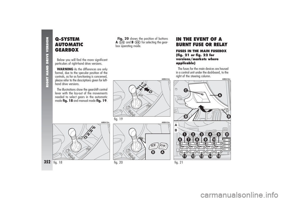
The illustrations show the gearshift control
lever with the lay-out of the movements
needed to select gears in the automatic
mode fig. 18and manual mode fig. 19.Fig. 20shows the position of buttons
A and B for selecting the gear-
box operating mode.
ICE
C/S
IN THE EVENT OF ABURNT FUSE OR RELAYFUSES IN THE MAIN FUSEBOX
(fig. 21 or fig. 22 for
versions/markets where
applicable)The fuses for the main devices are housed
in a control unit under the dashboard, to the
right of the steering column.
fig. 18
A0B0413m
fig. 20
A0B0415m
fig. 19
A0B0414m
fig. 21
A0B0416m
Page 355 of 357
RIGHT HAND DRIVE VERSION
353
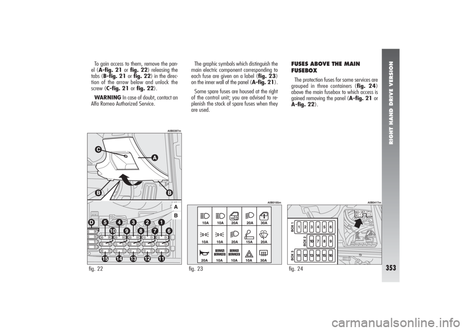
To gain access to them, remove the pan-
el (A-fig. 21 orfig. 22) releasing the
tabs (B-fig. 21 orfig. 22) in the direc-
tion of the arrow below and unlock the
screw (C-fig. 21 orfig. 22).
WARNINGIn case of doubt, contact an
Alfa Romeo Authorized Service.The graphic symbols which distinguish the
main electric component corresponding to
each fuse are given on a label (fig. 23)
on the inner wall of the panel (A-fig. 21).
Some spare fuses are housed at the right
of the control unit; you are advised to re-
plenish the stock of spare fuses when they
are used.
FUSES ABOVE THE MAIN
FUSEBOXThe protection fuses for some services are
grouped in three containers (fig. 24)
above the main fusebox to which access is
gained removing the panel (A-fig. 21 or
A-fig. 22).
fig. 23
A0B0185m
fig. 24
A0B0417m
fig. 22
A0B0397m