technical specifications Alfa Romeo 159 2006 Owner handbook (in English)
[x] Cancel search | Manufacturer: ALFA ROMEO, Model Year: 2006, Model line: 159, Model: Alfa Romeo 159 2006Pages: 299, PDF Size: 4.64 MB
Page 97 of 299

95
SAFETY
DEVICES
WARNING
LIGHTS AND
MESSAGES
IN AN
EMERGENCY
CAR
MAINTENANCE
TECHNICAL
SPECIFICATIONS
INDEX
CORRECT USE
OF THE CAR
DASHBOARD
AND
CONTROLS
ANTI-CRUSHING SAFETY
SYSTEM
The anti-crushing safety system fitted on
the front curtain outline is active during
horizontal closing (front edge) and ver-
tical closing of the panel (rear edge) and
it will cut in when it finds an obstacle
(e.g.: finger, hand, etc …), thus guar-
anteeing sunroof reversal for a short sec-
tion.
When an obstacle is found, sunroof
stroke is stopped immediately and its
stroke is reversed to the preset position:
❒during horizontal closing it is active
along the whole stroke of the sunroof
and when it finds an obstacle on the
front side of the pane it guarantees
a 10 cm stroke reversal;
❒during vertical closing it is active
along the whole stroke of the sunroof
and when it finds an obstacle on the
rear side of the pane it guarantees
stroke reversal.
EMERGENCY OPERATION
In a emergency or during servicing (with-
out power supply), the sunroof can be
operated manually; proceed as follows:
❒press the light notches to release the
clips and remove the front ceiling light
A-fig. 89.
❒fit the setscrew wrench into the prop-
er slot B;
❒turn the key to open or to close (ac-
cording to rotation direction) the sun-
roof.
SUNROOF INITIALISATION
PROCEDURE
After disconnecting the battery or failing
the protection fuse, the sunroof shall be
“initialised” again, proceed as follows:
❒turn selector fully leftwards (counter-
clokwise);
❒press and keep pressed selector until
sunroof locking;
❒release selector;
❒press selector again within 3 seconds,
and keep it pressed;
❒a few seconds after the sunroof will
move automatically (during this stage
keep on pressing the knob);
❒initialisation will end when the sun-
roof stops. Release selector.
A0E0187mfig. 89
Page 98 of 299

96
SAFETY
DEVICES
WARNING
LIGHTS AND
MESSAGES
IN AN
EMERGENCY
CAR
MAINTENANCE
TECHNICAL
SPECIFICATIONS
INDEX
CORRECT USE
OF THE CAR
DASHBOARD
AND
CONTROLS
With key removed the led will turn off
after about 2 minutes.
When doors are unlocked the led is off;
pressing the button will lock all the
doors. Central door locking will only take
place if all doors are perfectly closed.
DOORS
CENTRAL DOOR LOCKING/
UNLOCKING SYSTEM
Door locking from the outside
With the doors closed, press the elec-
tronic key button
Áor fit and turn the
metal insert (inside the key) into the
lock of the driver’s door. Central door
locking can only be activated if all the
doors are closed. If one or more doors
are open after pressing the electronic
key button
Áthe direction indicators and
the driver’s door led will flash fast for
about 3 seconds.
If one or more doors are open by turning
the metal insert of the electronic key, on-
ly the driver’s door led will flash fast for
about 3 seconds. If the doors are closed
but the tailgate is open, central locking
is actuated: the direction indicators (only
for locking performed by pressing button
Á) and the driver’s door led will flash fast
for about 3 seconds.
A0E0025mfig. 90
Through the “Setup menu” (or the Ra-
dionavigation system for certain versions)
it is possible to activate the function that
enables to unlock only the driver’s door
lock by pressing the electronic key button
Ë(see paragraph “Reconfigurable mul-
tifunction display” in this section).
With this function on (ON) it is howev-
er possible to unlock the other doors by
pressing button
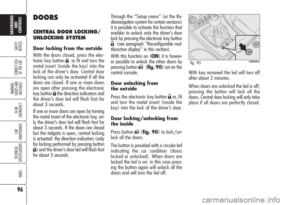
q(fig. 90) set on the
central console.
Door unlocking from
the outside
Press the electronic key button
Ëor, fit
and turn the metal insert (inside the
key) into the lock of the driver’s door.
Door locking/unlocking from
the inside
Press button
q(fig. 90) to lock/un-
lock all the doors.
The button is provided with a circular led
indicating the car condition (doors
locked or unlocked). When doors are
locked the led is on: in this case press-
ing the button again will unlock all the
doors and will turn the led off.
Page 99 of 299

97
SAFETY
DEVICES
WARNING
LIGHTS AND
MESSAGES
IN AN
EMERGENCY
CAR
MAINTENANCE
TECHNICAL
SPECIFICATIONS
INDEX
CORRECT USE
OF THE CAR
DASHBOARD
AND
CONTROLS
CHILD LOCK
Rear doors are fitted with a locking de-
vicefig. 91 that inhibits door open-
ing from the inside.
This device can be engaged/disengaged
(by the metal insert of the key) only
with doors open:
❒position 1: engaged (door locked);
❒position 2: disengaged (door can
be opened from the inside).IMPORTANTEach device acts only
on the relevant door.
IMPORTANT Always use this device
when transporting children.
IMPORTANTAfter engaging the child
lock on both rear doors, check for prop-
er engagement by trying to open a rear
door with the internal handle. Button
qis disabled after door locking
carried out by operating the remote con-
trol, the driver's door revolving plug, or
by automatic door locking after about
2.5 minutes and it will be enabled again
after door unlocking carried out by press-
ing the key button
Ë, by turning the
metal insert of the key into the driver's
door lock or by fitting the key into the
ignition device.
IMPORTANT With central locking sys-
tem on, pulling the internal door handle
will unlock all the doors. Lacking pow-
er (blown fuse, battery disconnected,
etc.) it is however possible to lock the
doors manually.
A0E0155mfig. 91
Page 100 of 299

Doorknobs can be realigned (only after
recharging the battery) as follows:
❒pressing the electronic key button Ë;
❒pressing door locking/unlocking but-
ton
q;
❒opening with the key in front door re-
volving plug;
❒pulling internal door handle.IMPORTANTAs concerns rear doors,
with child lock device on and the previ-
ously described locking active, operat-
ing the internal door handle will not
open the door but will only realign door-
knobs; to open the door pull the exter-
nal door handle. Emergency locking will
not disable central door locking/un-
locking button
q.
IMPORTANTAfter disconnecting the
battery or failing the protection fuse, the
door locking/unlocking mechanism shall
be “initialised” again, proceed as fol-
lows:
❒lock the doors;
❒press the remote control button Áor
the button
qon the central console;
❒press the remote control button Ëor
the button
qon the central console.
DOOR LOCKING WITH RUN
DOWN BATTERY
If the car battery is run down, to lock
the doors proceed as described in the
following points.
Right front door
Proceed as follows:
❒remove the protection plug on the
door;
❒fit the electronic key metal insert in-
toA-fig. 92;
❒turn the key clockwise (counter-clock-
wise for right-hand drive versions);
❒remove the key from A-fig. 92and
then efit the plug on the door.
98
SAFETY
DEVICES
WARNING
LIGHTS AND
MESSAGES
IN AN
EMERGENCY
CAR
MAINTENANCE
TECHNICAL
SPECIFICATIONS
INDEX
CORRECT USE
OF THE CAR
DASHBOARD
AND
CONTROLS
A0E0237mfig. 92
Page 101 of 299

99
SAFETY
DEVICES
WARNING
LIGHTS AND
MESSAGES
IN AN
EMERGENCY
CAR
MAINTENANCE
TECHNICAL
SPECIFICATIONS
INDEX
CORRECT USE
OF THE CAR
DASHBOARD
AND
CONTROLS
In this case it is necessary to carry out
system restore procedure as follows:
❒open the windows;
or
❒remove and then refit the key into the
ignition device.
If no malfunction is present, the window
returns to its normal operation automat-
ically. In the event of a failure see section
“Warning lights and messages”.
Windows and sunroof
opening/closing by the
electronic key
(where provided)
By the metal insert of the key
On all versions:
❒turning clockwise the metal insert of
the key into the driver's door re-
volving plug will open all the win-
dows and the sunroof (where pro-
vided) at the same time.
❒turning counterclockwise the metal
insert of the key into the driver's
door revolving plug will close all the
windows and the sunroof (where
provided) at the same time.By remote control
On all versions, keep button
Ëpressed
for over 2 seconds to open all the win-
dows and the sunroof (where provided)
at the same time.
On versions provided with 4 power win-
dow, keep button
Ápressed for over 2
seconds to close all the windows and
the sunroof (where provided) at the
same time.
POWER WINDOWS
Versions with 2 front power windows
are fitted with automatic window open-
ing/closing only on the driver’s side.
Versions with 4 power windows are fit-
ted with automatic window opening/
closing on all doors. These versions are
fitted with anti-crushing safety device to
detect the presence of an obstacle in the
window closing stroke. If an obstacle
is detected, the safety system will stop
window closing and, according to win-
dow position, will also reverse window
stroke.
This system is particularly useful when
children operate the windows inadver-
tently and make it possible to
close/open the windows using the re-
mote control when leaving the car.
IMPORTANTIn the event the anti-
crushing function is activated 5 times in
only 1 minute or in the event of a fail-
ure, the system will automatically enter
the “recovery” mode (self-protection).
This condition is pointed out by the fact
that, in the closing stroke, the windows
goes up in jerks.
The system complies
with the forthcoming
Standard 2000/4/ EC
concerning the safety of pas-
sengers leaning out of the pas-
senger compartment.
Page 102 of 299

100
SAFETY
DEVICES
WARNING
LIGHTS AND
MESSAGES
IN AN
EMERGENCY
CAR
MAINTENANCE
TECHNICAL
SPECIFICATIONS
INDEX
CORRECT USE
OF THE CAR
DASHBOARD
AND
CONTROLS
C(where provided) – rear left window
opening/closing; “automatic continu-
ous” mode operation during window
opening/closing;
D(where provided) – rear right win-
dow opening/closing; “automatic con-
tinuous” mode operation just during win-
dow opening;
E(where provided) – rear power win-
dow enabling/disabling controls (when
rear power window controls are dis-
abled, the led on button Ewill turn on
and disabled controls will turn off).
Press buttons A,B,CorDto open/
close the required window.
Pressing briefly one of the buttons the
window “jerks” whereas a prolonged
pressing makes the window opening or
closing in “automatic continuous”
mode.
Pressing button A,B,CorDagain will
stop the window in the required posi-
tion.Front passenger door/
rear doors
Front passenger door and, on certain
versions, rear doors are fitted with but-
ton panels controlling opening/closing
of the corresponding window.
CONTROLS
Driver side
On the driver’s door panel are set the
buttonsfig. 93 for controlling, with
electronic key fitted into the ignition de-
vice:
A– front left window opening/closing;
window opening or closing in “auto-
matic continuous” mode;
B– front right window opening/clos-
ing; window opening or closing in “au-
tomatic continuous” mode (only ver-
sions with 4 power windows);
A0E0051mfig. 93
Improper use of the
power windows can be
dangerous. Before and
during its operation ensure that
any passengers are not at risk
from the moving glass either by
personal objects getting caught
in the mechanism or by being in-
jured by it directly. Always re-
move the ignition key when
getting out of the car to prevent
the power windows being op-
erated accidentally and consti-
tuting a danger to the passen-
gers in the car.
Page 103 of 299

101
SAFETY
DEVICES
WARNING
LIGHTS AND
MESSAGES
IN AN
EMERGENCY
CAR
MAINTENANCE
TECHNICAL
SPECIFICATIONS
INDEX
CORRECT USE
OF THE CAR
DASHBOARD
AND
CONTROLS
On certain versions, improper boot
closing is indicated by the instrument
panel warning light
´, whereas on
other versions the symbol
Rand a
message are displayed (see section
“Warning lights and messages”).
OPENING FROM
THE INSIDE
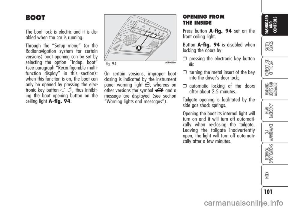
Press button A-fig. 94set on the
front ceiling light.
ButtonA-fig. 94is disabled when
locking the doors by:
❒pressing the electronic key button
Á;
❒turning the metal insert of the key
into the driver's door lock;
❒automatic locking of the doors
after about 2.5 minutes.
Tailgate opening is facilitated by the
side gas shock springs.
Opening the boot its internal light will
turn on and it will turn off automati-
cally when re-closing the tailgate.
Leaving the tailgate inadvertently
open, the light will turn off automati-
cally after a few minutes.
BOOT
The boot lock is electric and it is dis-
abled when the car is running.
Through the “Setup menu” (or the
Radionavigation system for certain
versions) boot opening can be set by
selecting the option “Indep. boot”
(see paragraph “Reconfigurable multi-
function display” in this section):
when this function is on, the boot can
only be opened by pressing the elec-
tronic key button
`, thus inhibit-
ing the boot opening button on the
ceiling light A-fig. 94.
A0E0096mfig. 94
Page 104 of 299

102
SAFETY
DEVICES
WARNING
LIGHTS AND
MESSAGES
IN AN
EMERGENCY
CAR
MAINTENANCE
TECHNICAL
SPECIFICATIONS
INDEX
CORRECT USE
OF THE CAR
DASHBOARD
AND
CONTROLS
OPENING BY REMOTE
CONTROL
Press the electronic key button `.
Opening is indicated by double flashing
of direction indicators.
Opening the boot with alarm (where
provided) on will cause the following:
❒volumetric protection deactivation;
❒anti-raising protection deactivation;
❒tailgate monitoring sensor.
Re-closing the tailgate will restore all the
above functions and direction indicators
will turn on for about 1 second. Emergency opening of the
boot from the passenger
compartment
If the battery is disconnected, the boot
can be opened by pulling the lever A-
fig. 95set under the rear left seat.
Refit the handle under the cushion after
using it.
A0E0228mfig. 95
IMPORTANTAfter disconnecting the
battery or failing the protection fuse, the
tailgate locking/unlocking mechanism
shall be “initialised” again, proceed as
follows:
❒lock the doors and the tailgate;
❒press the remote control button Áor
the button
qon the central console;
❒press the remote control button Ëor
the button
qon the central console.
Page 105 of 299

103
SAFETY
DEVICES
WARNING
LIGHTS AND
MESSAGES
IN AN
EMERGENCY
CAR
MAINTENANCE
TECHNICAL
SPECIFICATIONS
INDEX
CORRECT USE
OF THE CAR
DASHBOARD
AND
CONTROLS
TAILGATE CLOSING
Lower the tailgate pressing the lock un-
til hearing the locking click.
IMPORTANT If the option for ”Indep.
boot” is on, before closing the boot,
check whether you have with you the
ignition key since the boot will be locked
automatically.
The addition of objects
(speakers, spoilers, etc.)
on the rear shelf or boot
lid, except those envisaged by
the manufacturer, may prevent
the gas filled struts at the sides
of the boot from working prop-
erly.
When using the boot,
make sure the loads do
not exceed the permitted
weight (see “Technical specifi-
cations” chapter). Also make
sure the items in the boot are
arranged properly to prevent
them being thrown forwards
and injuring passengers should
you brake sharply.
WARNING
Never travel with ob-
jects on the rear shelf
to prevent them being thrown
forwards and injuring passen-
gers in case of accident or
sharp braking.
WARNING
EXTENDING THE BOOT
(where provided)
To extend the boot proceed as follows:
❒remove rear head restraints;
❒turn head restraints by 180° and fit
them into their seat;
❒move aside the seat belt, check that
it is not twisted;
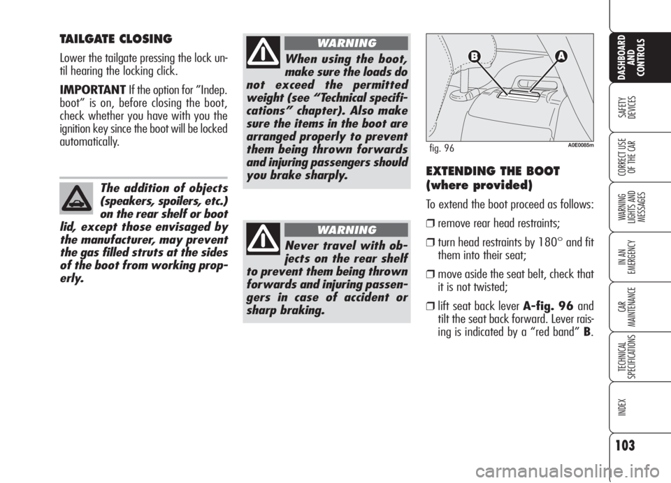
❒lift seat back lever A-fig. 96 and
tilt the seat back forward. Lever rais-
ing is indicated by a “red band” B.
A0E0085mfig. 96
Page 106 of 299

104
SAFETY
DEVICES
WARNING
LIGHTS AND
MESSAGES
IN AN
EMERGENCY
CAR
MAINTENANCE
TECHNICAL
SPECIFICATIONS
INDEX
CORRECT USE
OF THE CAR
DASHBOARD
AND
CONTROLS
ANCHORING THE LOAD
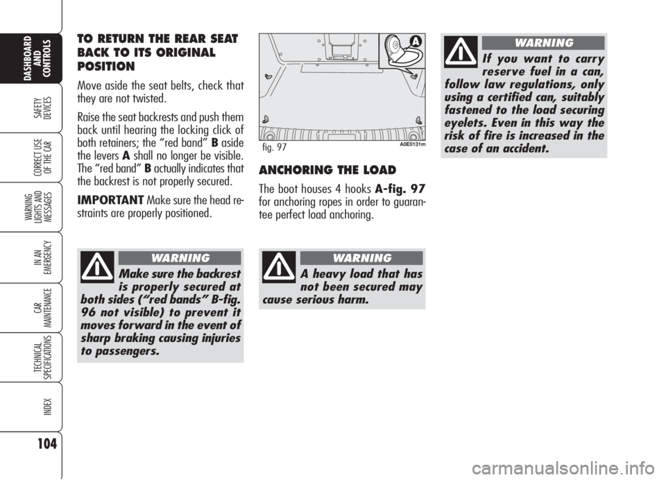
The boot houses 4 hooks A-fig. 97
for anchoring ropes in order to guaran-
tee perfect load anchoring.
A0E0131mfig. 97
A heavy load that has
not been secured may
cause serious harm.
WARNING
If you want to carry
reserve fuel in a can,
follow law regulations, only
using a certified can, suitably
fastened to the load securing
eyelets. Even in this way the
risk of fire is increased in the
case of an accident.
WARNINGTO RETURN THE REAR SEAT
BACK TO ITS ORIGINAL
POSITION
Move aside the seat belts, check that
they are not twisted.
Raise the seat backrests and push them
back until hearing the locking click of
both retainers; the “red band” Baside
the levers Ashall no longer be visible.
The “red band” Bactually indicates that
the backrest is not properly secured.
IMPORTANTMake sure the head re-
straints are properly positioned.
Make sure the backrest
is properly secured at
both sides (“red bands” B-fig.
96 not visible) to prevent it
moves forward in the event of
sharp braking causing injuries
to passengers.
WARNING