boot Alfa Romeo 159 2006 Owner handbook (in English)
[x] Cancel search | Manufacturer: ALFA ROMEO, Model Year: 2006, Model line: 159, Model: Alfa Romeo 159 2006Pages: 299, PDF Size: 4.64 MB
Page 106 of 299
104
SAFETY
DEVICES
WARNING
LIGHTS AND
MESSAGES
IN AN
EMERGENCY
CAR
MAINTENANCE
TECHNICAL
SPECIFICATIONS
INDEX
CORRECT USE
OF THE CAR
DASHBOARD
AND
CONTROLS
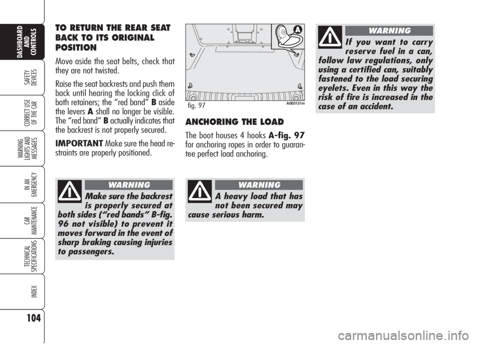
ANCHORING THE LOAD
The boot houses 4 hooks A-fig. 97
for anchoring ropes in order to guaran-
tee perfect load anchoring.
A0E0131mfig. 97
A heavy load that has
not been secured may
cause serious harm.
WARNING
If you want to carry
reserve fuel in a can,
follow law regulations, only
using a certified can, suitably
fastened to the load securing
eyelets. Even in this way the
risk of fire is increased in the
case of an accident.
WARNINGTO RETURN THE REAR SEAT
BACK TO ITS ORIGINAL
POSITION
Move aside the seat belts, check that
they are not twisted.
Raise the seat backrests and push them
back until hearing the locking click of
both retainers; the “red band” Baside
the levers Ashall no longer be visible.
The “red band” Bactually indicates that
the backrest is not properly secured.
IMPORTANTMake sure the head re-
straints are properly positioned.
Make sure the backrest
is properly secured at
both sides (“red bands” B-fig.
96 not visible) to prevent it
moves forward in the event of
sharp braking causing injuries
to passengers.
WARNING
Page 109 of 299
107
SAFETY
DEVICES
WARNING
LIGHTS AND
MESSAGES
IN AN
EMERGENCY
CAR
MAINTENANCE
TECHNICAL
SPECIFICATIONS
INDEX
CORRECT USE
OF THE CAR
DASHBOARD
AND
CONTROLS
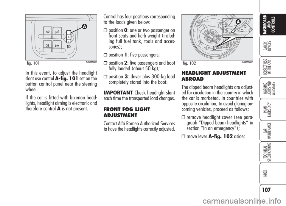
In this event, to adjust the headlight
slant use control A-fig. 101set on the
button control panel near the steering
wheel.
If the car is fitted with bixenon head-
lights, headlight aiming is electronic and
therefore control Ais not present.Control has four positions corresponding
to the loads given below:
❒position0: one or two passenger on
front seats and kerb weight (includ-
ing full fuel tank, tools and acces-
sories);
❒position1: five passengers;
❒position2: five passengers and boot
fully loaded (about 50 kg);
❒position3: driver plus 300 kg load
completely stored into the boot.
IMPORTANT Check headlight slant
each time the transported load changes.
FRONT FOG LIGHT
ADJUSTMENT
Contact Alfa Romeo Authorized Services
to have the headlights correctly adjusted.
A0E0226mfig. 101
HEADLIGHT ADJUSTMENT
ABROAD
The dipped beam headlights are adjust-
ed for circulation in the country in which
the car is marketed. In countries with
opposite circulation, to avoid glaring on-
coming vehicles, proceed as follows:
❒remove headlight cover (see para-
graph “Dipped beam headlights” in
section “In an emergency”);
❒move lever A-fig. 102aside;
A0E0050mfig. 102
Page 128 of 299

126
SAFETY
DEVICES
WARNING
LIGHTS AND
MESSAGES
IN AN
EMERGENCY
CAR
MAINTENANCE
TECHNICAL
SPECIFICATIONS
INDEX
CORRECT USE
OF THE CAR
DASHBOARD
AND
CONTROLS
EMERGENCY OPENING OF
THE FUEL FILLER CAP
In case of failure, the fuel filler cap can
be opened by pulling string set on the
right side of the boot fig. 110.
A0E0130mfig. 110
FUEL FILLER CAP
The fuel filler cap is unlocked when cen-
tral door locking is off and it is auto-
matically locked when activating the
central door locking. To open the fuel
filler cap, operate as shown by the ar-
row infig. 108.
The fuel filler cap is A-fig. 109 fitted
with an antiloss device Bwhich fastens
it to the flap Cso it cannot be mislaid.
A0E0159mfig. 108A0E0160mfig. 109
Do not put naked
flames or lighted ciga-
rettes near the fuel filler hole
as there is danger of fire. Do
not bend too close to the hole
either so as not to breathe in
harmful vapours.
WARNING
When refuelling, position the cap on the
device inside the flap as shown in the
figure.
IMPORTANTThe sealing of the tank
may cause light pressurising in the tank.
A little breathing off, while slackening
the cap, is absolutely normal.
Page 159 of 299
157
SAFETY
DEVICES
WARNING
LIGHTS AND
MESSAGES
IN AN
EMERGENCY
CAR
MAINTENANCE
TECHNICAL
SPECIFICATIONS
INDEX
DASHBOARD
AND
CONTROLS
CORRECT USE
OF THE CAR
Climate control
The air conditioner is an additional load
which greatly affects the engine leading
to higher consumption. When the tem-
perature outside the car permits it, use
the air vents where possible.
Spoilers
The use of aerodynamic optional extras
which are not certified for the specific
use on the vehicle, may reduce the aero-
dynamic penetration of the vehicle and
increase consumption. Unnecessary loads
Do not travel with too much luggage
stowed in the boot. The weight of the
car (especially when driving in town)
and its trim greatly affects consumption
and stability.
Roof rack/ski rack
Remove the roof rack or the ski rack
from the roof as soon as they are no
longer used. These accessories lower air
penetration and adversely affect con-
sumption levels. When needing to car-
ry particularly voluminous objects, prefer-
ably use a trailer.
Electric devices
Use electric devices only for the amount
of time needed. Rear heated window,
additional headlights, windscreen wipers
and heater fan need a considerable
amount of energy, therefore increasing
the requirement of current increases fu-
el consumption (up to +25% in the ur-
ban cycle).CONTAINING
RUNNING COSTS
Here are some suggestions which may
help you to keep the running costs of
your car down and lower the amount of
toxic emissions released into the at-
mosphere.
GENERAL CONSIDERATIONS
Car maintenance
Have checks and adjustments carried out
in accordance with the “Service sched-
ule”.
Tyres
Check the pressure of the tyres routine-
ly at an interval of no more than 4
weeks: if the pressure is too low, con-
sumption levels increase as resistance
to rolling is higher.
Page 167 of 299
165
SAFETY
DEVICES
IN AN
EMERGENCY
CAR
MAINTENANCE
TECHNICAL
SPECIFICATIONS
INDEX
CORRECT USE
OF THE CAR
DASHBOARD
AND
CONTROLS
WARNING
LIGHTS AND
MESSAGES
W W
A A
R R
N N
I I
N N
G G
L L
I I
G G
H H
T T
S S
A A
N N
D D
M M
E E
S S
S S
A A
G G
E E
S S
LOW BRAKE FLUID/HANDBRAKE ON ..................... 167
BRAKE PAD WEAR ............................................. 167
SEAT BELTS NOT FASTENED ................................. 167
AIR BAG FAILURE................................................ 168
FRONT AIR BAGS DEACTIVATED ............................ 168
ENGINE COOLANT
HIGH TEMPERATURE ........................................... 169
ENGINE OIL HIGH TEMPERATURE .......................... 170
LOW ENGINE OIL PRESSURE/
EXHAUST OIL..................................................... 170
LOW BATTERY CHARGE ....................................... 170
INCOMPLETE DOOR LOCKING ............................... 171
BONNET OPEN ................................................... 171
BOOT OPEN....................................................... 171
INJECTION SYSTEM FAILURE/
EOBD SYSTEM FAILURE....................................... 171
CAR PROTECTION SYSTEM FAILURE/
STEERING LOCK INHIBITION................................. 172
ALARM FAILURE/BREAK-IN ATTEMPT
ELECTRONIC KEY NOT RECOGNIZED ...................... 172
POSSIBLE PRESENCE OF ICE ON THE ROAD............ 173
PRE-HEATING GLOW PLUGS/
PRE-HEATING GLOW PLUG FAILURE ....................... 173
WATER IN DIESEL FUEL FILTER ............................. 174
INERTIAL FUEL CUT-OFF
SWITCHED ON .................................................. 174
ABS SYSTEM FAILURE......................................... 175
EBD SYSTEM FAILURE......................................... 175
VDC SYSTEM .................................................... 175HILL HOLDER FAILURE ........................................ 176
ASR SYSTEM (WHEEL ANTISKID SYSTEM) ............. 176
EXTERNAL LIGHTS FAILURE .................................. 176
BRAKE LIGHTS FAILURE ....................................... 177
REAR FOGLIGHTS ............................................... 177
FRONT FOG LIGHTS ............................................ 177
SIDE/TAILLIGHTS/FOLLOW ME HOME .................. 177
DIPPED BEAM HEADLIGHTS.................................. 177
MAIN BEAM HEADLIGHTS .................................... 177
LEFT-HAND DIRECTION INDICATOR ........................ 177
RIGHT-HAND DIRECTION INDICATOR ...................... 177
LIGHT SENSOR FAILURE........................................ 178
RAIN SENSOR FAILURE......................................... 178
PARKING SENSORS FAILURE ................................ 178
FUEL RESERVE – LIMITED CRUISING RANGE .......... 178
CRUISE CONTROL .............................................. 178
DIESEL PARTICULATE FILTER CLOGGED .................. 178
ANTIPINCH SYSTEM FAILURE ............................... 179
WINDSCREEN WASHER FLUID LOW LEVEL ............. 179
SPEED LIMIT EXCEEDED ..................................... 179
T.P.M.S. SYSTEM FAILURE ................................... 179
CHECK TYRE PRESSURE ...................................... 179
LOW INFLATION PRESSURE ................................. 180
TYRE PRESSURE UNSUITABLE FOR SPEED ............. 180
Page 173 of 299

171
SAFETY
DEVICES
IN AN
EMERGENCY
CAR
MAINTENANCE
TECHNICAL
SPECIFICATIONS
INDEX
CORRECT USE
OF THE CAR
DASHBOARD
AND
CONTROLS
WARNING
LIGHTS AND
MESSAGES
BOOT OPEN
On certain versions message
and symbol
R(red) are
displayed to indicate that boot is
open.
BONNET OPEN
(where provided)
On certain versions message
and symbol
S(red) are displayed to
indicate that bonnet is open.
INJECTION SYSTEM
FAILURE (diesel
versions - amber)
EOBD SYSTEM
FAILURE
(petrol versions -
amber)
Injection system failure
Fitting the key into the ignition device
the warning light turns on, but it should
go off when the engine has started.
The warning light stays on or it turns on
when travelling to indicate a malfunc-
tion in the injection/exhaust system
with possible lack of performance, poor
driveability and high consumption.
In these conditions it is possible to con-
tinue driving without however requiring
heavy effort or high speed from the en-
gine. In any case, contact Alfa Romeo
Authorized Services as soon as possible.EOBD system failure
Under normal conditions, fitting the elec-
tronic key into the ignition device, the
warning light turns on, but it should go
off when the engine has started. This in-
dicates proper operation of the warn-
ing light.
If the warning light stays on or turns on
when travelling:
– glowing steadily (on certain ver-
sions together with the message on the
display): means a fault in the sup-
ply/ignition system which could cause
high emissions at the exhaust, possible
lack of performance, poor handling and
high consumption levels. In these con-
ditions it is possible to continue driving
without however requiring heavy effort
or high speed from the engine. Pro-
longed use of the car with the warning
light on may cause damages. Contact
Alfa Romeo Authorized Services as soon
as possible.
The warning light goes off if the fault
disappears, but it is however stored by
the system.
INCOMPLETE DOOR
LOCKING (red)
The warning light (where pro-
vided) (or symbol on the display) turns
on when one or more doors, the boot or
the bonnet (where provided) are not
properly shut.
U´
S
R
Page 191 of 299

189
SAFETY
DEVICES
WARNING
LIGHTS AND
MESSAGES
CAR
MAINTENANCE
TECHNICAL
SPECIFICATIONS
INDEX
CORRECT USE
OF THE CAR
DASHBOARD
AND
CONTROLS
IN AN
EMERGENCY
REFITTING A
NORMAL WHEEL
Following the procedure described pre-
viously, raise the car and remove the
spare wheel.
Versions with steel rims
Proceed as follows:
❒Make sure the contact surfaces be-
tween standard wheel and hub are
clean so that the fastening bolts will not
come loose;
❒Fit the standard wheel taking into ac-
count that pin B-fig. 10shall coin-
cide with one of the holes A;
❒Place the wheel cap on the wheel rim
making symbol
C, (marked inside the
wheel cap), coincide with the inflation
valvefig. 12;
❒Using the wrench provided, tighten the
fastening bolts;
❒ Lower the car and remove the jack;
❒Using the wrench provided, fully tight-
en the bolts in the sequence shown
infig. 11;
A0E0211mfig. 13
Versions with alloy rims
Proceed as follows:
❒tighten pin A-fig. 13in one of the
holes of the wheel hub fastening
bolts;
❒insert the wheel on the pin and, us-
ing the wrench provided, tighten the
four bolts available;
❒loosen pin A-fig. 13and tighten
the last fastening bolt;
❒lower the car and remove the jack,
then, using the wrench provided tight-
en the bolts according to the sequence
previously shown for the space-saver
spare wheel fig. 11.When you have finished:
❒Stow the spare wheel in the space
provided in the boot;
❒Fit the jack partially open in its con-
tainer forcing it lightly to prevent it
from vibrating when travelling;
❒Put the tools back into their places in
the container;
❒Arrange the container complete with
tools on the space-saver spare wheel;
❒Reposition properly the boot stiff cov-
ering.
A0E0236mfig. 12
Page 192 of 299

190
SAFETY
DEVICES
WARNING
LIGHTS AND
MESSAGES
CAR
MAINTENANCE
TECHNICAL
SPECIFICATIONS
INDEX
CORRECT USE
OF THE CAR
DASHBOARD
AND
CONTROLS
IN AN
EMERGENCY
The quick tyre repair kit includes:
❒a bottle A-fig. 14containing the
sealer, fitted with:
- filling pipe B
- sticker Cbearing the notice “max.
80 km/h”, to be placed in a posi-
tion visible to the driver (on the in-
strument panel) after fixing the tyre;
❒compressorDwith pressure gauge
and fittings;
QUICK TYRE REPAIR
KIT FIX&GO
automatic
The car is provided with the quick tyre
repair kit “FIX&GO automatic”, instead
of the traditional tool kit and space-saver
spare wheel.
The kit fig. 14is placed in the boot. In
this container are also housed the screw-
driver and the tow hitch.
A0E0114mfig. 14A0E0048mfig. 15
❒instruction brochurefig. 15, to be
used for prompt and proper use of the
quick repair kit and to be then hand-
ed to the personnel charged with han-
dling the tyre treated with the tyre re-
pair kit;
❒a pair of protection gloves located in
the side space of the compressor;
❒adapters for inflating different ele-
ments.
Page 200 of 299
198
SAFETY
DEVICES
WARNING
LIGHTS AND
MESSAGES
CAR
MAINTENANCE
TECHNICAL
SPECIFICATIONS
INDEX
CORRECT USE
OF THE CAR
DASHBOARD
AND
CONTROLS
IN AN
EMERGENCY
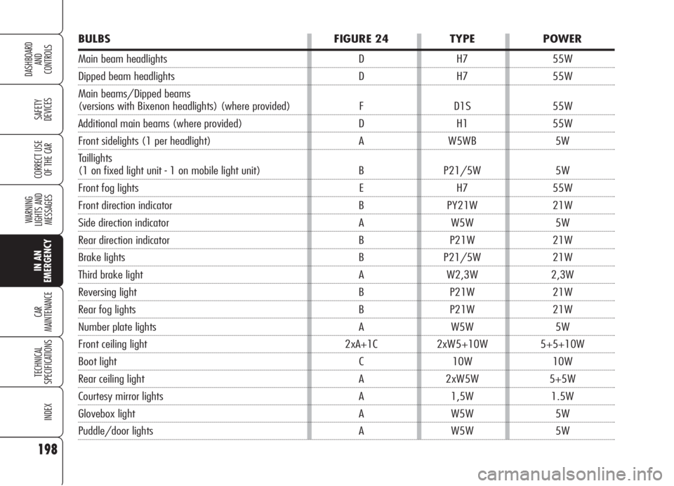
BULBS FIGURE 24 TYPE POWER
Main beam headlights D H7 55W
Dipped beam headlights D H7 55W
Main beams/Dipped beams
(versions with Bixenon headlights) (where provided) F D1S 55W
Additional main beams (where provided) D H1 55W
Front sidelights (1 per headlight) A W5WB 5W
Taillights
(1 on fixed light unit - 1 on mobile light unit) B P21/5W 5W
Front fog lights E H7 55W
Front direction indicator B PY21W 21W
Side direction indicator A W5W 5W
Rear direction indicator B P21W 21W
Brake lights B P21/5W 21W
Third brake light A W2,3W 2,3W
Reversing light B P21W 21W
Rear fog lights B P21W 21W
Number plate lights A W5W 5W
Front ceiling light 2xA+1C 2xW5+10W 5+5+10W
Boot light C 10W 10W
Rear ceiling light A 2xW5W 5+5W
Courtesy mirror lights A 1,5W 1.5W
Glovebox light A W5W 5W
Puddle/door lights A W5W 5W
Page 210 of 299

208
SAFETY
DEVICES
WARNING
LIGHTS AND
MESSAGES
CAR
MAINTENANCE
TECHNICAL
SPECIFICATIONS
INDEX
CORRECT USE
OF THE CAR
DASHBOARD
AND
CONTROLS
IN AN
EMERGENCY
BOOT LIGHT
To change the bulb, proceed as follows:
❒open the tailgate;
❒remove the light unit A-fig. 50lev-
ering in the point shown by the ar-
row;
❒open the protection cover B-fig. 51
and replace the bulb releasing it from
the side contacts making sure that
the new bulb is correctly clamped be-
tween the contacts;
❒re-close the protective cover B;
❒refit the light unit inserting first one
side and then the other one until
hearing the locking click.
❒close protection B-fig. 53on light
unitA-fig. 52;
❒refit the light unit inserting first one
side and then the other one until
hearing the locking click.
A0E0205mfig. 50A0E0075mfig. 52A0E0204mfig. 51
PUDDLE LIGHT
To change the bulb, proceed as follows:
❒open the door and remove lens A-
fig. 52levering in the point shown
by the arrow;
❒raise protectionB-fig. 53and re-
place the snap-fitted bulb;
A0E0235mfig. 53