brake Alfa Romeo 159 2006 Owner handbook (in English)
[x] Cancel search | Manufacturer: ALFA ROMEO, Model Year: 2006, Model line: 159, Model: Alfa Romeo 159 2006Pages: 299, PDF Size: 4.64 MB
Page 154 of 299

152
SAFETY
DEVICES
WARNING
LIGHTS AND
MESSAGES
IN AN
EMERGENCY
CAR
MAINTENANCE
TECHNICAL
SPECIFICATIONS
INDEX
DASHBOARD
AND
CONTROLS
CORRECT USE
OF THE CAR
STARTING PROCEDURE FOR
PETROL VERSIONS
Proceed as follows:
❒ Ensure that the handbrake is up;
❒Put the gear lever neutral;
❒Fit the electronic key into the ignition
device to stop limit;
❒Press the clutch (or brake) pedal down
to the floor without pressing the ac-
celerator;
❒Press button START/STOPand re-
lease it as soon as the engine starts.
We recommend that
during the initial period
you do not drive to full
car performance (e.g.: excessive
acceleration, long journeys at
top speed, sharp braking, etc.).
Running the engine in
confined areas is ex-
tremely dangerous. The engine
consumes oxygen and pro-
duces carbon monoxide which
is a highly toxic and lethal gas.
WARNING
When the engine is
switched off never leave
the electronic key into the
ignition device to prevent point-
less current absorption from
draining the batter.STARTING PROCEDURE FOR
DIESEL VERSIONS
Proceed as follows:
❒Ensure that the handbrake is up;
❒Put the gear lever neutral;
❒fit the electronic key down into the
ignition device until it stops. The in-
strument panel warning light
m
will turn on;
❒Wait for the warning light mto
turn off. The hotter the engine is, the
quicker this will happen;
❒Press the clutch (or brake) pedal
down to the floor without pressing the
accelerator;
❒Press button START/STOPas soon
as warning light
mgoes out. If you
wait too long you will lose the ben-
efit of the work done by the glow
plugs. Release the button as soon as
the engine starts.
ENGINE STARTING
The car is fitted with an electronic engine
immobilising system. If the engine fails
to start, see paragraph “Alfa Romeo
CODE system” in section “Dashboard
and controls”.
IMPORTANTTampering with the ig-
nition device can cause unrequired steer-
ing lock.
IMPORTANT Fit completely the elec-
tronic key into the ignition device until
it locks into place.
IMPORTANT Never take the elec-
tronic key out of the ignition device while
the car is moving unless you have to car-
ry out an emergency removal (see para-
graph “Removing the electronic key from
the ignition device in an emergency”),
this ensures that the steering column lock
is deactivated while the car is moving
(e.g.: towing the car).
Page 155 of 299

153
SAFETY
DEVICES
WARNING
LIGHTS AND
MESSAGES
IN AN
EMERGENCY
CAR
MAINTENANCE
TECHNICAL
SPECIFICATIONS
INDEX
DASHBOARD
AND
CONTROLS
CORRECT USE
OF THE CAR
IMPORTANT
If at start-up the engine turns off, restart
it by pressing the clutch or brake pedal
and then press button START/STOP.
If after a few attempts the engine does
not start, do not insist but contact Alfa
Romeo Authorized Services.
With car started the electronic key is
locked into the ignition device and it can
be removed only after switching the en-
gine off. With car running and key
locked into the ignition device, forced
key removal could damage the ignition
device.
Start-up failures, if any, are indicated by
the turning on of the warning light
Y
on the instrument panel (on certain ver-
sions a dedicated message is displayed).
In this case contact Alfa Romeo Autho-
rized Services.
If the engine will not start after pressing
buttonSTART/STOP, repeat the
start-up procedure by pressing the oth-
er pedal (clutch or brake). Start-up failures
The system can recognise start-up fail-
ures.
In the event of failure, the electronic key
can be removed from the ignition device to
enable the driver to carry out the follow-
ing operations:
❒turn the instrument panel off by
pressing button START/STOPor
removing the electronic key from the
ignition device;
❒start the engine again by pressing the
clutch/brake pedal and button
START/STOP.
IMPORTANT In the event of engine
locking while the car is running, due to
safety reasons it will not be possible to
take the electronic key out of the igni-
tion device. To remove it, press button
START/STOPwith brake pedal (or
clutch pedal) released and car stopped.
HOW TO WARM UP THE
ENGINE AFTER IT HAS
JUST STARTED
(petrol and diesel engines)
Proceed as follows:
❒Drive off slowly, letting the engine
turn at medium revs. Do not acceler-
ate abruptly;
❒Do not drive at full performance for
the initial kilometres. Wait until the
coolant temperature gauge starts
moving.
Page 156 of 299

154
SAFETY
DEVICES
WARNING
LIGHTS AND
MESSAGES
IN AN
EMERGENCY
CAR
MAINTENANCE
TECHNICAL
SPECIFICATIONS
INDEX
DASHBOARD
AND
CONTROLS
CORRECT USE
OF THE CAR
IMPORTANTAfter a taxing drive, you
should allow the engine to “catch its
breath” before turning it off by letting it
idle to allow the temperature in the en-
gine compartment to fall.
IMPORTANTTurning the car off will
deactivate the electronic safety systems
and turn off the external lights.IMPORTANTIn the event of engine
locking while the car is running, due to
safety reasons it will not be possible to
take the electronic key out of the igni-
tion device. To remove it, turn the in-
strument panel on and off by pressing
buttonSTART/STOPwith brake ped-
al (and clutch pedal) released and car
stopped.
REMOVING THE ELECTRONIC
KEY FROM THE IGNITION
DEVICE IN AN EMERGENCY
In the event of a failure at engine switch-
ing off system or at electronic key un-
locking system proceed as follows:
❒press the unlocking button to remove
the metal insert (see paragraph
“Electronic key” in section “Dash-
board and controls”);
STOPPING THE ENGINE
With car stopped press button START/
STOP. When the engine is off it will be
possible to remove the electronic key
from the ignition device.
A quick burst on the ac-
celerator before turning
off the engine serves
absolutely no practical purpose,
it wastes fuel and is damaging
especially to turbocharged en-
gines.❒fit the metal insert B-fig. 1of the
electronic key into the slot A;
❒remove the electronic key from the
ignition device.
IMPORTANTOnly fit the metal insert
Bof the electronic key into slot A-fig.1.
IMPORTANTStop the car before
emergency removal of the key, since re-
moving the key with the engine running
will turn both the engine and the in-
strument panel off and the steering lock
will not be engaged.
A0E0043mfig. 1In an emergency, and
for safety reasons the
engine can be turned off when
the car is running by pressing
repeatedly (3 times within
2 seconds) or by keeping
pressed button START/STOP
for a few seconds. In this case
the steering lock cannot be en-
gaged.
WARNING
Page 157 of 299

155
SAFETY
DEVICES
WARNING
LIGHTS AND
MESSAGES
IN AN
EMERGENCY
CAR
MAINTENANCE
TECHNICAL
SPECIFICATIONS
INDEX
DASHBOARD
AND
CONTROLS
CORRECT USE
OF THE CAR
To release the handbrake proceed as fol-
lows:
❒Slightly lift the handbrake Aand
press release button B;
❒Keep button Bpressed and lower the
lever. Warning light
xon the in-
strument panel will turn off.
Press the brake pedal when carrying out
this operation to prevent the car from
moving accidentally.
HANDBRAKE
The handbrake lever A-fig. 2 is locat-
ed between the two front seats. Pull the
handbrake lever Aupwards, until the
car cannot be moved.
With electronic key fitted into the igni-
tion device, the instrument panel warn-
ing light
xwill come on.
IMPORTANT The car shall stop after
a few clicks of the handbrake lever. If
this is not the case, contact Alfa Romeo
Authorized Services to have the hand-
brake adjusted.
A0E0030mfig. 2
PARKING THE CAR
Proceed as follows:
❒Stop the engine and engage the
handbrake;
❒Engage a gear (on a slope, engage
first gear if the car is faced uphill or
reverse if it is faced downhill) and
leave the wheels steered.
Block the wheels with a wedge or a stone
if the car is parked on a steep slope. Do
not leave the electronic key in the igni-
tion switch to prevent draining the bat-
tery.
Never leave children un-
attended in the car. Al-
ways remove the electronic key
when leaving the car and take
it out with you.
WARNING
Page 161 of 299

159
SAFETY
DEVICES
WARNING
LIGHTS AND
MESSAGES
IN AN
EMERGENCY
CAR
MAINTENANCE
TECHNICAL
SPECIFICATIONS
INDEX
DASHBOARD
AND
CONTROLS
CORRECT USE
OF THE CAR
Engage a low gear when driving down-
hill, rather than constantly using the
brake.
The weight the trailer exerts on the car
tow hook reduces by the same amount
the actual car loading capacity. To make
sure the maximum towable weight is
not exceeded (given in the log book)
account should be taken of the fully
laden trailer, including accessories and
personal belongings.
Do not exceed the speed limits of the
country you are driving in. In any case
do not exceed 100 km/h.TOWING TRAILERS
IMPORTANT NOTES
For towing caravans or trailers the car
must be fitted with a certified tow hook
and an adequate electric system. In-
stallation should be carried out by spe-
cialised personnel who release a special
document for circulation on the road.
Install any specific and/or additional
rear-view mirrors as specified by law.
Remember that when towing a trailer,
steep hills are harder to climb, the brak-
ing spaces increase and overtaking takes
longer depending on the overall weight.
The ABS system with
which the car may be
fitted does not control the
trailer braking system. Drive
with extreme care on slippery
roadbeds.
WARNING
Under no circumstances
should the car brake
system be altered to control
the trailer brake. The trailer
braking system must be fully
independent of the car hy-
draulic system.
WARNING
Page 162 of 299

160
SAFETY
DEVICES
WARNING
LIGHTS AND
MESSAGES
IN AN
EMERGENCY
CAR
MAINTENANCE
TECHNICAL
SPECIFICATIONS
INDEX
DASHBOARD
AND
CONTROLS
CORRECT USE
OF THE CAR
For the electric connection a unified con-
nector should be used which is gener-
ally placed on a special bracket normally
fastened to the towing device.
For the electrical connection, 7 pin
12VDC connection is to be used (CU-
NA/UNI and ISO/DIN Standards). Fol-
low the instructions provided by the car
manufacturer and/or the tow hitch man-
ufacturer.
An electric brake or other device (elec-
tric winch, etc.), if required, should be
supplied directly by the battery through
a cable with a cross section of no less
than 2.5 mm
2. In addition to the elec-
trical branches, the car’s electric system
can only be connected to the supply ca-
ble for an electric brake and to the ca-
ble for an internal light, though not
above 15W.Assembly diagram fig. 4
The tow hook structure must be fas-
tened in the points shown by the sym-
bol
Øusing a total of 10 M10 screws.
Fastening points (1) shall be fitted with
spacers with 20x4 mm diameter.
Counterplate (2) shall have 5 mm min-
imum thickness.
IMPORTANTIt is compulsory to fas-
ten a label (plainly visible) of suitable
size and material with the following
wording:
MAX LOAD ON BALL 70 kg
After fitting, screw holes shall be sealed
to prevent exhaust gas inlet.
IMPORTANTThe hook should be fas-
tened to the body avoiding any type of
drilling and trimming of the bumper.
INSTALLING THE TOW HOOK
The towing device should be fastened
to the body by specialised personnel ac-
cording to any additional and/or inte-
grative information supplied by the Man-
ufacturer of the device.
The towing device must meet current
regulations with reference to 94/20/EC
Directive and subsequent amendments.
For any version the towing device used
must match the towable weight of the
car on which it is to be installed.
Page 166 of 299

164
SAFETY
DEVICES
WARNING
LIGHTS AND
MESSAGES
IN AN
EMERGENCY
CAR
MAINTENANCE
TECHNICAL
SPECIFICATIONS
INDEX
DASHBOARD
AND
CONTROLS
CORRECT USE
OF THE CAR
CAR INACTIVITY
If the car is to be left inactive for longer
than a month, the following precautions
should be noted:
❒ park the car in covered, dry and if
possible well-ventilated premises;
❒ engage a gear;
❒check that the handbrake is not en-
gaged;
❒disconnect battery negative terminal
and check the battery charge. This
check is to be repeated every three
months when the car is left inactive.
Recharge if the optical indicator
shows a dark colour without the cen-
tral green area (see paragraph “Bat-
tery” in “Car maintenance” section);
❒clean and protect the painted parts
using protective wax;
❒clean and protect the shiny metal
parts using special compounds read-
ily available;
❒sprinkle talcum powder on the rubber
windscreen and rear window wiper
blades and lift them off the glass;
❒slightly open the windows;
❒cover the car with a cloth or perfo-
rated plastic sheet. Do not use sheets
of non-perforated plastic as they do
not allow moisture on the car body
to evaporate;
❒inflate tyres to +0.5 bar above the
normal specified pressure and check
it at intervals;
❒if you don’t disconnect the battery
from the electric system, check its
charge every month and recharge it
if the optical indicator shows a dark
colour without the central green area;
❒do not drain the engine cooling sys-
tem.
IMPORTANTIf the car is fitted with
alarm system, switch off the alarm with
the remote control.
Page 167 of 299

165
SAFETY
DEVICES
IN AN
EMERGENCY
CAR
MAINTENANCE
TECHNICAL
SPECIFICATIONS
INDEX
CORRECT USE
OF THE CAR
DASHBOARD
AND
CONTROLS
WARNING
LIGHTS AND
MESSAGES
W W
A A
R R
N N
I I
N N
G G
L L
I I
G G
H H
T T
S S
A A
N N
D D
M M
E E
S S
S S
A A
G G
E E
S S
LOW BRAKE FLUID/HANDBRAKE ON ..................... 167
BRAKE PAD WEAR ............................................. 167
SEAT BELTS NOT FASTENED ................................. 167
AIR BAG FAILURE................................................ 168
FRONT AIR BAGS DEACTIVATED ............................ 168
ENGINE COOLANT
HIGH TEMPERATURE ........................................... 169
ENGINE OIL HIGH TEMPERATURE .......................... 170
LOW ENGINE OIL PRESSURE/
EXHAUST OIL..................................................... 170
LOW BATTERY CHARGE ....................................... 170
INCOMPLETE DOOR LOCKING ............................... 171
BONNET OPEN ................................................... 171
BOOT OPEN....................................................... 171
INJECTION SYSTEM FAILURE/
EOBD SYSTEM FAILURE....................................... 171
CAR PROTECTION SYSTEM FAILURE/
STEERING LOCK INHIBITION................................. 172
ALARM FAILURE/BREAK-IN ATTEMPT
ELECTRONIC KEY NOT RECOGNIZED ...................... 172
POSSIBLE PRESENCE OF ICE ON THE ROAD............ 173
PRE-HEATING GLOW PLUGS/
PRE-HEATING GLOW PLUG FAILURE ....................... 173
WATER IN DIESEL FUEL FILTER ............................. 174
INERTIAL FUEL CUT-OFF
SWITCHED ON .................................................. 174
ABS SYSTEM FAILURE......................................... 175
EBD SYSTEM FAILURE......................................... 175
VDC SYSTEM .................................................... 175HILL HOLDER FAILURE ........................................ 176
ASR SYSTEM (WHEEL ANTISKID SYSTEM) ............. 176
EXTERNAL LIGHTS FAILURE .................................. 176
BRAKE LIGHTS FAILURE ....................................... 177
REAR FOGLIGHTS ............................................... 177
FRONT FOG LIGHTS ............................................ 177
SIDE/TAILLIGHTS/FOLLOW ME HOME .................. 177
DIPPED BEAM HEADLIGHTS.................................. 177
MAIN BEAM HEADLIGHTS .................................... 177
LEFT-HAND DIRECTION INDICATOR ........................ 177
RIGHT-HAND DIRECTION INDICATOR ...................... 177
LIGHT SENSOR FAILURE........................................ 178
RAIN SENSOR FAILURE......................................... 178
PARKING SENSORS FAILURE ................................ 178
FUEL RESERVE – LIMITED CRUISING RANGE .......... 178
CRUISE CONTROL .............................................. 178
DIESEL PARTICULATE FILTER CLOGGED .................. 178
ANTIPINCH SYSTEM FAILURE ............................... 179
WINDSCREEN WASHER FLUID LOW LEVEL ............. 179
SPEED LIMIT EXCEEDED ..................................... 179
T.P.M.S. SYSTEM FAILURE ................................... 179
CHECK TYRE PRESSURE ...................................... 179
LOW INFLATION PRESSURE ................................. 180
TYRE PRESSURE UNSUITABLE FOR SPEED ............. 180
Page 169 of 299

167
SAFETY
DEVICES
IN AN
EMERGENCY
CAR
MAINTENANCE
TECHNICAL
SPECIFICATIONS
INDEX
CORRECT USE
OF THE CAR
DASHBOARD
AND
CONTROLS
WARNING
LIGHTS AND
MESSAGES
SEAT BELTS NOT
FASTENED (red)
The warning light turns on
glowing steadily when:
❒the driver's seat belt is not fastened
correctly;
❒the passenger's seat belt is not fas-
tened correctly, heavy objects are
placed on the passenger's seat;
❒unfastening the driver's or the pas-
senger's seat belt.
With car moving the warning light will
turn on flashing together with the buzzer
for a short time.
The warning light will then stay on glow-
ing steadily.
The buzzer can be muted temporarily by
the following procedure:
❒fasten the front seat belts;
❒fit the electronic key into the ignition de-
vice;
❒wait for over 20 seconds but less than
1 minute and then unfasten one of the
front seat belts.
BRAKE PAD WEAR
(amber)
The warning light (where pro-
vided) turn on (on certain versions to-
gether with the message on the display)
if the front brake pads are worn; in this
case have them changed as soon as pos-
sible.
IMPORTANTSince the car is fitted
with wear sensors for the front brake
pads, when changing them, check also
the rear brake pads.
d
ling, check that the handbrake
is not engaged. If the warning
light stays on with handbrake
disengaged, stop the car im-
mediately and contact Alfa
Romeo Authorized Services.
WARNINGLOW BRAKE
FLUID
(red)
HANDBRAKE ON
(red)
Fitting the key into the ignition device
the warning light turns on, but it should
go off after few seconds.
Low brake fluid level
The warning light turns on (on certain
versions a dedicated message is dis-
played) when the level of the brake flu-
id in the reservoir falls below the mini-
mum level, due to possible leak in the
circuit.
Handbrake on
The warning light turns on when the
handbrake is on.
x
Page 179 of 299

177
SAFETY
DEVICES
IN AN
EMERGENCY
CAR
MAINTENANCE
TECHNICAL
SPECIFICATIONS
INDEX
CORRECT USE
OF THE CAR
DASHBOARD
AND
CONTROLS
WARNING
LIGHTS AND
MESSAGES
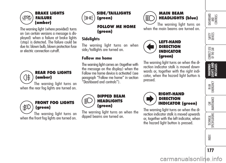
BRAKE LIGHTS
FAILURE
(amber)
The warning light (where provided) turns
on (on certain versions a message is dis-
played) when a failure at brake lights
(stop) is detected. The failure could be
due to: blown bulb, blown protection fuse
or electric connection cut-off.
T
REAR FOG LIGHTS
(amber)
The warning light turns on
when the rear fog lights are turned on.
FRONT FOG LIGHTS
(green)
The warning light turns on
when the front fog lights are turned on.
4
5
SIDE/TAILLIGHTS
(green)
FOLLOW ME HOME
(green)
Sidelights
The warning light turns on when
side/taillights are turned on.
Follow me home
The warning light comes on (together with
the message on the display) when the
Follow me home device is activated (see
paragraph “Follow me home” in section
“Dashboard and controls”).
3
2
DIPPED BEAM
HEADLIGHTS
(green)
The warning light turns on when the
dipped beams are turned on.
MAIN BEAM
HEADLIGHTS (blue)
The warning light turns on
when the main beams are turned on.
1
LEFT-HAND
DIRECTION
INDICATOR
(green)
The warning light turns on when the di-
rection indicator stalk is moved down-
wards or, together with the right indi-
cator, when the hazard light button is
pressed.
RIGHT-HAND
DIRECTION
INDICATOR (green)
The warning light turns on when the di-
rection indicator stalk is moved upwards
or, together with the left indicator, when
the hazard light button is pressed.
R
E