cooling system Alfa Romeo 159 2006 Owner handbook (in English)
[x] Cancel search | Manufacturer: ALFA ROMEO, Model Year: 2006, Model line: 159, Model: Alfa Romeo 159 2006Pages: 299, PDF Size: 4.64 MB
Page 59 of 299
57
SAFETY
DEVICES
WARNING
LIGHTS AND
MESSAGES
IN AN
EMERGENCY
CAR
MAINTENANCE
TECHNICAL
SPECIFICATIONS
INDEX
CORRECT USE
OF THE CAR
DASHBOARD
AND
CONTROLS
CLIMATE CONTROL
(fast cooling)
Proceed as follows:
❒turn knob Acompletely leftwards;
❒turn knob Cto top speed;
❒turn knob BtoO;
❒press buttons √andv(buttons
leds on).
How to keep the required
cooling
Proceed as follows:
❒turn air recirculation off (if on).
❒turn knob Ato the required temper-
ature;
❒turn the knurled ring Cto the required
fan speed.
LOOKING AFTER THE
SYSTEM
During the winter, the climate control
system
√must be turned on at least
once a month for about ten minutes.
Before summer, have the system
checked at Alfa Romeo Authorized Ser-
vices.
RECIRCULATION
To turn this function on press button
v: the button led will turn on.
This function is particularly useful when
the outside air is heavily polluted (in a
traffic jam, tunnel, etc.) However, it is
better not to use it for long periods, es-
pecially if there are several people in the
car to prevent window misting up.
Do not use the air recirculation function
on rainy/cold days as it would consid-
erably increase the possibility of the win-
dows misting inside.
IMPORTANTThe inside air recircula-
tion system makes it possible to reach
the required (“heating” or “cooling”)
conditions faster.After connecting/dis-
connecting the battery,
wait for 3 minutes at
least before fitting the electronic
key into the ignition device in
order to allow the climate con-
trol system control unit to reset
the positions of the electric ac-
tuators that adjust air temper-
ature and distribution.
Page 63 of 299
61
SAFETY
DEVICES
WARNING
LIGHTS AND
MESSAGES
IN AN
EMERGENCY
CAR
MAINTENANCE
TECHNICAL
SPECIFICATIONS
INDEX
CORRECT USE
OF THE CAR
DASHBOARD
AND
CONTROLS
AIR TEMPERATURE
ADJUSTMENT KNOBS
Turning the knob knurled rings (B/
E/P), clockwise or counter-clockwise,
respectively raises or lowers the tem-
perature of the air required respective-
ly in the left front zone (knob B) or right
front zone (knob E) or rear zone (knob
P) of the passenger compartment. The
temperatures set are shown on the dis-
playD/S.
Turning the knob knurled rings fully
clockwise or counter-clockwise until they
reach the extreme selections HIorLO,
the maximum heating or cooling func-
tions are respectively engaged.HI function (HIGH)
(maximum heating power)
It is switched on by setting a tempera-
ture of more than 32°C on the display,
and can be switched on independently
from the driver’s or passengers’ side, or
both of them; this setting brings the sys-
tem to the “one-zone” mode and it is
shown by both displays.
This functions can be switched on when
you wish to heat the passenger com-
partment as quickly as possible, by tak-
ing the greatest advantage from the sys-
tem potential.
The function uses the maximum tem-
perature of the heating fluid, whereas
air distribution and fan speed are con-
trolled automatically by the system.
SWITCHING THE CLIMATE
CONTROL SYSTEM ON
The system can be turned on by press-
ing any button (excluding
(,vand
MONO); it is however advisable to set
the required temperatures on the display
and then to press the AUTO button.
The climate control system allows to per-
sonalise required temperatures (driver and
passengers).
Page 64 of 299
62
SAFETY
DEVICES
WARNING
LIGHTS AND
MESSAGES
IN AN
EMERGENCY
CAR
MAINTENANCE
TECHNICAL
SPECIFICATIONS
INDEX
CORRECT USE
OF THE CAR
DASHBOARD
AND
CONTROLS
LO (LOW) function
(highest cooling power)
It is switched on by setting a tempera-
ture lower than 16°C on the display;
this setting is shown on the display. This
function can be switched on when you
wish to cool the passenger compartment
as quickly as possible, by taking the
greatest advantage from the system po-
tential.
The function cuts off air heating, switch-
es on both internal air recirculation (to
prevent hot air from entering the com-
partment) and the climate control com-
pressor, brings air distribution to
¯/˙
and the fan speed is controlled auto-
matically by the system. With the function switched on, howev-
er, all the manual settings can be made.
To switch the function off, you only need
to turn the ring of knob B/E/Pof the
temperature set to a value higher than
16°C; the opposite display and the rear
display (where provided) will show
16°C.
Pressing button AUTO, the display will
show a temperature of 16°C and re-
turns to an operating condition with au-
tomatic temperature adjustment. This function should not be ac-
tivated when the engine is cold,
to prevent air not warm enough
from entering the passenger
compartment.
With the function switched on, howev-
er, all the manual settings can be made.
To switch the function off, you only need
to turn the ring of knob (BorE/P) of
the temperature set to a value lower
than 32°C; the opposite display and the
rear display (where provided) will show
32°C.
Pressing button AUTO, the display will
show a temperature of 32°C and re-
turns to an operating condition with au-
tomatic temperature adjustment.
Page 68 of 299
66
SAFETY
DEVICES
WARNING
LIGHTS AND
MESSAGES
IN AN
EMERGENCY
CAR
MAINTENANCE
TECHNICAL
SPECIFICATIONS
INDEX
CORRECT USE
OF THE CAR
DASHBOARD
AND
CONTROLS
AIR DISTRIBUTION
SELECTION
Front seat Two-zone/
Three-zone configuration
Pressing buttons (front controls)
N/O/˙you can manually choose
one of the 7 possible modes for air dis-
tribution inside the compartment:
˙Flow of air to the dashboard centre
and side outlets (passenger’s body).
O˙Splitting of the air flow between
the vents to the lower part of the
passenger compartment (warmest
air) and the dashboard centre and
side outlets and the rear outlet
(coolest air).
OAir flow towards the front and rear
lower part of the passenger com-
partment. This type of distribution al-
lows heating of the passenger com-
partment in the shortest time by
proper setting of the temperature.
NSplitting of the air flow between
Owindscreen and front side window
demisting/defrosting vents and the
lower part of the passenger com-
partment. This type of air distribu-
tion allows satisfactory heating of
the passenger compartment while
preventing possible misting of the
windows.
NAir flow to the windscreen and front
side window vents to demist or de-
frost them.
N˙Splitting of the air flow between
the central/side dashboard vents,
rear vents and windscreen and
side window defrosting/demisting
vents. This type of air distribution
allows satisfactory ventilation of
the passenger compartment while
preventing possible misting of the
windows. With compressor off, the system will
check whether outside temperature is
higher or lower/same as the set one:
❒if outside temperature is lower than
the set one, the system will operate
regularly also with compressor off;
❒if outside temperature is higher than
the set one, the system will not be
able to keep the required condition,
the set temperature values will then
start to flash on the display.
Temperature detection (compressor off
and outside temperature higher than set
temperature) is activated each time the
electronic key is fitted into the ignition
device.
Operation of the cli-
mate control compres-
sor is necessary for cooling
and dehumidifying the air; it is
advisable to keep this function
always on, to prevent window
misting problems.
WARNING
Page 69 of 299
67
SAFETY
DEVICES
WARNING
LIGHTS AND
MESSAGES
IN AN
EMERGENCY
CAR
MAINTENANCE
TECHNICAL
SPECIFICATIONS
INDEX
CORRECT USE
OF THE CAR
DASHBOARD
AND
CONTROLS
N˙Splitting of the air flow between
Oall vents.
Rear seat Three-zone
configuration controls
Pressing buttons
N/O(rear controls)
you can manually choose one of the 3
possible modes for air distribution to the
rear side of passenger's compartment
NAir flow to the vents on the central
console (passengers’ body).
OAir flow towards the rear lower part
of the passenger compartment. This
type of distribution allows heating of the
passenger compartment in the shortest
time by proper setting of the tempera-
ture.
NSplitting of the air flow between
Othe vents to the lower part of the
passenger compartment (warmest air)
and the rear vents (coolest air).
To restore automatic air distribution con-
trol after a manual selection, press but-
tons AUTO (front controls) or AUTO (rear
controls).
AIR RECIRCULATION AND
AQS FUNCTION (AIR
QUALITY SYSTEM)
ON/OFF (where provided)
Inside air recirculation is controlled ac-
cording to the following operating log-
ics:
❒automatic control, indicated by but-
ton led “A”;
❒forced switching on (inside air recir-
culation always on), indicated by the
turning on of the circular led around
the button;
❒forced switching off (air recirculation
always off with air inlet from the out-
side), indicated by the turning off of
the circular led around the button.
With A.Q.S. (air quality sensor - where
provided), the operating logics becomes
sequential by pressing button
v.IMPORTANTThe inside air recircula-
tion system makes it possible to reach
the required heating or cooling condi-
tions faster. It is however inadvisable to
use it on rainy/cold days as it would
considerably increase the possibility of
the windows misting inside, especially
if the climate control compressor is off.
It is advisable to turn on the inside air
recirculation system in queues or tunnels
to avoid admitting polluted air from out-
side. The prolonged use of this function
should however be avoided, especially
with several persons on board, to avoid
the possibility of the windows misting
inside and to guarantee the required
fresh air inlet.
Page 166 of 299
164
SAFETY
DEVICES
WARNING
LIGHTS AND
MESSAGES
IN AN
EMERGENCY
CAR
MAINTENANCE
TECHNICAL
SPECIFICATIONS
INDEX
DASHBOARD
AND
CONTROLS
CORRECT USE
OF THE CAR
CAR INACTIVITY
If the car is to be left inactive for longer
than a month, the following precautions
should be noted:
❒ park the car in covered, dry and if
possible well-ventilated premises;
❒ engage a gear;
❒check that the handbrake is not en-
gaged;
❒disconnect battery negative terminal
and check the battery charge. This
check is to be repeated every three
months when the car is left inactive.
Recharge if the optical indicator
shows a dark colour without the cen-
tral green area (see paragraph “Bat-
tery” in “Car maintenance” section);
❒clean and protect the painted parts
using protective wax;
❒clean and protect the shiny metal
parts using special compounds read-
ily available;
❒sprinkle talcum powder on the rubber
windscreen and rear window wiper
blades and lift them off the glass;
❒slightly open the windows;
❒cover the car with a cloth or perfo-
rated plastic sheet. Do not use sheets
of non-perforated plastic as they do
not allow moisture on the car body
to evaporate;
❒inflate tyres to +0.5 bar above the
normal specified pressure and check
it at intervals;
❒if you don’t disconnect the battery
from the electric system, check its
charge every month and recharge it
if the optical indicator shows a dark
colour without the central green area;
❒do not drain the engine cooling sys-
tem.
IMPORTANTIf the car is fitted with
alarm system, switch off the alarm with
the remote control.
Page 171 of 299
169
SAFETY
DEVICES
IN AN
EMERGENCY
CAR
MAINTENANCE
TECHNICAL
SPECIFICATIONS
INDEX
CORRECT USE
OF THE CAR
DASHBOARD
AND
CONTROLS
WARNING
LIGHTS AND
MESSAGES
–Car heavy duty(e.g.: towing trail-
er uphill or fully laden car): decrease
speed, if the warning light stays on, stop
the car. Wait for 2 or 3 minutes leaving
the engine on and slightly accelerated to
further activate the circulation of the
coolant fluid, then switch the engine off.
IMPORTANTUnder severe use of the
car, keep the engine on and slightly ac-
celerated for few minutes before switch-
ing it off.
Warning light Findi-
cates also warning light
¬failures. This is indicated by
intermittent flashing, over 4
seconds, of warning light
F. In
this event warning light
¬could
not indicate safety system fail-
ures. Contact Alfa Romeo Au-
thorized Services to have the
system checked immediately.
WARNINGENGINE COOLANT
HIGH TEMPERATURE
(red)
Fitting the key into the ignition device,
the warning light (set on engine coolant
gauge) turns on but it shall go off after
a few seconds.
The warning light turns on (on certain
versions a dedicated message is dis-
played) to indicate engine overheating.
If the warning light comes on, proceed
as follows:
–Normal driving conditions: stop
the car, switch off the engine and check
whether the water level in the reservoir
is not below the MINmarl. Otherwise
wait for few seconds to allow engine
cooling, then open slowly and carefully
the cap, top up coolant and check
whether its level is falling between MIN
andMAXmarks in the reservoir. Check
visually any leak. If when restarting the
warning light comes on again, contact
Alfa Romeo Authorized Services .
u
With engine hot, do not
remove the cap: risk of
burnt.
WARNING
Page 234 of 299
232
SAFETY
DEVICES
WARNING
LIGHTS AND
MESSAGES
IN AN
EMERGENCY
TECHNICAL
SPECIFICATIONS
INDEX
CORRECT USE
OF THE CAR
DASHBOARD
AND
CONTROLS
CAR
MAINTENANCE
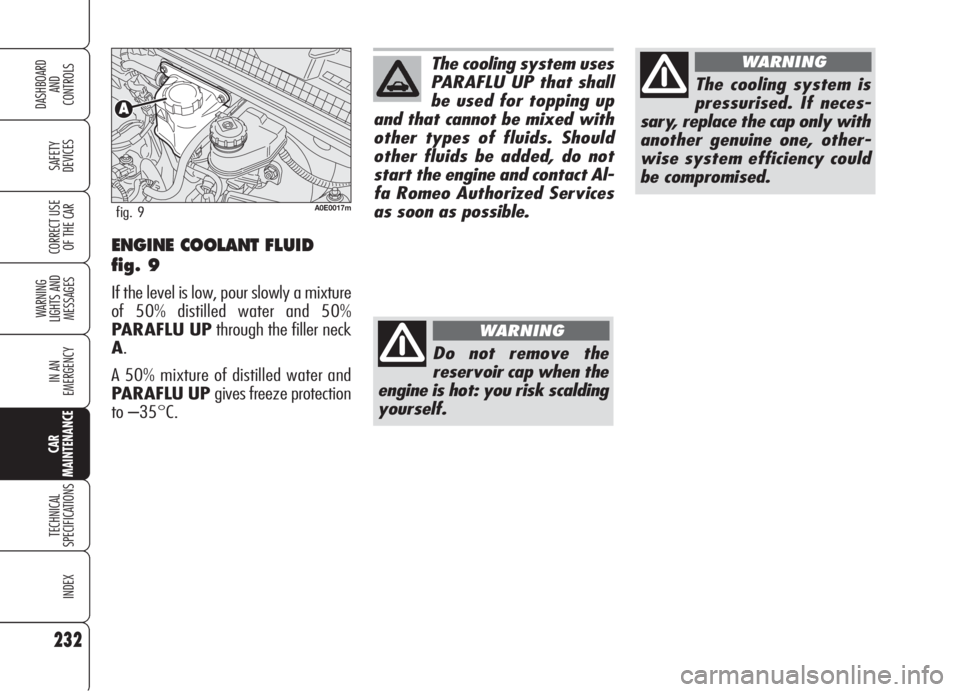
ENGINE COOLANT FLUID
fig. 9
If the level is low, pour slowly a mixture
of 50% distilled water and 50%
PARAFLU UPthrough the filler neck
A.
A 50% mixture of distilled water and
PARAFLU UP gives freeze protection
to –35°C.
A0E0017mfig. 9
The cooling system uses
PARAFLU UP that shall
be used for topping up
and that cannot be mixed with
other types of fluids. Should
other fluids be added, do not
start the engine and contact Al-
fa Romeo Authorized Services
as soon as possible.
Do not remove the
reservoir cap when the
engine is hot: you risk scalding
yourself.
WARNING
The cooling system is
pressurised. If neces-
sary, replace the cap only with
another genuine one, other-
wise system efficiency could
be compromised.
WARNING
Page 268 of 299
266
SAFETY
DEVICES
WARNING
LIGHTS AND
MESSAGES
IN AN
EMERGENCY
CAR
MAINTENANCE
INDEX
CORRECT USE
OF THE CAR
DASHBOARD
AND
CONTROLS
TECHNICALSPECIFICATIONS
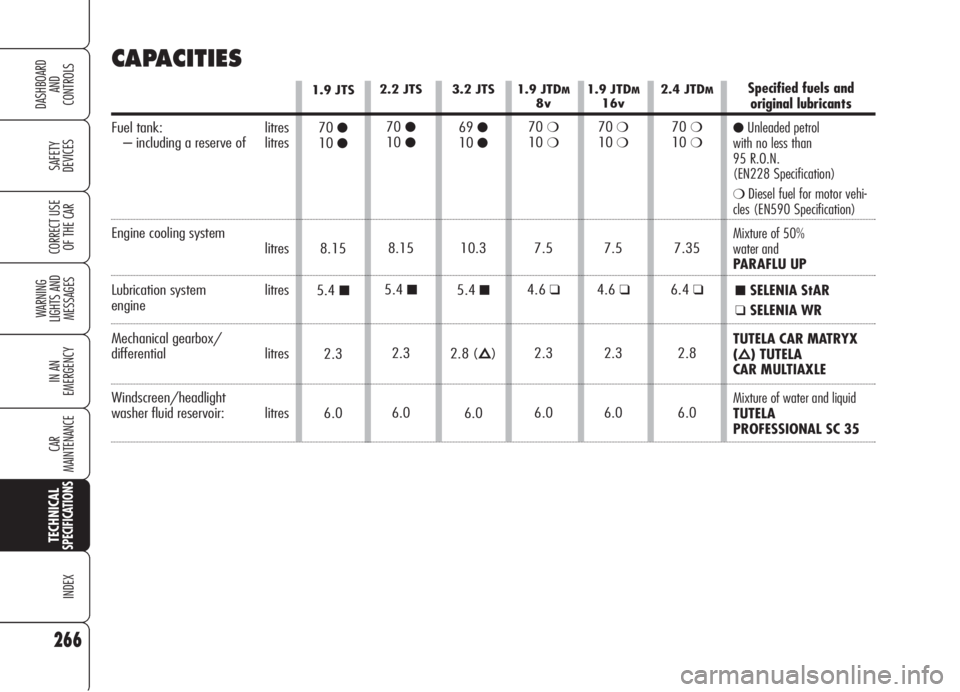
CAPACITIES
1.9 JTDM8v
70❍10❍
7.5
4.6
❑
2.3
6.0
1.9 JTDM16v
70❍10❍
7.5
4.6
❑
2.3
6.0
2.4 JTDM
70❍10❍
7.35
6.4
❑
2.8
6.0
1.9 JTS
70●10●
8.15
5.4
■
2.3
6.0
2.2 JTS
70●10●
8.15
5.4
■
2.3
6.0
3.2 JTS
69●10●
10.3
5.4
■
2.8 (Õ)
6.0
Specified fuels and
original lubricants
●Unleaded petrol
with no less than
95 R.O.N.
(EN228 Specification)
❍Diesel fuel for motor vehi-
cles (EN590 Specification)
Mixture of 50%
water and
PARAFLU UP
■SELENIA StAR
❑SELENIA WR
TUTELA CAR MATRYX
(Õ) TUTELA
CAR MULTIAXLE
Mixture of water and liquid
TUTELA
PROFESSIONAL SC 35
Fuel tank: litres
– including a reserve of litres
Engine cooling systemlitres
Lubrication system litres
engine
Mechanical gearbox/
differential litres
Windscreen/headlight
washer fluid reservoir: litres