oil Alfa Romeo 159 2006 Owner handbook (in English)
[x] Cancel search | Manufacturer: ALFA ROMEO, Model Year: 2006, Model line: 159, Model: Alfa Romeo 159 2006Pages: 299, PDF Size: 4.64 MB
Page 9 of 299
7
SAFETY
DEVICES
WARNING LIGHTS
AND MESSAGES
IN AN
EMERGENCY
CAR
MAINTENANCE
TECHNICAL
SPECIFICATIONS
INDEX
DASHBOARD
AND
CONTROLS
CORRECT USE
OF THE CAR
DASHBOARD
A0E0056mfig. 1
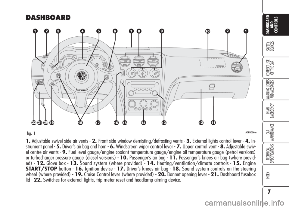
1.Adjustable swivel side air vents - 2.Front side window demisting/defrosting vents - 3.External lights control lever - 4.In-
strument panel - 5.Driver’s air bag and horn -6.Windscreen wiper control lever - 7.Upper central vent - 8.Adjustable swiv-
el centre air vents - 9.Fuel level gauge/engine coolant temperature gauge/engine oil temperature gauge (petrol versions)
or turbocharger pressure gauge (diesel versions) - 10.Passenger’s air bag - 11.Passenger’s knees air bag (where provid-
ed) - 12.Glove box - 13.Sound system (where provided) - 14.Heating/ventilation/climate controls - 15.Engine
START/STOPbutton - 16.Ignition device - 17.Driver’s knees air bag - 18.Sound system controls on the steering
wheel (where provided) - 19.Cruise Control lever (where provided) - 20.Bonnet opening lever - 21.Dashboard fusebox
lid - 22.Switches for external lights, trip meter reset and headlamp aiming device.
Page 25 of 299
23
SAFETY
DEVICES
WARNING LIGHTS
AND MESSAGES
IN AN
EMERGENCY
CAR
MAINTENANCE
TECHNICAL
SPECIFICATIONS
INDEX
DASHBOARD
AND
CONTROLS
CORRECT USE
OF THE CARIMPORTANTThe pointer can reach
the red area also for a sum of un-
favourable conditions, i.e.: slow speed,
uphill, fully laden or towing a trailer with
hot outside temperature.
TURBOCHARGER PRESSURE
GAUGE (diesel versions)
fig. 19
This shows the turbocharger pressure
value.
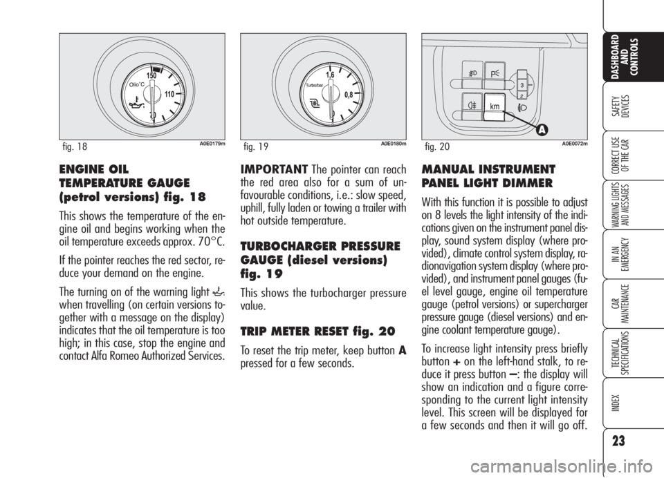
TRIP METER RESET fig. 20
To reset the trip meter, keep button A
pressed for a few seconds.
MANUAL INSTRUMENT
PANEL LIGHT DIMMER
With this function it is possible to adjust
on 8 levels the light intensity of the indi-
cations given on the instrument panel dis-
play, sound system display (where pro-
vided), climate control system display, ra-
dionavigation system display (where pro-
vided), and instrument panel gauges (fu-
el level gauge, engine oil temperature
gauge (petrol versions) or supercharger
pressure gauge (diesel versions) and en-
gine coolant temperature gauge).
To increase light intensity press briefly
button+on the left-hand stalk, to re-
duce it press button –: the display will
show an indication and a figure corre-
sponding to the current light intensity
level. This screen will be displayed for
a few seconds and then it will go off.
ENGINE OIL
TEMPERATURE GAUGE
(petrol versions) fig. 18
This shows the temperature of the en-
gine oil and begins working when the
oil temperature exceeds approx. 70°C.
If the pointer reaches the red sector, re-
duce your demand on the engine.
The turning on of the warning light
`
when travelling (on certain versions to-
gether with a message on the display)
indicates that the oil temperature is too
high; in this case, stop the engine and
contact Alfa Romeo Authorized Services.
A0E0179mfig. 18A0E0180mfig. 19A0E0072mfig. 20
Page 26 of 299
24
SAFETY
DEVICES
WARNING LIGHTS
AND MESSAGES
IN AN
EMERGENCY
CAR
MAINTENANCE
TECHNICAL
SPECIFICATIONS
INDEX
DASHBOARD
AND
CONTROLS
CORRECT USE
OF THE CAR
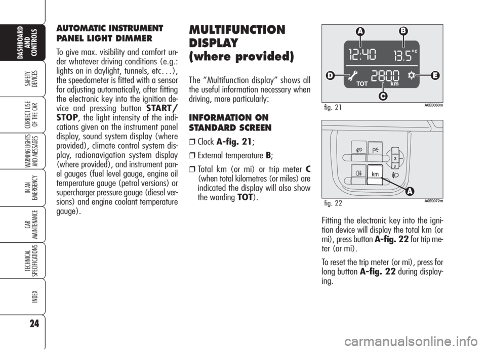
Fitting the electronic key into the igni-
tion device will display the total km (or
mi), press button A-fig. 22for trip me-
ter (or mi).
To reset the trip meter (or mi), press for
long button A-fig. 22during display-
ing.
MULTIFUNCTION
DISPLAY
(where provided)
The “Multifunction display” shows all
the useful information necessary when
driving, more particularly:
INFORMATION ON
STANDARD SCREEN
❒ClockA-fig. 21;
❒External temperature B;
❒Total km (or mi) or trip meter C
(when total kilometres (or miles) are
indicated the display will also show
the wording TOT).
A0E0060mfig. 21
A0E0072mfig. 22
AUTOMATIC INSTRUMENT
PANEL LIGHT DIMMER
To give max. visibility and comfort un-
der whatever driving conditions (e.g.:
lights on in daylight, tunnels, etc…),
the speedometer is fitted with a sensor
for adjusting automatically, after fitting
the electronic key into the ignition de-
vice and pressing button START/
STOP, the light intensity of the indi-
cations given on the instrument panel
display, sound system display (where
provided), climate control system dis-
play, radionavigation system display
(where provided), and instrument pan-
el gauges (fuel level gauge, engine oil
temperature gauge (petrol versions) or
supercharger pressure gauge (diesel ver-
sions) and engine coolant temperature
gauge).
Page 27 of 299
25
SAFETY
DEVICES
WARNING LIGHTS
AND MESSAGES
IN AN
EMERGENCY
CAR
MAINTENANCE
TECHNICAL
SPECIFICATIONS
INDEX
DASHBOARD
AND
CONTROLS
CORRECT USE
OF THE CAR
INFORMATION ABOUT CAR
CONDITIONS (at event)
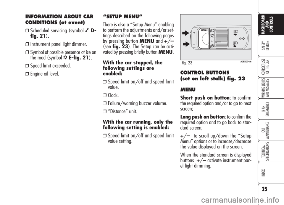
❒Scheduled servicing (symbol õD-
fig. 21).
❒Instrument panel light dimmer.
❒Symbol of possible presence of ice on
the road (symbol
√E-fig. 21).
❒Speed limit exceeded.
❒Engine oil level.
A0E0074mfig. 23
“SETUP MENU”
There is also a “Setup Menu” enabling
to perform the adjustments and/or set-
tings described on the following pages
by pressing button MENUand+/–
(seefig. 23). The Setup can be acti-
vated by pressing briefly button MENU.
With the car stopped, the
following settings are
enabled:
❒Speed limit on/off and speed limit
value.
❒Clock.
❒Failure/warning buzzer volume.
❒“Distance” unit.
With the car running, only the
following setting is enabled:
❒Speed limit on/off and speed limit
value setting.
CONTROL BUTTONS
(set on left stalk) fig. 23
MENU
Short push on button: to confirm
the required option and/or to go to next
screen;
Long push on button: to confirm the
required option and to go back to stan-
dard screen;
+/–to scroll up/down the “Setup
Menu” options or to increase/decrease
the value displayed on the screen.
When the standard screen is displayed
buttons+/–activate instrument pan-
el light dimming.
Page 30 of 299
ENGINE OIL LEVEL
INDICATION
Fitting the electronic key into the igni-
tion device, the display will show for a
few seconds the engine oil level. At this
stage, to clear this indication and to go
to next screen, press button MENU.
Low oil level will be indicated by a ded-
icated warning message on the display.
IMPORTANT Check the proper en-
gine oil level on the dipstick (see para-
graph “Checking levels” in section “Car
maintenance”).
IMPORTANTProper engine oil level
shall be checked with the car on level
ground.
IMPORTANT To read the correct oil
level after fitting the electronic key, wait
for about 2 seconds before starting the
engine.
IMPORTANT Engine oil level could in-
crease after a long stop.
MESSAGES DISPLAYED
AT STARTING
After the engine oil level, the display will
show for a few seconds a message in-
dicating the procedure to follow to start
the engine (PRESS PEDAL AND
START: press brake or clutch pedal and
then press button START/STOPto
start the engine). Scheduled servicing
IMPORTANTThe Service schedule in-
cludes car maintenance every 30,000
km (or 18,000 mi); this is shown au-
tomatically, with the electronic key in-
to the ignition device starting from
2,000 km (or 1,240 mi) from this
deadline and it will be displayed in km
or miles according to the unit set. When
a scheduled service interval (“coupon”)
is near to come, fitting the electronic key
into the ignition device will display a
message followed by the number of
km/mi to go before car servicing. Con-
tact Alfa Romeo Authorized Services to
carry out any service operation provid-
ed by the Service schedule or by the An-
nual inspection plan, and to reset the
display.
28
SAFETY
DEVICES
WARNING LIGHTS
AND MESSAGES
IN AN
EMERGENCY
CAR
MAINTENANCE
TECHNICAL
SPECIFICATIONS
INDEX
CORRECT USE
OF THE CAR
DASHBOARD
AND
CONTROLS
Page 32 of 299
30
SAFETY
DEVICES
WARNING LIGHTS
AND MESSAGES
IN AN
EMERGENCY
CAR
MAINTENANCE
TECHNICAL
SPECIFICATIONS
INDEX
DASHBOARD
AND
CONTROLS
CORRECT USE
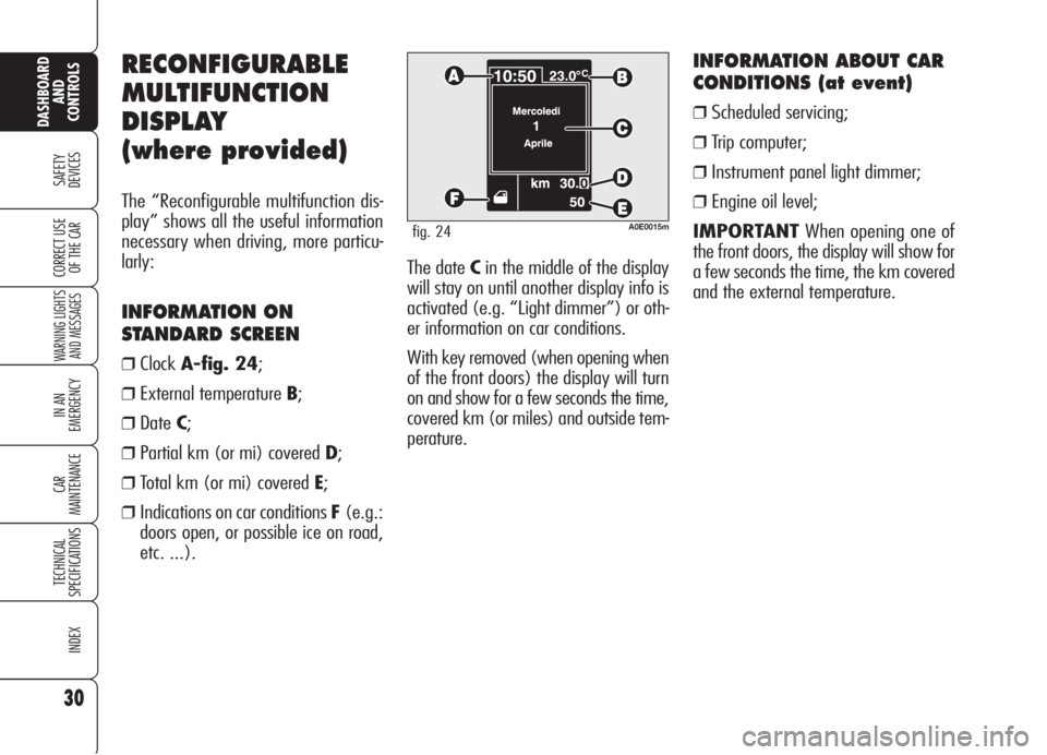
OF THE CARThe date Cin the middle of the display
will stay on until another display info is
activated (e.g. “Light dimmer”) or oth-
er information on car conditions.
With key removed (when opening when
of the front doors) the display will turn
on and show for a few seconds the time,
covered km (or miles) and outside tem-
perature.
INFORMATION ABOUT CAR
CONDITIONS (at event)
❒Scheduled servicing;
❒Trip computer;
❒Instrument panel light dimmer;
❒Engine oil level;
IMPORTANTWhen opening one of
the front doors, the display will show for
a few seconds the time, the km covered
and the external temperature.
RECONFIGURABLE
MULTIFUNCTION
DISPLAY
(where provided)
The “Reconfigurable multifunction dis-
play” shows all the useful information
necessary when driving, more particu-
larly:
INFORMATION ON
STANDARD SCREEN
❒ClockA-fig. 24;
❒External temperature B;
❒DateC;
❒Partial km (or mi) covered D;
❒Total km (or mi) covered E;
❒Indications on car conditions F(e.g.:
doors open, or possible ice on road,
etc. ...).
A0E0015mfig. 24
Page 34 of 299
32
SAFETY
DEVICES
WARNING LIGHTS
AND MESSAGES
IN AN
EMERGENCY
CAR
MAINTENANCE
TECHNICAL
SPECIFICATIONS
INDEX
DASHBOARD
AND
CONTROLS
CORRECT USE
OF THE CAR
Selecting “Date” and “Clock”:
❒briefly press button MENUto select
the first value to change (e.g. hours/
minutes or year/month/day);
❒operate buttons +or–(by single
press) to select the new setting;
❒briefly press button MENUto store
the new setting and to go to the next
setup menu option, if this is the last
one you will go back to the previously
selected option of the main menu.
ENGINE OIL LEVEL
INDICATION
Fitting the electronic key into the igni-
tion device, the display will show for a
few seconds the engine oil level. At this
stage, to clear this indication and to go
to next screen, press button MENU.
Low oil level will be indicated by a ded-
icated warning message on the display.
IMPORTANT Check the proper en-
gine oil level on the dipstick (see para-
graph “Checking levels” in section “Car
maintenance”).
IMPORTANTProper engine oil level
shall be checked with the car on level
ground.
IMPORTANT To read the correct oil
level after fitting the electronic key, wait
for about 2 seconds before starting the
engine.
IMPORTANT Engine oil level could in-
crease after a long stop. Selecting an option of the main
menu with submenu:❒briefly press button MENUto display
the first submenu option;
❒operate buttons +or–(by single
press) to scroll all submenu options;
❒briefly press button MENUto select
the displayed submenu option and to
enter the corresponding setup menu;
❒operate buttons +or–(by single
press) to select the new setting of this
submenu option;
❒briefly press button MENUto store
the new setting and go back to the
previously selected submenu option.
Page 54 of 299

52
SAFETY
DEVICES
WARNING
LIGHTS AND
MESSAGES
IN AN
EMERGENCY
CAR
MAINTENANCE
TECHNICAL
SPECIFICATIONS
INDEX
CORRECT USE
OF THE CAR
DASHBOARD
AND
CONTROLS
Storing the “parking”
position of the door mirror
on the passenger side
On versions equipped with electric seats,
when engaging reverse for parking to
improve visibility the driver can adjust
(and store) the passenger's door mirror
to a position different than that used
commonly. To store mirror position pro-
ceed as follows:
❒To perform storing, proceed as fol-
lows: engage reverse with car
stopped and electronic key fitted in-
to the ignition device;
❒move device A-fig. 39to position
2(passenger door mirror selection);
❒adjust the passenger door mirror to
obtain the best position for parking
manoeuvres;
❒keep one of the buttons C-fig. 33
pressed for at least 3 seconds (see
paragraph “Seats” in this section).
Together with the passenger door mir-
ror “parking” position, also the driver
seat position and the driver door mirror
will be stored. The sound of a buzzer
will confirm that the mirror position has
been stored.Recalling the passenger door
mirror “parking” position
Proceed as follows: fit the electronic key
into the ignition device, engage reverse,
move device A-fig. 39to position 2
(passenger door mirror selection).
The mirror will set automatically to the
previously stored position.
If no parking position has been stored,
when engaging reverse the passenger
door mirror will slightly lower to favour
the parking manoeuvre.
The passenger door mirror will return au-
tomatically to its original position about
10 seconds after disengaging reverse,
immediately after exceeding 10 km/h
with forward gear or when moving de-
viceA-fig. 39to0.Automatic door mirror
realignment
Each time the electronic key is fitted in-
to the ignition device the door mirrors
return automatically to the last position
reached and/or recalled before remov-
ing the electronic key from the ignition
device.
This enables mirror alignment if, when
the car is parked, one of the door mir-
rors has been moved manually and/or
accidentally.
Defrosting/demisting
The electric mirrors are fitted with heat-
ing coils which come into operation
when turning on the heated rear win-
dow (pressing button
().
IMPORTANTThis function is timed
and is deactivated after a few minutes.
Page 105 of 299
103
SAFETY
DEVICES
WARNING
LIGHTS AND
MESSAGES
IN AN
EMERGENCY
CAR
MAINTENANCE
TECHNICAL
SPECIFICATIONS
INDEX
CORRECT USE
OF THE CAR
DASHBOARD
AND
CONTROLS
TAILGATE CLOSING
Lower the tailgate pressing the lock un-
til hearing the locking click.
IMPORTANT If the option for ”Indep.
boot” is on, before closing the boot,
check whether you have with you the
ignition key since the boot will be locked
automatically.
The addition of objects
(speakers, spoilers, etc.)
on the rear shelf or boot
lid, except those envisaged by
the manufacturer, may prevent
the gas filled struts at the sides
of the boot from working prop-
erly.
When using the boot,
make sure the loads do
not exceed the permitted
weight (see “Technical specifi-
cations” chapter). Also make
sure the items in the boot are
arranged properly to prevent
them being thrown forwards
and injuring passengers should
you brake sharply.
WARNING
Never travel with ob-
jects on the rear shelf
to prevent them being thrown
forwards and injuring passen-
gers in case of accident or
sharp braking.
WARNING
EXTENDING THE BOOT
(where provided)
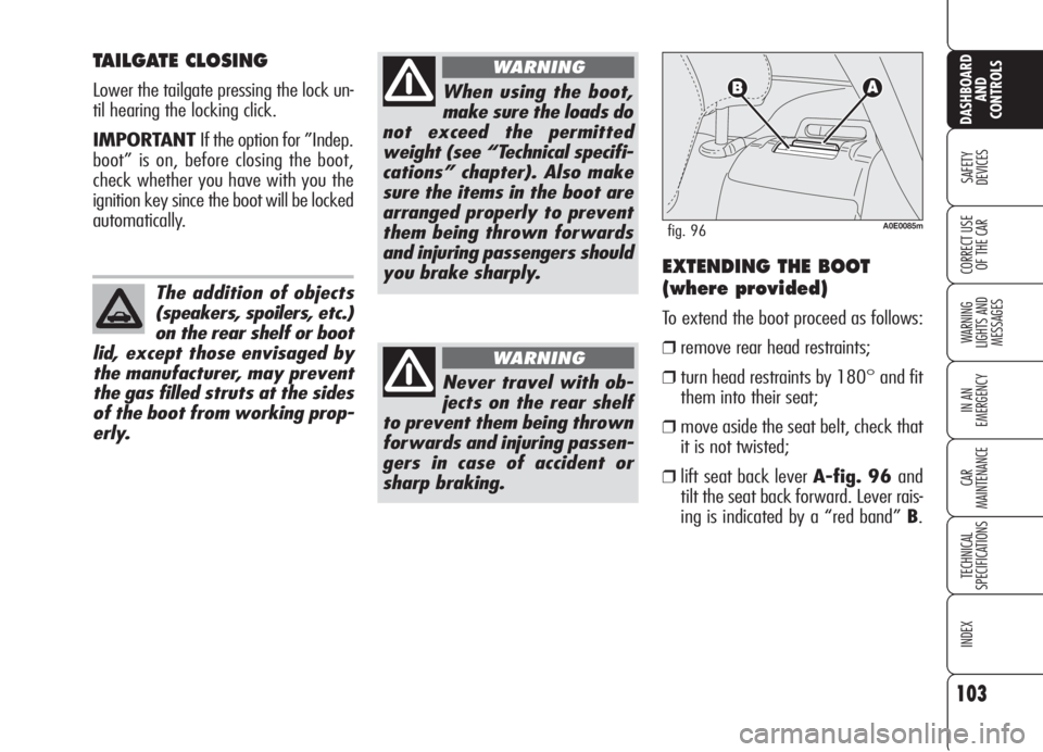
To extend the boot proceed as follows:
❒remove rear head restraints;
❒turn head restraints by 180° and fit
them into their seat;
❒move aside the seat belt, check that
it is not twisted;
❒lift seat back lever A-fig. 96 and
tilt the seat back forward. Lever rais-
ing is indicated by a “red band” B.
A0E0085mfig. 96
Page 119 of 299
117
SAFETY
DEVICES
WARNING
LIGHTS AND
MESSAGES
IN AN
EMERGENCY
CAR
MAINTENANCE
TECHNICAL
SPECIFICATIONS
INDEX
CORRECT USE
OF THE CAR
DASHBOARD
AND
CONTROLS
RADIO TRANSMITTERS AND
CELLULAR TELEPHONES
Radio transceiver equipment (e.g.: e-
tacs mobile phones, HAM radio systems
and the like) shall not be used inside the
car unless a separate aerial is mounted
outside the car.
The use of these devices inside the pas-
senger compartment (without external
aerial) may cause electrical systems
equipping the car to malfunction. This
could compromise car safety in addition
to constituting a potential hazard for the
passengers.
In addition, transmission and reception
of these devices may be affected by the
shielding effect of the car body.
As concerns the use of mobile phones
(GSM, GPRS, UMTS) provided with of-
ficial EC approval, strictly comply with
the instructions given by the mobile
phone manufacturer.
ACCESSORIES
PURCHASED
BY THE OWNER
If after buying the car, you decide to in-
stall electrical accessories that require a
permanent electric supply (alarm, satel-
lite antitheft system, etc.) or accessories
that in any case burden the electric sup-
ply, contact Alfa Romeo Authorized Ser-
vices, whose qualified personnel, besides
suggesting the most suitable devices be-
longing to Lineaccessori Alfa Romeo, will
also evaluate the overall electric absorp-
tion, checking whether the car’s electric
system is able to withstand the load re-
quired, or whether it needs to be inte-
grated with a more powerful battery.
Take care when fitting
additional spoilers, al-
loy rims and non-standard
wheel caps: they might reduce
ventilation of the brakes, thus
their efficiency, during abrupt
and repeated braking, or long
downhill slopes. Make sure
that nothing (mats, etc.) gets
in the way of the pedals when
they are pushed down.
WARNING