engine Alfa Romeo 159 2008 Owner handbook (in English)
[x] Cancel search | Manufacturer: ALFA ROMEO, Model Year: 2008, Model line: 159, Model: Alfa Romeo 159 2008Pages: 303, PDF Size: 5.18 MB
Page 83 of 303

81
SAFETY
DEVICES
WARNING
LIGHTS AND
MESSAGES
IN AN
EMERGENCY
CAR
MAINTENANCE
TECHNICAL
SPECIFICATIONS
INDEX
CORRECT USE
OF THE CAR
DASHBOARD
AND
CONTROLS
CONTROLS
POWER SUPPLY AND FUEL
CUT-OFF SWITCHES
The car is fitted with a safety switch that
in the event of a crash comes into op-
eration by cutting off fuel and turning
off the engine as a consequence.
Certain versions are equipped with an
additional safety switch that in the event
of a crash comes into operation by cut-
ting off the power supply.
These two safety switches therefore pre-
vent dangerous fuel leaks due to fuel
line cracking, and sparks or electric dis-
charges due to damaging or malfunc-
tioning of the electric components of the
car in the event of a crash.
IMPORTANTAfter a crash, remem-
ber to remove the key from the ignition
device to prevent battery run-down.
If, after a crash, you
smell fuel or see leaks
from the fuel system, do not
reset the switches to avoid
fire risk.
WARNING
If central door locking
has been activated
from inside the car and after a
crash the fuel cut-off switch
cannot activate automatic door
unlocking, it will not be pos-
sible to get into the car. In any
case, door opening from the
outside depends on door con-
ditions after the crash: if a
door is badly damaged it will
be impossible to open it. In this
event try to open one of the
other doors.
WARNING
Door unlocking in the event
of a crash
In the event of a crash that triggers the
fuel cut-off switch, the doors will unlock
automatically to enable getting into the
car and at the same time the passen-
ger’s compartment lights will turn on.
It is however always possible to open
the doors from the passenger’s com-
partment by means of the internal door
handles.
If, after a crash no fuel leaks or dam-
ages to the electric devices (e.g. head-
lights) are found and the car can be
started again, reset the fuel cut-off
switch and the power supply cut-off
switch (where provided). Follow the in-
structions given below.
Page 88 of 303
86
SAFETY
DEVICES
WARNING
LIGHTS AND
MESSAGES
IN AN
EMERGENCY
CAR
MAINTENANCE
TECHNICAL
SPECIFICATIONS
INDEX
CORRECT USE
OF THE CAR
DASHBOARD
AND
CONTROLS
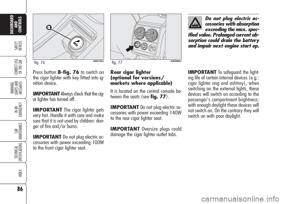
Press button B-fig. 76to switch on
the cigar lighter with key fitted into ig-
nition device.
IMPORTANTAlways check that the cig-
ar lighter has turned off.
IMPORTANTThe cigar lighter gets
very hot. Handle it with care and make
sure that it is not used by children: dan-
ger of fire and/or burns.
IMPORTANT Do not plug electric ac-
cessories with power exceeding 100W
to the front cigar lighter seat.
A0E0152mfig. 76
Rear cigar lighter
(optional for versions/
markets where applicable)
It is located on the central console be-
tween the seats (see fig. 77).
IMPORTANTDo not plug electric ac-
cessories with power exceeding 140W
to the rear cigar lighter seat.
IMPORTANTOversize plugs could
damage the cigar lighter outlet tabs.
Do not plug electric ac-
cessories with absorption
exceeding the max. spec-
ified value. Prolonged current ab-
sorption could drain the battery
and impair next engine start up.
OFF
O
I
AUTOAUTO
A0E0068mfig. 77
IMPORTANTTo safeguard the light-
ing life of certain internal devices (e.g.:
cigar lighter ring and ashtray), when
switching on the external lights, these
devices will switch on according to the
passenger's compartment brightness:
with enough daylight these devices will
not switch on. On the contrary they will
switch on with poor daylight.
Page 91 of 303
PROGRAMMING
IMPORTANTWhile programming the
system, check for the absence of peo-
ple, animals or objects within the ma-
noeuvre space of main doors or gates to
prevent the risk of injuries or damages.
IMPORTANTPull up the handbrake
and fit the key into the ignition device.
Do not start the engine.Proceed as follows:
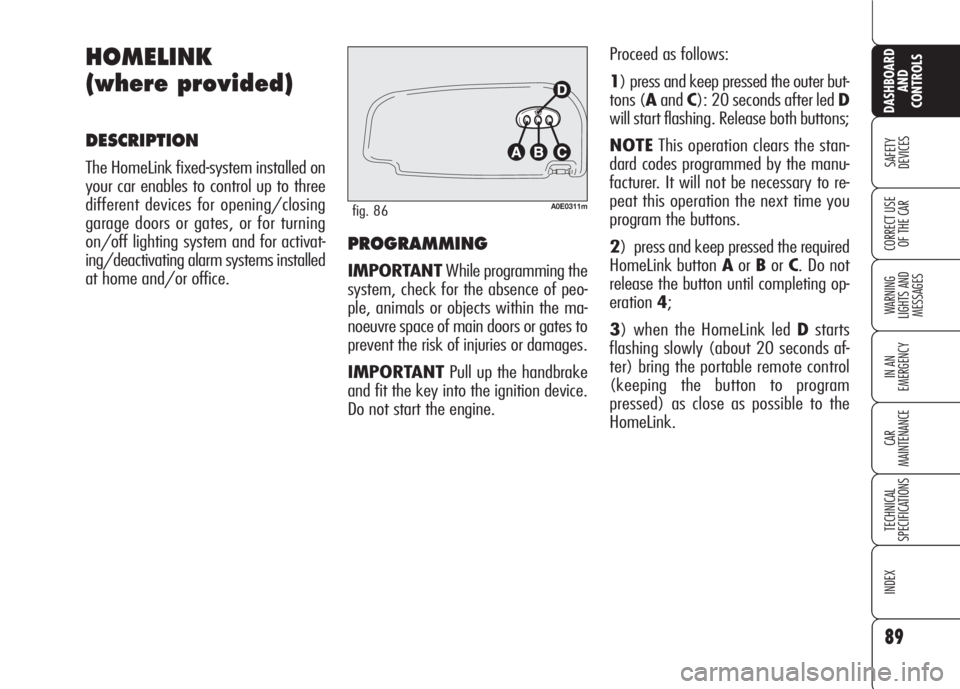
1) press and keep pressed the outer but-
tons (AandC): 20 seconds after led D
will start flashing. Release both buttons;
NOTEThis operation clears the stan-
dard codes programmed by the manu-
facturer. It will not be necessary to re-
peat this operation the next time you
program the buttons.
2) press and keep pressed the required
HomeLink button AorBorC. Do not
release the button until completing op-
eration4;
3) when the HomeLink led Dstarts
flashing slowly (about 20 seconds af-
ter) bring the portable remote control
(keeping the button to program
pressed) as close as possible to the
HomeLink.
89
SAFETY
DEVICES
WARNING
LIGHTS AND
MESSAGES
IN AN
EMERGENCY
CAR
MAINTENANCE
TECHNICAL
SPECIFICATIONS
INDEX
CORRECT USE
OF THE CAR
DASHBOARD
AND
CONTROLS
HOMELINK
(where provided)
DESCRIPTION
The HomeLink fixed-system installed on
your car enables to control up to three
different devices for opening/closing
garage doors or gates, or for turning
on/off lighting system and for activat-
ing/deactivating alarm systems installed
at home and/or office.
A0E0311mfig. 86
Page 93 of 303
Proceed as follows:
❒find the set-up button on the upper
side of the garage door/gate motor.
Colour and position may vary ac-
cording to the manufacturer (consult
the motor handbook);
❒press the motor set-up button (this
action will usually turn up the "set-
up" pilot light). After operation 2,
start to perform operation 3 within
30 seconds;
❒press the programmed button (Aor
BorC) and release it. Press again
the programmed button and then re-
lease it to end the operation. Certain
motors could require to repeat once
again the operation for concluding
the setting.
Now the motor should be up to recog-
nise the signal transmitted by HomeLink
and therefore to open/close the garage
door or the gate.
RE-PROGRAMMING ONE
SINGLE BUTTON
It is possible to programme another orig-
inal portable remote control on one
HomeLink button already programmed.
Previous programming will be cancelled.
IMPORTANTWhile programming the
system, check for the absence of peo-
ple, animals or objects within the ma-
noeuvre space of main doors or gates to
prevent the risk of injuries or damages.
IMPORTANTPull up the handbrake
and fit the key into the ignition device.
Do not start the engine.
Proceed as follows:
1) press and keep pressed the required
HomeLink button AorBorC. Do not
release the button until completing op-
eration3;
2) when the HomeLink led Dstarts
flashing slowly (about 20 seconds af-
ter) bring the portable remote control
(keeping the button to program
pressed) as close as possible to the
HomeLink. HomeLink can only work if the pro-
grammed alternate code is synchronised
with the system of the device (garage
door, gate, etc.).
IMPORTANTWhile synchronising the
system, check for the absence of peo-
ple, animals or objects within the ma-
noeuvre space of main doors or gates to
prevent the risk of injuries or damages.
IMPORTANTThe car shall be within
the range of the motor. Pull up the hand-
brake and fit the key into the ignition
device. Do not start the engine.
91
SAFETY
DEVICES
WARNING
LIGHTS AND
MESSAGES
IN AN
EMERGENCY
CAR
MAINTENANCE
TECHNICAL
SPECIFICATIONS
INDEX
CORRECT USE
OF THE CAR
DASHBOARD
AND
CONTROLS
Page 107 of 303

105
SAFETY
DEVICES
WARNING
LIGHTS AND
MESSAGES
IN AN
EMERGENCY
CAR
MAINTENANCE
TECHNICAL
SPECIFICATIONS
INDEX
CORRECT USE
OF THE CAR
DASHBOARD
AND
CONTROLS
Improper bonnet closing is indicated (on
certain versions) by the instrument pan-
el warning light
´(where provided), or
by symbol
Sand a message on the
display (see section “Warning lights and
messages”).
IMPORTANTAlways check that the
bonnet is closed properly to avoid its
opening while the car is travelling.
BONNET
TO OPEN THE BONNET
Proceed as follows:
❒pull lever A-fig. 98until hearing
the releasing click;
❒pull leverB-fig. 99and raise the
bonnet keeping the lever pulled
IMPORTANTBonnet raising is aided
by two gas springs. Do not tamper with
these springs and guide the bonnet
while raising it.
IMPORTANT Before opening the bon-
net, check that windscreen wiper arms
are not lifted from the windscreen.A0E0122mfig. 98
A0E0158mfig. 99
TO CLOSE THE BONNET
Lower the bonnet at approx. 20 cen-
timetres from the engine compartment
and then let it drop, ensuring that it is
fully closed and not just held in position
by the safety catch. If the bonnet does
not close properly, do not push it down
but open it again and repeat the above
procedure.
Carry out operations
only when the car is
stationary.
WARNING
For safety reasons the
bonnet must be closed
properly to avoid its opening
while the car is travelling.
Therefore, always check it is
properly closed and the catch
engaged. Should you notice
that the catch is not perfectly
engaged when travelling, stop
the car immediately and close
the bonnet.
WARNING
Page 112 of 303

110
SAFETY
DEVICES
WARNING
LIGHTS AND
MESSAGES
IN AN
EMERGENCY
CAR
MAINTENANCE
TECHNICAL
SPECIFICATIONS
INDEX
CORRECT USE
OF THE CAR
DASHBOARD
AND
CONTROLS
VDC SYSTEM
(Vehicle Dynamics
Control)
(where provided)
The VDC system is an electronic system
controlling the car stability in the event
of tyre grip loss.
The VDC system is therefore particular-
ly useful when grip conditions of the
road surfaces changes.
VDC SYSTEM
INTERVENTION
It is signalled by the blinking of the
warning light
áon the instrument pan-
el, to inform the driver that the car is
in critical stability and grip conditions.
TURNING THE VDC SYSTEM
ON/OFF
The VDC system is automatically acti-
vated when the engine is started. When
travelling, to turn the VDC off press the
ASR/ VDC button on the central console
fig. 103for 2 seconds. Turning off the
VDC will also turn off the ASR. Both func-
tions can be reactivated by pressing the
ASR/VDC button.
VDC system deactivation is indicated
by the instrument panel warning light
á(on certain versions a symbol is dis-
played) and by the circular led around
the ASR/VDC button.
If the VDC has been turned off when
travelling, at next engine start-up it will
turn on again automatically.
FAILURE WARNING LIGHTS
In the event of failure, the VDC system
is automatically disconnected and the
warning light
ácomes on with fixed
light on the instrument panel (on cer-
tain versions together with a message
on the display) (see section “Warning
lights and messages”). In this case con-
tact Alfa Romeo Authorized Services as
soon as possible.
A0E0026mfig. 103
Page 114 of 303

Failure warnings
System failure is indicated by the turn-
ing on of warning light
*(where pro-
vided) on the instrument panel (on cer-
tain versions together with the dedicat-
ed message on the display) (see section
“Warning lights and messages”).
IMPORTANTThe Hill Holder system
is not a parking brake. Never get out
of the car without engaging the hand-
brake, switching the engine off and en-
gaging the first gear.
ASR SYSTEM
(AntiSlip Regulation)
This system is an integral part of the VDC
system, it controls car drive and cuts in
automatically every time one or both dri-
ving wheels slip.
According to slipping conditions, two dif-
ferent control systems are activated:
❒ if slipping involves both driving
wheels, the ASR function intervenes
reducing the power transmitted by
the engine;
❒if slipping involves only one driving
wheel, the ASR system cuts in auto-
matically braking the wheel that is
slipping. This time elapsing without starting, the
system will deactivate automatically by
releasing gradually the brake force.
At releasing, the typical brake disen-
gagement noise indicating that the car
is going to move will be heard.
112
SAFETY
DEVICES
WARNING
LIGHTS AND
MESSAGES
IN AN
EMERGENCY
CAR
MAINTENANCE
TECHNICAL
SPECIFICATIONS
INDEX
CORRECT USE
OF THE CAR
DASHBOARD
AND
CONTROLS
Page 115 of 303
113
SAFETY
DEVICES
WARNING
LIGHTS AND
MESSAGES
IN AN
EMERGENCY
CAR
MAINTENANCE
TECHNICAL
SPECIFICATIONS
INDEX
CORRECT USE
OF THE CAR
DASHBOARD
AND
CONTROLS
The performance of the
system, in terms of ac-
tive safety should not induce
the driver to take pointless
and unnecessary risks. The
style of driving must in any
case always be adapted to the
conditions of the road surface,
visibility an traffic. Road safe-
ty is always the driver’s re-
sponsibility.
WARNINGThe action of the ASR is particularly help-
ful in the following circumstances:
❒slipping of the inner wheel due to the
effect of dynamic load changes or ex-
cessive acceleration;
❒ too much power transmitted to the
wheels also in relation to the condi-
tions of the road surface;
❒ acceleration on slippery, snowy or
frozen surfaces;
❒in the case of loss of grip on a wet
surface (aquaplaning).Switching the ASR system
on/off
ASR turns on automatically when turn-
ing the instrument panel on.
When travelling the ASR can be
switched off by pressing briefly the
ASR/VDC button on the central console.
When the ASR is switched off this is
shown by the lighting up of the
ASR/VDC button led (on versions fitted
with “Reconfigurable multifunction dis-
play” symbol Vwill also be dis-
played).
If the ASR is switched off when travel-
ling, it will turn on again automatically
the next time the engine is started.
When travelling on snowy roads with
snow chains, it may be helpful to turn
the ASR off: in fact, in these conditions,
slipping of the driving wheels when mov-
ing off makes it possible to obtain bet-
ter drive.
Page 116 of 303
Failure warnings
In the event of malfunctioning, the ASR
system is automatically disconnected
and on versions fitted with “Reconfig-
urable multifunction display” symbol
Vis displayed. In this case contact Al-
fa Romeo Authorized Services as soon
as possible.
114
SAFETY
DEVICES
WARNING
LIGHTS AND
MESSAGES
IN AN
EMERGENCY
CAR
MAINTENANCE
TECHNICAL
SPECIFICATIONS
INDEX
CORRECT USE
OF THE CAR
DASHBOARD
AND
CONTROLS
MSR system (engine braking
torque control)
It is an integral part of the ASR system
that in case of sudden gear shifting, cuts
in providing torque to the engine thus
preventing excessive driving wheel dri-
ve that, specially in poor grip conditions,
can lead to loss of stability.
For correct operation of
the ASR system, the
tyres must absolutely be of
the same brand and type on all
wheels, in normal conditions of
use, at the proper inflation
pressure values and, above all,
of type, brand and size speci-
fied (see paragraph “Wheels”
in section “Technical Specifica-
tions”).
WARNING
Page 117 of 303

115
SAFETY
DEVICES
WARNING
LIGHTS AND
MESSAGES
IN AN
EMERGENCY
CAR
MAINTENANCE
TECHNICAL
SPECIFICATIONS
INDEX
CORRECT USE
OF THE CAR
DASHBOARD
AND
CONTROLS
115
EOBD SYSTEM
(optional for
versions/markets
where applicable)
The EOBD system (European On Board
Diagnosis) allows continuous diagnosis
of the components of the car correlat-
ed with emissions.
It also alerts the driver, by turning on the
warning light
Uon the instrument pan-
el (on certain versions together with the
message on the display) (see section
“Warning lights and messages”), when
these conditions are no longer in peak
conditions.
If when fitting the key
into the ignition device,
the warning light
U
does not turn on or if, while
travelling it turns on glowing
steadily or flashing, contact Al-
fa Romeo Authorized Services
as soon as possible. Warning
light
Uoperation can be
checked by means of special
equipment by traffic agents. Al-
ways comply with the traffic
regulations in force in the coun-
try where you are travelling.
The objective is:
❒ to keep system efficiency under con-
trol;
❒ to warn when a fault causes emission
levels to increase;
❒to warn of the need to replace dete-
riorated components.
The system also has a diagnostic con-
nector that can be interfaced with ap-
propriate tools, which makes it possible
to read the error codes stored in the con-
trol unit, together with a series of spe-
cific parameters for engine operation
and diagnosis. This check can also be
carried out by the traffic police.
IMPORTANTAfter eliminating the in-
convenience, to check the system com-
pletely, Alfa Romeo Authorized Services
are obliged to run a bench test and, if
necessary, road tests which may also
call for a long journey.