sensor Alfa Romeo 166 2006 Owner handbook (in English)
[x] Cancel search | Manufacturer: ALFA ROMEO, Model Year: 2006, Model line: 166, Model: Alfa Romeo 166 2006Pages: 272, PDF Size: 4.17 MB
Page 12 of 272
11
Sit comfortably in your vehicle and carefully read through the fol-
lowing pages.
You will immediately recognize the parts described and rapidly get
to know the controls and devices fitted to your vehicle.STR (SPORT THROTTLE RESPONSE) SYSTEM.................................................63
CONSTANT SPEED REGULATOR (CRUISE CONTROL)
...................................64
PARKING SENSORS
...............................................................................................67
INSTRUMENT PANEL
.............................................................................................68
CLIMATE CONTROL
................................................................................................80
CLIMATE CONTROL UNIT
.....................................................................................83
ADDITIONAL HEATER
............................................................................................91
CONTROLS
................................................................................................................93
INTERNAL FITTINGS
..............................................................................................96
SUNROOF
.................................................................................................................103
LUGGAGE COMPARTMENT
..................................................................................105
BONNET
....................................................................................................................109
HEADLIGHTS
............................................................................................................110
EOBD SYSTEM
........................................................................................................113
ABS
.............................................................................................................................114
VDC AND ASR SYSTEMS
.......................................................................................117
SOUND SYSTEM
......................................................................................................122
REFUELLING
............................................................................................................124
FUEL CUT-OFF SWITCH
........................................................................................127
ENVIRONMENTAL PROTECTION
.........................................................................129 DASHBOARD
................................................................................................page 12
ALFA ROMEO I.C.S. SYSTEM: CONTROLS ON STEERING WHEEL
. ..........14
THE ALFA ROMEO CODE SYSTEM
......................................................................16
ELECTRONIC ALARM
..............................................................................................22
REMOTE CONTROL DOOR LOCKING SYSTEM
................................................26
IGNITION DEVICE
...................................................................................................26
DOORS
.......................................................................................................................28
SEATS
.........................................................................................................................31
STEERING WHEEL ADJUSTMENT
.......................................................................36
ADJUSTING THE REAR-VIEW MIRRORS
..........................................................36
POWER WINDOWS
................................................................................................38
SEAT BELTS
...............................................................................................................40
CARRYING CHILDREN SAFELY
............................................................................45
FRONT AND SIDE AIR BAGS
...............................................................................50
LIGHT SWITCHES & STEERING WHEEL LEVERS
............................................57
GETTING TO KNOW YOUR CAR
Page 14 of 272
13
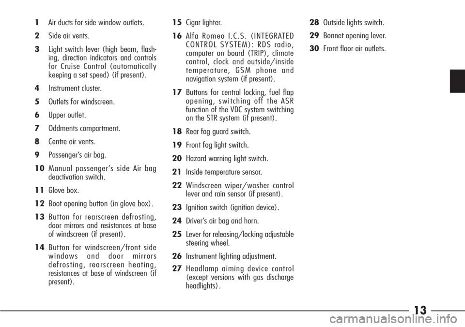
1Air ducts for side window outlets.
2Side air vents.
3Light switch lever (high beam, flash-
ing, direction indicators and controls
for Cruise Control (automatically
keeping a set speed) (if present).
4Instrument cluster.
5Outlets for windscreen.
6Upper outlet.
7Oddments compartment.
8Centre air vents.
9Passenger’s air bag.
10Manual passenger’s side Air bag
deactivation switch.
11Glove box.
12Boot opening button (in glove box).
13Button for rearscreen defrosting,
door mirrors and resistances at base
of windscreen (if present).
14Button for windscreen/front side
windows and door mirrors
defrosting, rearscreen heating,
resistances at base of windscreen (if
present).15Cigar lighter.
16Alfa Romeo I.C.S. (INTEGRATED
CONTROL SYSTEM): RDS radio,
computer on board (TRIP), climate
control, clock and outside/inside
temperature, GSM phone and
navigation system (if present).
17Buttons for central locking, fuel flap
opening, switching off the ASR
function of the VDC system switching
on the STR system (if present).
18Rear fog guard switch.
19Front fog light switch.
20Hazard warning light switch.
21Inside temperature sensor.
22Windscreen wiper/washer control
lever and rain sensor (if present).
23Ignition switch (ignition device).
24Driver’s air bag and horn.
25Lever for releasing/locking adjustable
steering wheel.
26Instrument lighting adjustment.
27Headlamp aiming device control
(except versions with gas discharge
headlights).28Outside lights switch.
29Bonnet opening lever.
30Front floor air outlets.
Page 19 of 272
18
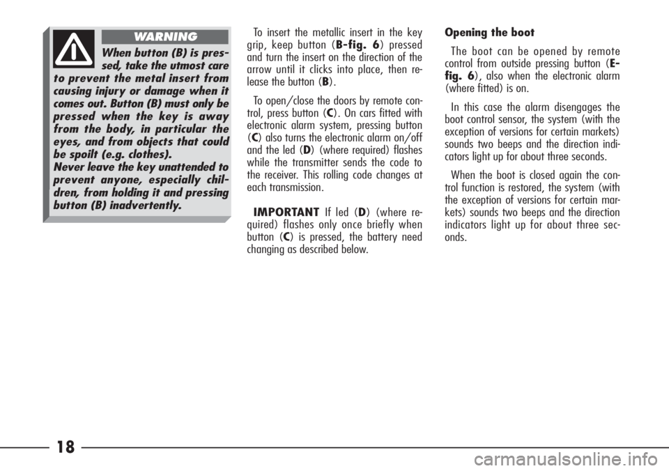
To insert the metallic insert in the key
grip, keep button (B-fig. 6) pressed
and turn the insert on the direction of the
arrow until it clicks into place, then re-
lease the button (B).
To open/close the doors by remote con-
trol, press button (C). On cars fitted with
electronic alarm system, pressing button
(C) also turns the electronic alarm on/off
and the led (D) (where required) flashes
while the transmitter sends the code to
the receiver. This rolling code changes at
each transmission.
IMPORTANTIf led (D) (where re-
quired) flashes only once briefly when
button (C) is pressed, the battery need
changing as described below.Opening the boot
The boot can be opened by remote
control from outside pressing button (E-
fig. 6), also when the electronic alarm
(where fitted) is on.
In this case the alarm disengages the
boot control sensor, the system (with the
exception of versions for certain markets)
sounds two beeps and the direction indi-
cators light up for about three seconds.
When the boot is closed again the con-
trol function is restored, the system (with
the exception of versions for certain mar-
kets) sounds two beeps and the direction
indicators light up for about three sec-
onds.
When button (B) is pres-
sed, take the utmost care
to prevent the metal insert from
causing injury or damage when it
comes out. Button (B) must only be
pressed when the key is away
from the body, in particular the
eyes, and from objects that could
be spoilt (e.g. clothes).
Never leave the key unattended to
prevent anyone, especially chil-
dren, from holding it and pressing
button (B) inadvertently.
WARNING
Page 23 of 272
22 ELECTRONIC ALARM
(optional for versions/markets where
applicable)
DESCRIPTION
The system certified in accordance with
EC Directive 95/56 comprises: transmit-
ter , receiver, control unit with siren and
volumetric sensors. The electronic alarm
is controlled by the receiver and it is
turned on and off through the remote
control incorporated in the key which
sends the crypted, variable code. The
electronic alarm monitors: unlawful open-
ing of the doors, bonnet and boot
(perimetral protection), operation of the
ignition key, battery and emergency key
cable cutting, the presence of moving
bodies in the passenger compartment
(volumetric protection) and operates the
central door locking system. Is also
makes it possible to cut off volumetric
protection and/or the siren.
IMPORTANTThe engine inhibitor
function is guaranteed by the Alfa Romeo
CODE system which is activated automati-
cally when the ignition key is removed
from the lock.
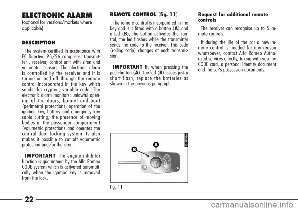
REMOTE CONTROL (fig. 11)
The remote control is incorporated in the
key and it is fitted with a button (A) and
a led (B); the button activates the con-
trol, the led flashes while the transmitter
sends the code to the receiver. This code
(rolling code) changes at each transmis-
sion.
IMPORTANTIf, when pressing the
push-button (A), the led (B) issues just a
short flash, replace the batteries as
shown in the previous paragraph.Request for additional remote
controls
The receiver can recognise up to 5 re-
mote controls.
If during the life of the car a new re-
mote control is needed for any reason
whatsoever, contact Alfa Romeo Autho-
rized services directly, taking with you the
CODE card, a personal identity document
and the car’s possession documents.
fig. 11
1013PGSm
Page 25 of 272
24
3 flashes: right rear door
4 flashes: left rear door
5 flashes: volumetric sensors
6 flashes: bonnet
7 flashes: boot
8 flashes: tampering with car starting
cables
9 flashes: tampering with battery cables
or cutting emergency key cables
10 flashes: at least three causes of alarm.WHEN THE ALARM IS
TRIGGERED
When the alarm is engaged it will sound
when:
– One of the doors, the bonnet or the
boot is opened.
– The battery is disconnected or the
electric cables are cut, or the emergency
key cables are cut.
– Intrusion into the passenger compart-
ment, e.g. window being broken (volu-
metric protection).
– Attempt to start the engine (key at
MAR).
Depending on the markets, the trigger-
ing of the alarm will activate the siren
and the hazard warning lights (for about
26 seconds). The methods of operation
and the number of cycles may vary de-
pending on the versions/markets. How-
ever a maximum number of cycles is fore-
seen. Once the alarm cycle has come to
an end the system will return to its nor-
mal monitoring state.
SWITCHING OFF THE ALARM
To switch off the alarm, press the re-
mote control button on the key. If the
alarm does not turn off due to a flat re-
mote control battery or system fault,
open the door after unlocking with the
lock key, then place the key in the igni-
tion switch and turn it to MAR.
To turn on the alarm again, turn the key
toSTOPand remove it, then press the
remote control button after leaving the
car and shutting the doors. If the alarm
does not turn on and the led on the re-
mote control gives only one brief flash
while the led on the dashboard stays on
glowing steadily for about 2 minutes, the
key battery should be replaced by a new
one of the equivalent type on sale c/o
normal retailers. To change the battery
follow the instructions given at paragraph
“Key battery change” on previous pages.
If it is not possible to switch on the
alarm with a new remote control battery,
contact Alfa Romeo Authorised Services
to have the system checked.
Page 43 of 272
42
PRETENSIONERS
To increase the efficiency of the front
seat belts, the Alfa 166is fitted with
pretensioners.
These devices “feel”, through a sensor,
that a violent crash is in progress and
rewind the seat belts a few centimetres.
In this way they ensure that the seat belt
adheres perfectly to the wearer before
the restraining action begins.
The seat belt locks to indicate that the
device has intervened; the seat belt can-
not be drawn back up even when guiding
it manually.
IMPORTANTTo obtain the highest
degree of protection from the action of
the pretensioning device, wear the seat
belt keeping it firmly close to the chest
and pelvis.
A small amount of smoke may be pro-
duced. This smoke is in no way toxic and
presents no fire hazard.The pretensioner does not require any
maintenance or greasing. Anything that
modifies its original conditions invalidates
its efficiency. If due to unusual natural
events (floods, sea storm, etc.) the de-
vice has been affected by water and
mud, it must necessarily be replaced.
After adjustment, always
check that the slider is
anchored in one of the positions
provided. To do this, with the but-
ton (A-fig. 52) released, exert a
further pressure to allow the an-
chor device to catch if release did
not take place at one of the preset
positions.
WARNING
The pretensioner can only
be used once. After a col-
lision that has triggered it, have it
replaced at an Alfa Romeo Autho-
rized Services. The validity of the
device is 10 years starting from
the date of production, the preten-
sioners should be replaced at an
Alfa Romeo Authorized Services as
this date approaches.
WARNING
This precaution could greatly reduce the
risk of injury in case of collision.
Correct adjustment is obtained when the
belt passes half way between the end of
the shoulder and the neck.
4 different adjustments in height are
provided.
To adjust the attachment raise or lower
the grip (A-fig. 52) and ring (B-
fig. 52) to one of the set positions.
Page 52 of 272
51
The front Air bag (driver’s and passen-
ger’s) is a device designed to protect the
occupants in the event of head-on colli-
sion of medium-high severity by the inter-
position of the cushion between the occu-
pant and the steering wheel or dash-
board.
In the event of a crash, the electronic
control unit processes the signals leading
from a deceleration sensor and when nec-
essary, triggers inflation of the cushion.
The cushion inflates instantly as a pro-
tective barrier between the occupants’
bodies and the structures which could
cause injury. The cushion deflates imme-
diately afterwards.
The front Air bag (driver and passenger)
has been designed to protect the occu-
pants in the event of head-on crashes of
medium-high severity, by placing the
cushion between the occupant and the s-
teering wheel or dashboard.In case of crash, a person not wearing
the seat belt moves forward and may
come into contact with the cushion while
it is still inflating. Under this circumstance
the protection offered by the air bag is re-
duced.
Front air bags are designed to protect
car’s occupants in front crashes and there-
fore non-activation in other types of colli-
sions (side collisions, rear-end shunts, roll-
overs, etc…) is not a system malfunc-
tion.In collisions against highly deformable
or mobile objects (such as road signs,
heaps of gravel or snow, parked vehicles,
etc.), in rear crashes (such as bumps
from behind by another vehicle), side im-
pacts, and in case of wedging under other
vehicles or protective barriers (for exam-
ple under a truck or guard rail), the Air
bag is not triggered as it offers no addi-
tional protection compared with the seat
belts, consequently, it would be pointless.
Therefore the failure to be triggered
does not mean that the system is not
working properly.
Page 55 of 272

54
SIDE AIR BAGS
(SIDE BAG -
FRONT WINDOW BAG)
Side air bags have the task of increasing
protection of the occupants in the event of
a side crash of medium-high severity.
They are made of two types of instantly-
inflating cushions:
– side bags, housed in the back rest of
the front seats; with this solution it is always
possible to have the air bag (cushion) in the
optimum position in relation to the passen-
ger, regardless of the adjustment of the
seat;
– front window bags, which are “curtain”
cushions, are housed behind the side roof
linings; this solution designed to protect the
head, makes it possible to offer the highest
degree of protection to the front occupants
in the event of a side crash, thanks to the
wide cushion inflation surface.
In the event of a side crash the electronic
control unit processes the signals leading
from a deceleration sensor and, when nec-
essary, triggers inflation of the air bags.The bags inflate instantaneously, setting
themselves between the body of the front
passengers and the car door. The bags de-
flate immediately afterwards.
In the event of minor side crashes (for
which the restraining action of the seat belts
is sufficient), the air bags are not deployed.
Also in this case it is of vital importance to
wear the seat belts since in case of side
crash they guarantee proper positioning of
the occupant and prevent the occupant to
be pitched out of the car in case of violent
crashes.
Therefore the side air bags do not replace
but are complementary to the use of belts,
which you are recommended to always
wear, as specified by law in Europe and
most non-European countries.
Operation of the side air bags and front
window bags is not disabled by the front air
bag deactivation switch, as described in the
previous paragraphs.IMPORTANTIn the event of side
crash, you can obtain the best protection
by the system keeping a correct position
on the seat, thus allowing correct front
window bag unfolding.
WARNING Never rest
head, arms and elbows
on the door, on the windows and
in the front window bag area to
prevent possible injuries during the
inflation phase.
WARNING
IMPORTANTThe front and/or side
air bags may be activated if the car is
subjected to heavy shocks or accidents
that involve the underbody area, such as
for example violent bumps against steps,
pavements or fixed obstacles on the
ground, falling into big holes or bumpy
roads.
Page 62 of 272
61
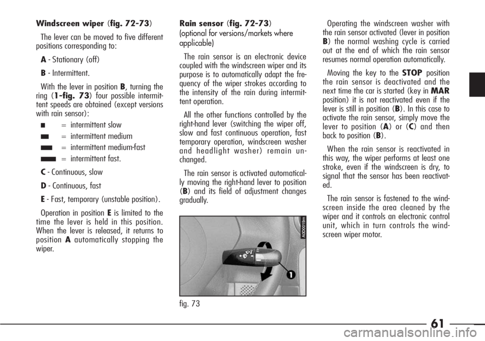
Windscreen wiper (fig. 72-73)
The lever can be moved to five different
positions corresponding to:
A- Stationary (off)
B- Intermittent.
With the lever in position B, turning the
ring (1-fig. 73) four possible intermit-
tent speeds are obtained (except versions
with rain sensor):
■= intermittent slow
■■= intermittent medium
■■■= intermittent medium-fast
■■■■= intermittent fast.
C- Continuous, slow
D- Continuous, fast
E- Fast, temporary (unstable position).
Operation in position Eis limited to the
time the lever is held in this position.
When the lever is released, it returns to
positionAautomatically stopping the
wiper.Rain sensor (fig. 72-73)
(optional for versions/markets where
applicable)
The rain sensor is an electronic device
coupled with the windscreen wiper and its
purpose is to automatically adapt the fre-
quency of the wiper strokes according to
the intensity of the rain during intermit-
tent operation.
All the other functions controlled by the
right-hand lever (switching the wiper off,
slow and fast continuous operation, fast
temporary operation, windscreen washer
and headlight washer) remain un-
changed.
The rain sensor is activated automatical-
ly moving the right-hand lever to position
(B) and its field of adjustment changes
gradually.Operating the windscreen washer with
the rain sensor activated (lever in position
B) the normal washing cycle is carried
out at the end of which the rain sensor
resumes normal operation automatically.
Moving the key to the STOPposition
the rain sensor is deactivated and the
next time the car is started (key in MAR
position) it is not reactivated even if the
lever is still in position (B). In this case to
activate the rain sensor, simply move the
lever to position (A) or (C) and then
back to position (B).
When the rain sensor is reactivated in
this way, the wiper performs at least one
stroke, even if the windscreen is dry, to
signal that the sensor has been reactivat-
ed.
The rain sensor is fastened to the wind-
screen inside the area cleaned by the
wiper and it controls an electronic control
unit, which in turn controls the wind-
screen wiper motor.
A0D0019m
fig. 73
Page 63 of 272
62
At each start the rain sensor automati-
cally (in about 2 minutes) stabilises at a
temperature of about 40°C to eliminate
any condensation from the control surface
and prevent the formation of ice.
The rain sensor is capable of detecting
and adapting automatically to the pres-
ence of the following particular conditions
which call for different sensitivity:
– impurities on the control surface
(saline deposits, dirt, etc.)
– streaks of water caused by partial
wear of the windscreen wiper
– difference between day and night
(the human eye is more disturbed during
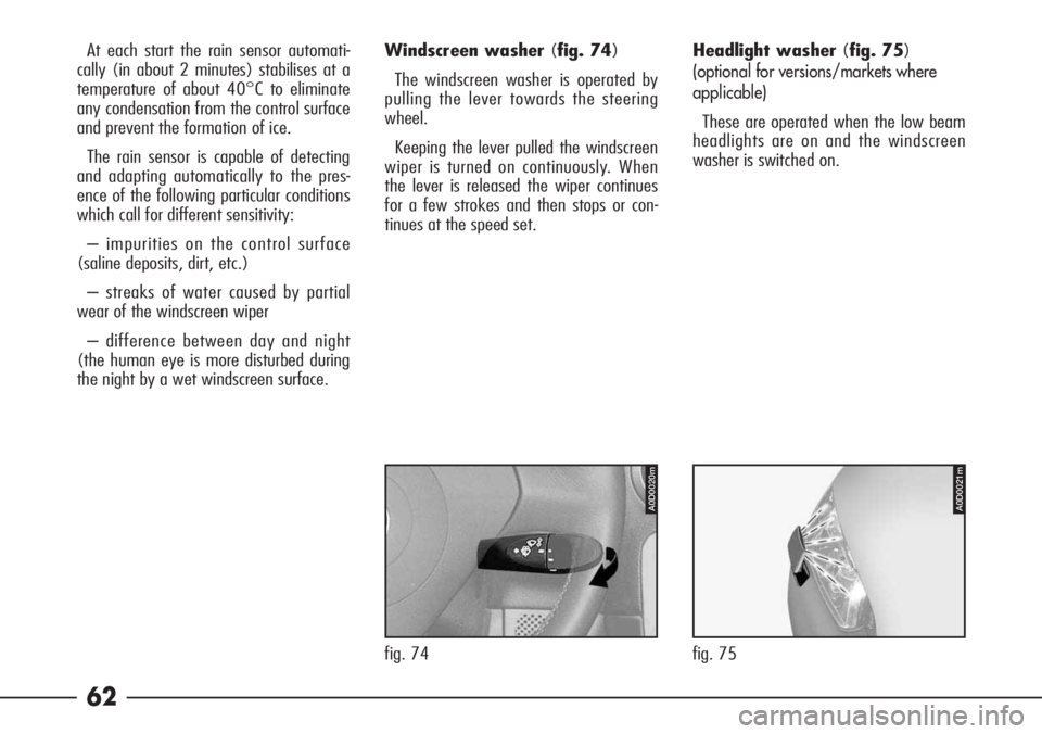
the night by a wet windscreen surface.Headlight washer (fig. 75)
(optional for versions/markets where
applicable)
These are operated when the low beam
headlights are on and the windscreen
washer is switched on. Windscreen washer (fig. 74)
The windscreen washer is operated by
pulling the lever towards the steering
wheel.
Keeping the lever pulled the windscreen
wiper is turned on continuously. When
the lever is released the wiper continues
for a few strokes and then stops or con-
tinues at the speed set.
A0D0020m
fig. 74
A0D0021m
fig. 75