check engine Alfa Romeo 166 2006 Owner handbook (in English)
[x] Cancel search | Manufacturer: ALFA ROMEO, Model Year: 2006, Model line: 166, Model: Alfa Romeo 166 2006Pages: 272, PDF Size: 4.17 MB
Page 212 of 272
211
PROTECTIVE SHIELD UNDER
ENGINE
The car is fitted with a protective shield
under the engine.
IMPORTANTWhen changing the en-
gine oil and filter, checking and changing
the gearbox and differential oil, this pro-
tection should be removed. This operation
should be carried out by Alfa Romeo Au-
thorized Services.
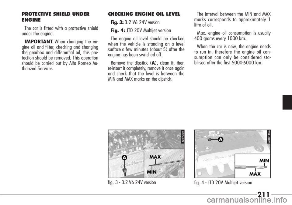
CHECKING ENGINE OIL LEVEL
Fig. 3:3.2 V6 24V version
Fig. 4:JTD 20V Multijet version
The engine oil level should be checked
when the vehicle is standing on a level
surface a few minutes (about 5) after the
engine has been switched off.
Remove the dipstick (A), clean it, then
re-insert it completely, remove it once again
and check that the level is between the
MIN and MAX marks on the dipstick.The interval between the MIN and MAX
marks corresponds to approximately 1
litre of oil.
Max. engine oil consumption is usually
400 grams every 1000 km.
When the car is new, the engine needs
to run in, therefore the engine oil con-
sumption can only be considered sta-
bilised after the first 5000-6000 km.
fig. 3 - 3.2 V6 24V version
424PGSm
fig. 4 - JTD 20V Multijet version
A0D0113m
Page 213 of 272
212
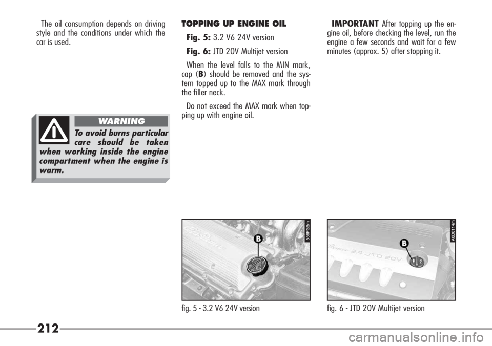
fig. 6 - JTD 20V Multijet version
A0D0114m
The oil consumption depends on driving
style and the conditions under which the
car is used.
fig. 5 - 3.2 V6 24V versionTOPPING UP ENGINE OIL
Fig. 5:3.2 V6 24V version
Fig. 6:JTD 20V Multijet version
When the level falls to the MIN mark,
cap (B) should be removed and the sys-
tem topped up to the MAX mark through
the filler neck.
Do not exceed the MAX mark when top-
ping up with engine oil.IMPORTANT After topping up the en-
gine oil, before checking the level, run the
engine a few seconds and wait for a few
minutes (approx. 5) after stopping it.
To avoid burns particular
care should be taken
when working inside the engine
compartment when the engine is
warm.
WARNING
556PGSm
Page 215 of 272
214
The antifreeze mixture
contained in the cooling
circuit guarantees pro-
tection down to –35°C.
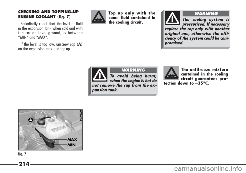
CHECKING AND TOPPING-UP
ENGINE COOLANT
(fig. 7)
Periodically check that the level of fluid
in the expansion tank when cold and with
the car on level ground, is between
“MIN” and “MAX”.
If the level is too low, unscrew cap (A)
on the expansion tank and top-up. Top up only with the
same fluid contained in
the cooling circuit.
A0D0100m
fig. 7
The cooling system is
pressurised. If necessary
replace the cap only with another
original one, otherwise the effi-
ciency of the system could be com-
promised.
WARNING
To avoid being burnt,
when the engine is hot do
not remove the cap from the ex-
pansion tank.
WARNING
Page 216 of 272
215
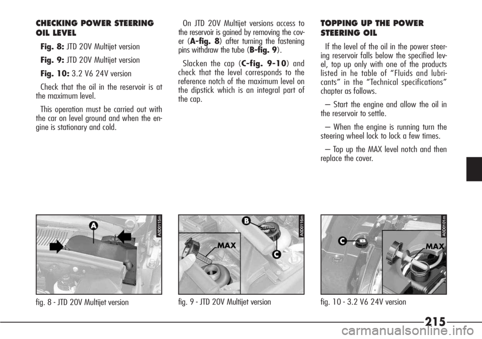
CHECKING POWER STEERING
OIL LEVEL
Fig. 8:JTD 20V Multijet version
Fig. 9:JTD 20V Multijet version
Fig. 10:3.2 V6 24V version
Check that the oil in the reservoir is at
the maximum level.
This operation must be carried out with
the car on level ground and when the en-
gine is stationary and cold.
fig. 8 - JTD 20V Multijet versionfig. 9 - JTD 20V Multijet versionfig. 10 - 3.2 V6 24V version On JTD 20V Multijet versions access to
the reservoir is gained by removing the cov-
er (A-fig. 8) after turning the fastening
pins withdraw the tube (B-fig. 9).
Slacken the cap (C-fig. 9-10) and
check that the level corresponds to the
reference notch of the maximum level on
the dipstick which is an integral part of
the cap.
TOPPING UP THE POWER
STEERING OIL
If the level of the oil in the power steer-
ing reservoir falls below the specified lev-
el, top up only with one of the products
listed in he table of “Fluids and lubri-
cants” in the “Technical specifications”
chapter as follows.
– Start the engine and allow the oil in
the reservoir to settle.
– When the engine is running turn the
steering wheel lock to lock a few times.
– Top up the MAX level notch and then
replace the cover.
A0D0115mA0D0101mA0D0116m
Page 217 of 272
When the cap (B) is
screwed off the reser-
voir ensure that the
electrical connections are not dis-
connected. Make sure that the
highly corrosive brake fluid
does not drip onto the paint-
work. If it does, wash it off
immediately with water.
IMPORTANT Contact Alfa Romeo Au-
thorized Services for maintenance and re-
pair operations.Oil consumption is very
low; if topping up again
is needed shortly after-
wards, have the system checked
for possible leaks by Alfa Romeo
Authorized services.
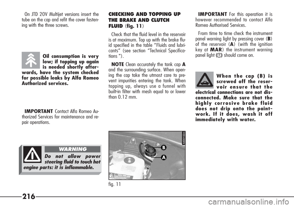
CHECKING AND TOPPING UP
THE BRAKE AND CLUTCH
FLUID
(fig. 11)
Check that the fluid level in the reservoir
is at maximum. Top up with the brake flu-
id specified in the table “Fluids and lubri-
cants” (see section “Technical Specifica-
tions ").
NOTEClean accurately the tank cap A
and the surrounding surface. When open-
ing the cap take the utmost care to pre-
vent impurities entering the tank. When
topping up, always use a funnel with
built-in filter with mesh equal to or lower
than 0.12 mm. On JTD 20V Multijet versions insert the
tube on the cap and refit the cover fasten-
ing with the three screws.
Do not allow power
steering fluid to touch hot
engine parts: it is inflammable.
WARNING
A0D0102m
fig. 11
216
IMPORTANTFor this operation it is
however recommended to contact Alfa
Romeo Authorised Services.
From time to time check the instrument
panel warning light by pressing cover (B)
of the reservoir (A) (with the ignition
key at MAR) the instrument warning
panel light
xshould come on.
Page 220 of 272
219
DUST/POLLEN FILTER
The filter mechanically/electrostatically
filters the air provided that the windows
are shut.
The dust/pollen filter should be checked
over once a year by Alfa Romeo Autho-
rized Service station preferably at the be-
ginning of the summer.
If the vehicle is habitually driven in
cities, motorways or on dusty roads the
system should be checked over more of-
ten than specified in the Programmed
Maintenance Schedule.
IMPORTANT If the filter is not re-
placed the efficiency of the climate con-
trol system may be seriously compro-
mised.
DIESEL FILTER
DRAINING CONDENSATION
WATER
BATTERY
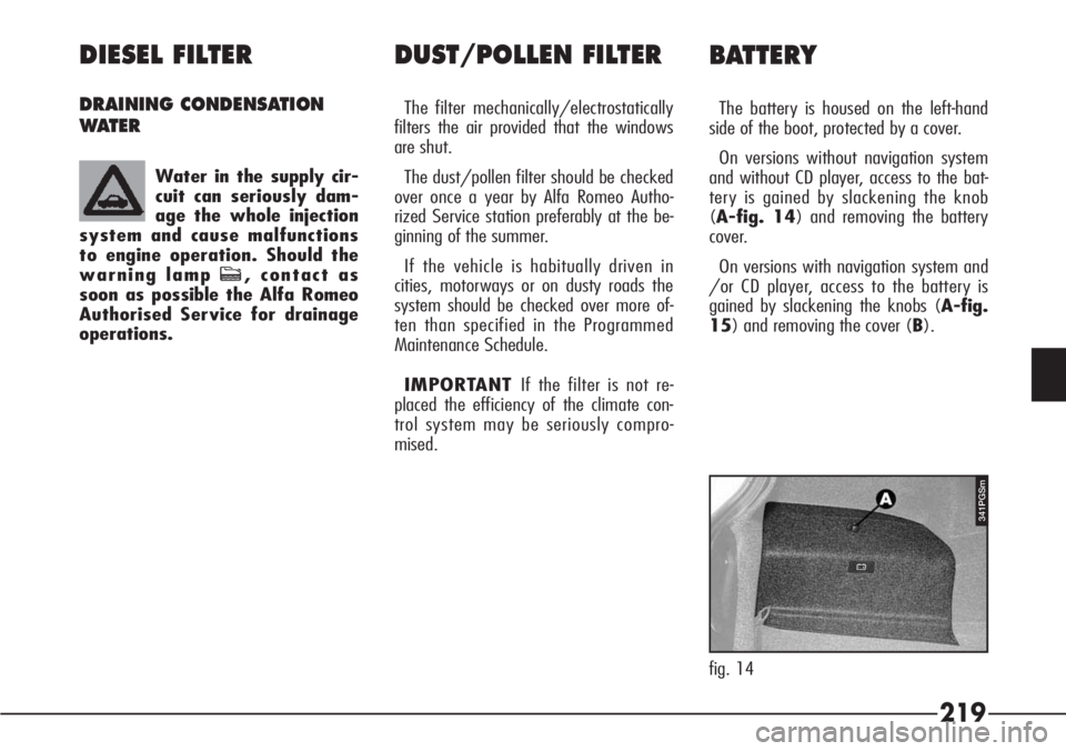
The battery is housed on the left-hand
side of the boot, protected by a cover.
On versions without navigation system
and without CD player, access to the bat-
tery is gained by slackening the knob
(A-fig. 14) and removing the battery
cover.
On versions with navigation system and
/or CD player, access to the battery is
gained by slackening the knobs (A-fig.
15) and removing the cover (B). Water in the supply cir-
cuit can seriously dam-
age the whole injection
system and cause malfunctions
to engine operation. Should the
warning lamp c, contact as
soon as possible the Alfa Romeo
Authorised Service for drainage
operations.
fig. 14
341PGSm
Page 223 of 272
222
– Before doing any work on the electric
system, disconnect the battery negative
terminal.
If after purchasing the car, you wish to
install electrical accessories which need a
permanent electrical supply (alarm,
hands-free phone, radio-navigator with
satellite anti-theft function, etc.) contact
Authorised Alfa Romeo Services whose
qualified personnel, in addition to sug-
gesting the most suitable devices from
Lineaccessori will be able to evaluate the
total electrical absorption, checking
whether the car’s electric system is able
to support the load required or whether a
battery with higher capacity is necessary.
In fact, these devices continue to absorb
current with the ignition key off (car
parked, engine off) and may gradually
drain the battery. IMPORTANT A battery kept at below
50% of its capacity is damaged by sul-
phation, the capacity is reduced and start-
ing is difficult, there is also more possibili-
ty of freezing (this can occur at –10°C).
In the event of a prolonged stop, refer to
“Vehicle inactivity”.
USEFUL HINTS TO EXTEND
THE LIFE OF YOUR BATTERY
To avoid quickly draining the battery
and to preserve its operating conditions
over the course of time, carefully follow
the instructions below.
– The terminals must always be tight-
ened.
– As far as possible avoid keeping ser-
vices on for a long time with the engine
stopped (radio, hazard warning lights,
parking lights, etc.).
– When leaving the vehicle parked in a
garage, make sure that the doors, bon-
net, boot and interior lids are properly
shut to prevent lights from staying on.
The fluid contained in the
battery is poisonous and
corrosive. Avoid contact with the
skin or eyes. The battery should be
charged in a ventilated place away
from naked flames or possible
sources of sparks: danger of ex-
plosion and fire.
WARNING
Never attempt to charge
a frozen battery before
thawing it, the danger of explosion
exists. If it has frozen, always
check that the inside elements are
not broken (risk of short circuit)
and that the body is not cracked,
with the risk of acid coming out
which is poisonous and corrosive.
WARNING
Page 224 of 272
223
– If electrical welding is to be carried
out on the body of the vehicle the elec-
tronic control units must be disconnected
or removed if the work involves the pro-
duction of high temperatures.The total absorption of these accessories
(standard and installed later) must be
0.6 mA x Ah (of the battery), as shown
in the table below:
BatteryMaximum permissible loadless absorption
100 Ah 60 mA
You are also reminded that services with
high current absorption activated by the
user, such as bottle warmers, vacuum
cleaners, cellular telephone, mini refriger-
ator, etc. accelerate the battery drainage
process if they are powered with the en-
gine not running.
IMPORTANT It should also be noted
that improper branches on connectors of
the electric wiring for installing additional
equipment is dangerous, particularly if
safety devices are involved.
ELECTRONIC
CONTROL UNITS
With normal use of the vehicle no par-
ticular precautions need to be taken.
If interventions are to be carried out on
the electrical system or emergency start-
ing the following must be heeded:
– Always switch off the engine before
disconnecting the battery from the electri-
cal system.
– If battery charging is necessary dis-
connect it from the electric system.
– When starting in an emergency only
an auxiliary battery must be used and not
a battery charger.
– Check that the polarity is correct and
that the connections between the battery
and the electrical system are sound.
– Before connecting or disconnecting
the terminals of the electronic units en-
sure that the ignition key is not in the
MARposition.
– Do not check for current in the cables
by short-circuiting the ends.
If additional systems are
to be installed on the ve-
hicle the danger of incorrectly tak-
ing branches from the electrical
wires cannot be emphasized too
strongly especially if devices es-
sential to the safety of the vehi-
cle and its occupants are involved
(ignition, injection, ABS ...). The in-
correct installation of radio sys-
tems, electronic theft alarms, ra-
diotelephones etc. can interfere
with the electronic control units and
compromises the warranty cover.
For these interventions we re-com-
mend that you contact Alfa Romeo
Authorized Services.The loadless
absorption of all the accessories in-
stalled in the after market must
not exceed 20 mA (reading with
the vehicle stationary).
WARNING
Page 225 of 272
224
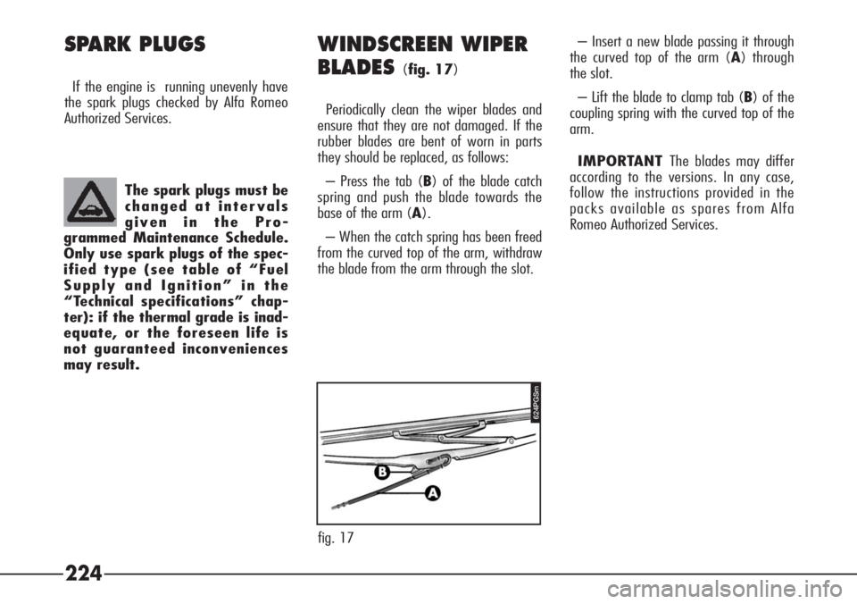
– Insert a new blade passing it through
the curved top of the arm (A) through
the slot.
– Lift the blade to clamp tab (B) of the
coupling spring with the curved top of the
arm.
IMPORTANT The blades may differ
according to the versions. In any case,
follow the instructions provided in the
packs available as spares from Alfa
Romeo Authorized Services.WINDSCREEN WIPER
BLADES
(fig. 17)
Periodically clean the wiper blades and
ensure that they are not damaged. If the
rubber blades are bent of worn in parts
they should be replaced, as follows:
– Press the tab (B) of the blade catch
spring and push the blade towards the
base of the arm (A).
– When the catch spring has been freed
from the curved top of the arm, withdraw
the blade from the arm through the slot. The spark plugs must be
changed at intervals
given in the Pro-
grammed Maintenance Schedule.
Only use spark plugs of the spec-
ified type (see table of “Fuel
Supply and Ignition” in the
“Technical specifications” chap-
ter): if the thermal grade is inad-
equate, or the foreseen life is
not guaranteed inconveniences
may result.
SPARK PLUGS
If the engine is running unevenly have
the spark plugs checked by Alfa Romeo
Authorized Services.
624PGSm
fig. 17
Page 226 of 272
225
– Application of enamels with greater
resistance to atmospheric pollutants.
– Adoption of “open” boxed parts to
prevent condensation from triggering cor-
rosion from the inside.
The underbody is treated with the appli-
cation of a special protective material.
If this protective layer requires restora-
tion the exhaust system, lambda probe
and catalytic converter must be left free
of any wax, oil, plastic and/or inflamma-
ble product.
This should therefore be carried out by
Alfa Romeo Authorized Services.SPRAY JETS
Make sure that the windscreen and
headlight washer jets deliver a jet of fluid
which is adequate and correctly directed.
If the spray devices are not working
check that the supply circuit is not
blocked. If necessary unclog the nozzles
using a needle.
BODYWORK
PROTECTION FROM
ATMOSPHERIC AGENTS
Alfa Romeo employs manufacturing
technologies which are designed to pro-
tect the bodywork against chemical corro-
sion caused by various factors, for exam-
ple:
– atmospheric pollution.
– Salty air and humidity (coastal areas,
hot-humid climates).
– Road surfaces covered with salt and
de-icing products during the winter.
To further increase resistance against
corrosion the following procedures have
been adopted:
– painting system and paint products
which render the vehicle particularly resis-
tant to corrosion and abrasion.
– Wide use of sheet metal which is ex-
tremely resistant to corrosion.
– Spraying of the underbody, engine
bay, wheel arches and boxed parts with
suitable products which adhere strongly
to the metal parts and have a high pro-
tection capability.