clock Alfa Romeo 166 2006 Owner handbook (in English)
[x] Cancel search | Manufacturer: ALFA ROMEO, Model Year: 2006, Model line: 166, Model: Alfa Romeo 166 2006Pages: 272, PDF Size: 4.17 MB
Page 14 of 272
13
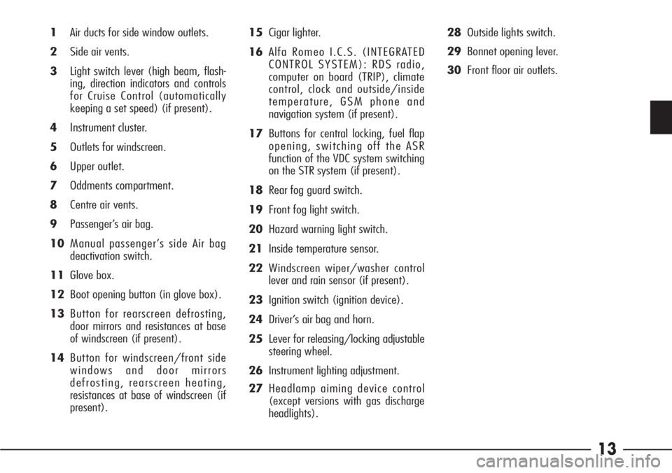
1Air ducts for side window outlets.
2Side air vents.
3Light switch lever (high beam, flash-
ing, direction indicators and controls
for Cruise Control (automatically
keeping a set speed) (if present).
4Instrument cluster.
5Outlets for windscreen.
6Upper outlet.
7Oddments compartment.
8Centre air vents.
9Passenger’s air bag.
10Manual passenger’s side Air bag
deactivation switch.
11Glove box.
12Boot opening button (in glove box).
13Button for rearscreen defrosting,
door mirrors and resistances at base
of windscreen (if present).
14Button for windscreen/front side
windows and door mirrors
defrosting, rearscreen heating,
resistances at base of windscreen (if
present).15Cigar lighter.
16Alfa Romeo I.C.S. (INTEGRATED
CONTROL SYSTEM): RDS radio,
computer on board (TRIP), climate
control, clock and outside/inside
temperature, GSM phone and
navigation system (if present).
17Buttons for central locking, fuel flap
opening, switching off the ASR
function of the VDC system switching
on the STR system (if present).
18Rear fog guard switch.
19Front fog light switch.
20Hazard warning light switch.
21Inside temperature sensor.
22Windscreen wiper/washer control
lever and rain sensor (if present).
23Ignition switch (ignition device).
24Driver’s air bag and horn.
25Lever for releasing/locking adjustable
steering wheel.
26Instrument lighting adjustment.
27Headlamp aiming device control
(except versions with gas discharge
headlights).28Outside lights switch.
29Bonnet opening lever.
30Front floor air outlets.
Page 29 of 272
28 DOORS
AUTOMATIC DOOR LOCKING
The automatic door locking function acti-
vates automatically when the car speed
exceeds 20 km/h.
This function can be deactivated and re-
activated by the following procedure, to
be carried out with the car at a standstill,
key at STOPand doors closed:
- turn the key to MAR
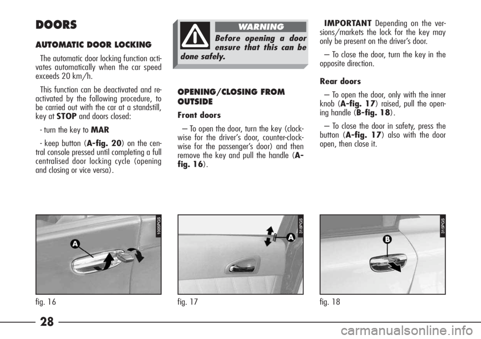
- keep button (A-fig. 20) on the cen-
tral console pressed until completing a full
centralised door locking cycle (opening
and closing or vice versa).IMPORTANTDepending on the ver-
sions/markets the lock for the key may
only be present on the driver’s door.
– To close the door, turn the key in the
opposite direction.
Rear doors
– To open the door, only with the inner
knob (A-fig. 17) raised, pull the open-
ing handle (B-fig. 18).
– To close the door in safety, press the
button (A-fig. 17) also with the door
open, then close it.
OPENING/CLOSING FROM
OUTSIDE
Front doors
– To open the door, turn the key (clock-
wise for the driver’s door, counter-clock-
wise for the passenger’s door) and then
remove the key and pull the handle (A-
fig. 16).
Before opening a door
ensure that this can be
done safely.
WARNING
315PGS1005PGS
fig. 16 fig. 18
318PGS
fig. 17
Page 71 of 272
70
IMPORTANT Depending on the trim
levels, the dial of the instruments may be
either light grey or black, with green or
red light.
A - Speedometer
IMPORTANT The rev counter may
have different clock values depending on
the different versions of the car.B - Mileage recorder with double
meter display (total and trip)
The display shows:
– the mileage on the first line (6 fig-
ures)
– the trip meter (4 figures) on the sec-
ond line.
Reset the partial km. and hold the push-
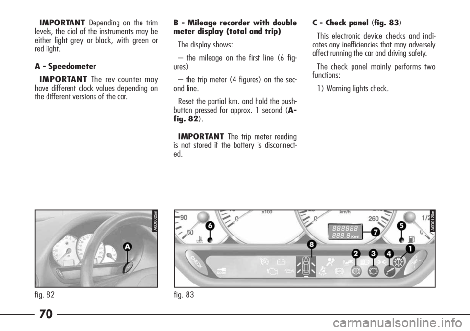
button pressed for approx. 1 second (A-
fig. 82).
IMPORTANT The trip meter reading
is not stored if the battery is disconnect-
ed.C - Check panel (fig. 83)
This electronic device checks and indi-
cates any inefficiencies that may adversely
affect running the car and driving safety.
The check panel mainly performs two
functions:
1) Warning lights check.
A0D0025mA0D0120m
fig. 82 fig. 83
Page 106 of 272
105
– Using the special key (B-fig. 133)
provided in the tool bag rotate bushing
(C-fig. 133) of the motor to move the
sunroof.
IMPORTANT When the operation has
been ended the key should be turned half
a turn in the opposite direction until a
click is heard before it is removed.LUGGAGE
COMPARTMENT
The boot lid can be opened from outside
the vehicle and from inside the vehicle.
IMPORTANT If the boot is not prop-
erly shut, the corresponding warning light
on the check panel will come on.
OPENING FROM OUTSIDE
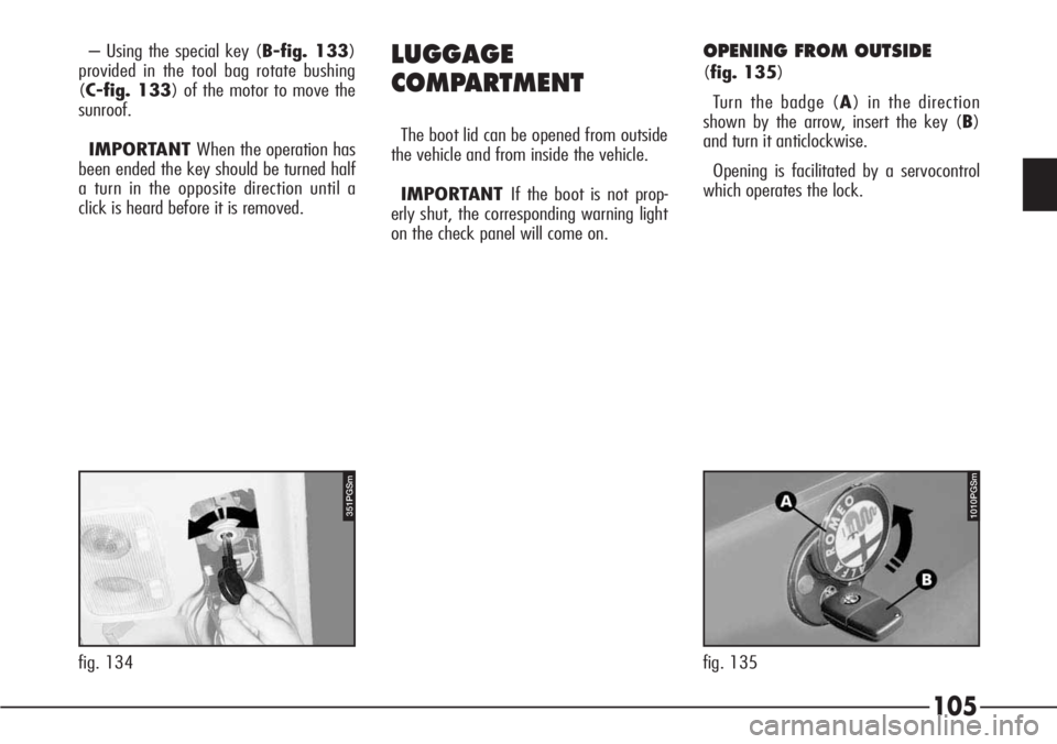
(fig. 135)
Turn the badge (A) in the direction
shown by the arrow, insert the key (B)
and turn it anticlockwise.
Opening is facilitated by a servocontrol
which operates the lock.
351PGSm
fig. 134
1010PGSm
fig. 135
Page 166 of 272
165
GENERAL INSTRUCTIONS
– When a light is not working check
that the corresponding fuse is intact be-
fore replacing the bulb.
– For the location of fuses, refer to the
paragraph “In the event of a burnt fuse”
in this chapter.
– Before changing a bulb check the
contacts for oxidation.
– Burnt bulbs must be replaced with
others of the same type and power.
– Always check the height of the head-
light beam after changing a bulb to en-
sure they are safe.
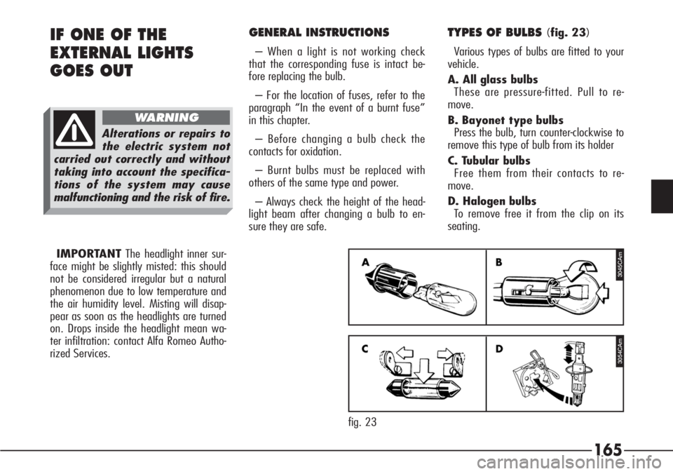
TYPES OF BULBS (fig. 23)
Various types of bulbs are fitted to your
vehicle.
A. All glass bulbs
These are pressure-fitted. Pull to re-
move.
B. Bayonet type bulbs
Press the bulb, turn counter-clockwise to
remove this type of bulb from its holder
C. Tubular bulbs
Free them from their contacts to re-
move.
D. Halogen bulbs
To remove free it from the clip on its
seating.IF ONE OF THE
EXTERNAL LIGHTS
GOES OUT
Alterations or repairs to
the electric system not
carried out correctly and without
taking into account the specifica-
tions of the system may cause
malfunctioning and the risk of fire.
WARNING
3045CAm
3054CAm
fig. 23 IMPORTANTThe headlight inner sur-
face might be slightly misted: this should
not be considered irregular but a natural
phenomenon due to low temperature and
the air humidity level. Misting will disap-
pear as soon as the headlights are turned
on. Drops inside the headlight mean wa-
ter infiltration: contact Alfa Romeo Autho-
rized Services.
Page 170 of 272

169
High beam headlamp signaller
To replace the bulb (Type D – H1,
55W):
– Remove the engine compartment cov-
er after turning the fastening pins.
– Turn counter-clockwise and remove
the direction indicator bulb holder (A-
fig. 29), without disconnecting the con-
nector to widen the working space.
– Remove the rubber cap (B) by
pulling the tab (C).– Disconnect the snap-fitted connector
(D- fig. 30) and release clip (E).
– Remove the bulb (F- fig. 31).– Fit new bulb in the headlight reflector
making the notches coincide with the cor-
responding grooves.
– Lock the bulb with the clip.
– Fit the connector to the bulb.
– Fit the rubber cap.
– Fit the direction indicator bulb holder
and lock it by turning it clockwise.
– Refit the engine compartment cover
and secure it by turning the fastening
pins.
A0D0059m
fig. 29
A0D0060m
fig. 30
A0D0061m
fig. 31
Page 171 of 272

170
Front sidelights
To replace the bulb (Type B – H6W,
6W):
– Remove the engine compartment cov-
er after turning the fastening pins.
– Turn counter-clockwise and remove
the direction indicator bulb holder (A-
fig. 32) without disconnecting the con-
nector to widen the working space.
– Remove the rubber cap (B) by
pulling the tab (C).– Press the two retaining tabs and re-
move the bulb holder (D- fig. 33).
– Remove the bulb (E- fig. 34) from
the bulb holder, pushing it slightly and
turning it counter-clockwise.– Fit the new bulb into the bulb holder,
pushing it slightly and turning it clock-
wise.
– Push the bulb holder down in its seat.
– Fit the rubber cap.
– Fit the direction indicator bulb holder
and lock it by turning it clockwise.
– Refit the engine compartment cover
and secure it by turning the fastening
pins.
A0D0059m
fig. 32
A0D0062m
fig. 33
A0D0063m
fig. 34
Page 172 of 272

171
Front direction indicators
To replace the bulb (Type B – PY21W,
21W, coloured):
– Remove the engine compartment cov-
er after turning the fastening pins.
– Turn counter-clockwise and remove
the bulb holder (A- fig. 35) without
disconnecting the connector.
– Remove the bulb (B- fig. 36) from
the bulb holder, pushing it slightly and
turning it counter-clockwise.– Fit the new bulb into the bulb holder,
pushing it slightly and turning it clock-
wise.
– Fit the bulb holder and lock it by turn-
ing it clockwise.
– Refit the engine compartment cover
and secure it by turning the fastening
pins.FRONT LIGHT UNITS –
HALOGEN BULB HEADLIGHTS
(optional for versions/markets where
applicable)
The front light units with halogen bulb
headlights contain low beam, high beam,
sidelight and direction indicator bulbs.
The bulbs are arranged inside the light
unit as follows (fig. 37-38):
A.Direction indicator
B.High beam headlight and sidelight
C.Low beam headlight.
A0D0070m
fig. 35
A0D0071m
fig. 36
A0D0054m
fig. 37
Page 174 of 272

173
High beam headlights
To replace the bulb (Type D – H7,
55W):
– Remove the engine compartment cov-
er after turning the fastening pins.
– Turn counter-clockwise and remove
the direction indicator bulb holder (A-
fig. 42) without disconnecting the con-
nector to widen the working space.
– Remove the rubber cap (B) by
pulling the tab (C).– Disconnect the snap-fitted connector
(D- fig. 43) and release the clip (E).
– Remove the bulb (F- fig. 44).– Fit the new bulb in the headlight re-
flector making the notches coincide with
the corresponding grooves.
– Lock the bulb with the clip.
– Fit the connector to the bulb.
– Fit the rubber cap.
– Fit the direction indicator bulb holder
and lock it by turning it clockwise.
– Refit the engine compartment cover
and secure it by turning the fastening
pins.
A0D0075m
fig. 42
A0D0076m
fig. 43
A0D0077m
fig. 44
Page 175 of 272

174
Front sidelights
To replace the bulb (Type B – H6W,
6W):
– Remove the engine compartment cov-
er after turning the fastening pins.
– Turn counter-clockwise and remove
the direction indicator bulb holder (A-
fig. 45) without disconnecting the con-
nector to widen the working space.
– Remove the rubber cap (B) by pulling
the tab (C).– Press the two retaining tabs and re-
move the bulb holder (D- fig. 46).
– Remove the bulb (E- fig. 47) from
the bulb holder, pushing it slightly and
turning it counter-clockwise.– Fit the new bulb into the bulb holder,
pushing it slightly and turning it clock-
wise.
– Push the bulb holder down in its seat.
– Fit the rubber cap.
– Fit the direction indicator bulb holder
and lock it by turning it clockwise.
– Refit the engine compartment cover
and secure it by turning the fastening
pins.
A0D0075m
fig. 45
A0D0078m
fig. 46
A0D0079m
fig. 47