fuse box location Alfa Romeo 166 2006 Owner handbook (in English)
[x] Cancel search | Manufacturer: ALFA ROMEO, Model Year: 2006, Model line: 166, Model: Alfa Romeo 166 2006Pages: 272, PDF Size: 4.17 MB
Page 192 of 272

191
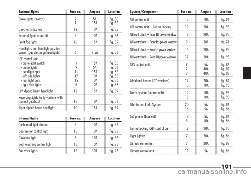
System/Component Fuse no. Ampere Location
ABI control unit 13 10A fig. 86
ABI control unit – Central locking 19 20A fig. 93
ABI control unit – Front LH power window 18 20Afig. 93
ABI control unit – Front RH power window 3 20A fig. 93
ABI control unit – Rear LH power window 14 20Afig. 93
ABI control unit – Rear RH power window 17 20Afig. 93
ABS control unit 9 5A fig. 86
7 40A fig. 89
3 40A fig. 89
Additional heater (JTD versions) 17 20A fig. 89
13 10A fig. 93
Alarm system (control unit) 12 10A fig. 93
15 10A fig. 93
Alfa Romeo Code System 20 5A fig. 86
16 5A fig. 86
Cell phone (handset) 18 5A fig. 86
5 10A fig. 86
Central locking (ABI control unit) 19 20A fig. 93
Cigar lighter 7 20A fig. 86
Climate control fan 2 30A fig. 89
Climate control unit 19 5A fig. 86
External lights Fuse no. Ampere Location
Brake lights (switch) 9 5A fig. 861 15A fig. 86
Direction indicators 12 10A fig. 93
External lights (control) 5 10A fig. 86
Front fog lights 16 15A fig. 89
Headlights and headlight position
sensor (gas discharge headlights) 6 7.5A fig. 86
IGE control unit:
- brake light switch 1 15A fig. 86
- brake lights 9 5A fig. 86
- headlight spot 11 15A fig. 86
- left side lights 17 10A fig. 86
- rear light units 15 10A fig. 86
- right side lights 8 10A fig. 86
Left dipped beam headlight 12 15A fig. 89
Reversing lights (only versions with
manual gearbox) 13 10A fig. 86
Right dipped beam headlight 10 15A fig. 89
Internal lights Fuse no. Ampere Location
Dashboard light dimmer 5 10A fig. 86
Door mirror control light 15 10A fig. 93
Glovebox light 5 10A fig. 86
Seat warming control light 15 10A fig. 93
Sun visor lights 15 10A fig. 93
Page 193 of 272

192
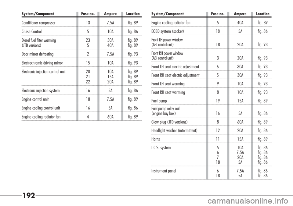
System/Component Fuse no. Ampere Location
Conditioner compressor 13 7.5A fig. 89
Cruise Control 5 10A fig. 86
Diesel fuel filter warming 23 30Afig. 89
(JTD versions) 5 40Afig. 89
Door mirror defrosting 2 7.5A fig. 93
Electrochromic driving mirror 15 10A fig. 93
Electronic injection control unit 20 10A fig. 89
21 15A fig. 89
22 20A fig. 89
Electronic injection system 16 5A fig. 86
Engine control unit 18 7.5A fig. 89
Engine cooling control unit 16 5A fig. 86
Engine cooling radiator fan 4 60A fig. 89
System/Component Fuse no. Ampere Location
Engine cooling radiator fan 5 40A fig. 89
EOBD system (socket) 18 5A fig. 86
Front LH power window
(ABI control unit) 18 20Afig. 93
Front RH power window
(ABI control unit) 3 20Afig. 93
Front LH seat electric adjustment 6 30A fig. 93
Front RH seat electric adjustment 5 30A fig. 93
Front LH seat warming 9 10A fig. 93
Front RH seat warming 8 10A fig. 93
Fuel pump 19 15A fig. 89
Fuel pump relay coil
(engine bay box) 16 5Afig. 86
Glow plug (JTD versions) 8 60A fig. 89
Headlight washer (intermittent) 12 20A fig. 86
Horns 11 15A fig. 89
I.C.S. system 5 10A fig. 86
6 7.5A fig. 86
7 20A fig. 86
18 5A fig. 86
Instrument panel 6 7.5A fig. 86
18 5A fig. 86
Page 194 of 272

193
System/Component Fuse no. Ampere Location
Rearscreen heating 1 30A fig. 93
Relay coil T21, T22, T23 (boot box) 3 5A fig. 86
Relay coil T24 (boot box) 5 10A fig. 86
Remote control receiver 15 10A fig. 93
Sound amplifier 20 25A fig. 93
Sound system 4 15A fig. 86
Sound system controls on steering wheel 5 10Afig. 86
Starter motor 1 30A fig. 89
Trailer presetting 12 10A fig. 93
Windscreen heating 7 15A fig. 93
Windscreen wiper 14 25A fig. 86
System/Component Fuse no. Ampere Location
Navigator 18 5A fig. 86
Parking sensors (control unit) 15 10A fig. 93
Power windows (driver's control
LOCK warning light) 15 10A fig. 93
Powered sunroof 10 20A fig. 93
Presetting 4 – fig. 93
11 – fig. 93
Rain sensor 15 10A fig. 93
Rear current socket 16 20A fig. 93
Rear LH power window (ABI control unit) 14 20Afig. 93
Rear RH power window (ABI control unit) 17 20Afig. 93