Alfa Romeo 166 2008 Owner handbook (in English)
Manufacturer: ALFA ROMEO, Model Year: 2008, Model line: 166, Model: Alfa Romeo 166 2008Pages: 272, PDF Size: 4.17 MB
Page 181 of 272

180
ADDITIONAL STOP LIGHT
(3rdSTOP)
To replace the bulbs (Type A, 2.3 W):
– Remove the rubber caps (A-
fig. 63).– Slacken the two screws fastening the
light unit (B-fig. 64) and remove it re-
leasing the two catches (C).
– Disconnect the connector (D-
fig. 64) of the light unit.
– Slacken the two screws (E-fig. 65)
and separate the light unit from the cov-
er.– Slacken the four screws (F-fig. 66)
fastening the transparent cover.
– Remove the transparent cover (G-
fig. 67) and replace the bulb concerned
– Refit the transparent cover locking it
with the screws (F-fig. 66).
– Refit the cover on the light unit and
fasten it with the screws (E-fig. 65).
– Connect the connector (D-fig. 64).
– Re-position the unit correctly firstly in-
serting the two catches (C-fig. 64) and
then tightening the fastening screws.
– Refit the protective caps (A-
fig. 63).
485PGSm488PGSm
fig. 64 fig. 66 fig. 67
484PGSm
fig. 63
486PGSm
fig. 65
487PGSm
Page 182 of 272

181
IF ONE OF THE
INTERNAL LIGHTS
GOES OUT
FRONT ROOF LIGHT
To replace the bulbs (Type B, 10W Halo-
gen):
– Remove the roof light (A-fig. 68)
levering in the point illustrated.
– Remove the screen (B-fig. 69)
firstly releasing it from the catch (C) on
the right and then from the two stoppers
on the left.
– Remove and replace the bulb con-
cerned (D-fig. 70) (tubular with bayo-
net coupling), pushing gently and turning
counter-clockwise.When refitting the roof
light ensure that the
electrical wiring is cor-
rectly arranged and does not in-
terfere with the edges of the
light or retaining clips.
– Refit the screen (B-fig. 69), firstly
inserting the left side under the two stop-
pers then on the right side until the catch
clicks. (C-fig. 69).
– Refit the roof light firstly inserting the
front part, then pressing in the rear part
to fit it in place.
631PGSm632PGSm
fig. 69 fig. 68 fig. 70
607PGSm
Page 183 of 272

182
– Remove and replace the bulb (B-fig.
72) (tubular with bayonet coupling)
pushing gently and turning counter-clock-
wise.
– Refit the roof light firstly hooking the
catch (C-fig. 72) and pressing on the
other side until the catch clicks into place
(D-fig. 72).COURTESY LIGHTS
To replace the bulb (Type C, 5W):
– Remove the light (A-fig. 73) lever-
ing in the point illustrated.
REAR ROOF LIGHTS
To replace the bulbs (Type B, 5W):
– Remove the roof light (A-fig. 71)
levering in the point illustrated.
fig. 73fig. 71
492PGSm494PGSm493PGSm
fig. 72
Page 184 of 272

183
GLOVEBOX LIGHT
To replace the bulb (Type A, 5W):
– Remove the light pushing with a
screwdriver on the tab (A-fig. 76)
– Press the sides of the bulb screen (B-
fig. 77) in correspondence with the two
fastening pins and turn it. – Remove the screen (B-fig. 74) re-
leasing it from the catches (C-fig. 74)
– Remove the bulb (D-fig. 75)
pulling outwards and releasing from the
side contacts.
– Insert the new bulb making sure that
it is positioned correctly and locked be-
tween the contacts.
– Refit the screen (B-fig. 74) insert-
ing it correctly between the catches (C-
fig. 74).– Refit the light unit firstly inserting
from the side (E-fig. 75) and then
pressing on the other side until the catch
clicks into place (F-fig. 75).
P4C00057495PGSm
fig. 74
496PGSm
fig. 75
630PGSm
fig. 76
Page 185 of 272

184
– Change the bulb (C-fig. 77) which
is pressure-fitted.
– Re-position the screen inserting the
two fastening pins.
– Re-install the light inserting it in the
correct position firstly on one side (D-
fig. 76) and then pushing on the other
until the tab clicks.DOOR LIGHTS
To replace the bulb (Type A, 5W):
– Remove the light pushing with a
screwdriver on the tab (A-fig. 78).
– Press on the side of the screen (B-
fig. 79) in correspondence with the two
fastening pins and turn it.– Change the bulb (C-fig. 79) which
is pressure-fitted.
– Re-position the screen inserting the
two fastening pins.
– Re-install the light inserting it firstly
on one side (D-fig. 78) and then push-
ing on the other until the tab clicks.
628PGS
fig. 79
629PGSm
fig. 77
502PGSm627PGSm
fig. 78
Page 186 of 272

185
– Fit the new bulb locking it between
the two contacts.
– Lower the protection cover.
– Refit the light by locking it in its seat.LUGGAGE COMPARTMENT
LIGHT
To replace the bulb (Type C, 10W):
– Remove the light levering on point
(A- fig. 80) with a screwdriver.– Lift the protection cover (B- fig.
81).
– Remove the snap-fitted bulb (C- fig.
82).
A0D0085m
fig. 80
A0D0086m
fig. 81
A0D0087m
fig. 82
Page 187 of 272

186 IN THE EVENT OF
A BURNT FUSE
OR RELAY
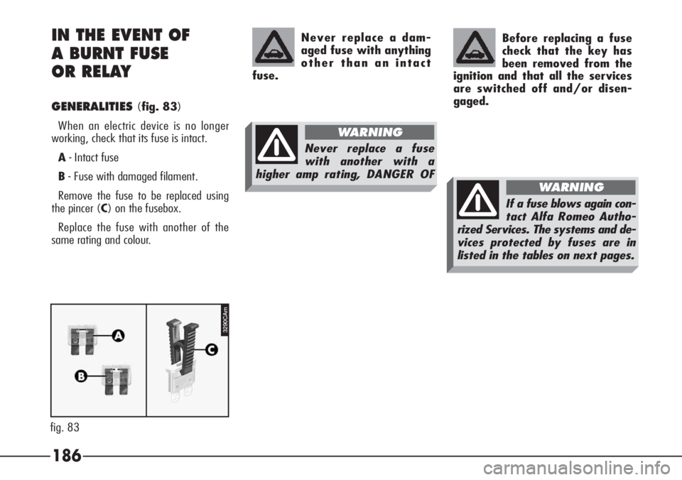
GENERALITIES(fig. 83)
When an electric device is no longer
working, check that its fuse is intact.
A- Intact fuse
B- Fuse with damaged filament.
Remove the fuse to be replaced using
the pincer (C) on the fusebox.
Replace the fuse with another of the
same rating and colour.Before replacing a fuse
check that the key has
been removed from the
ignition and that all the services
are switched off and/or disen-
gaged.
Never replace a dam-
aged fuse with anything
other than an intact
fuse.
Never replace a fuse
with another with a
higher amp rating, DANGER OF
WARNING
3290CAm
fig. 83
If a fuse blows again con-
tact Alfa Romeo Autho-
rized Services. The systems and de-
vices protected by fuses are in
listed in the tables on next pages.
WARNING
Page 188 of 272

187
FUSES AND RELAYS IN THE
CONTROL UNIT
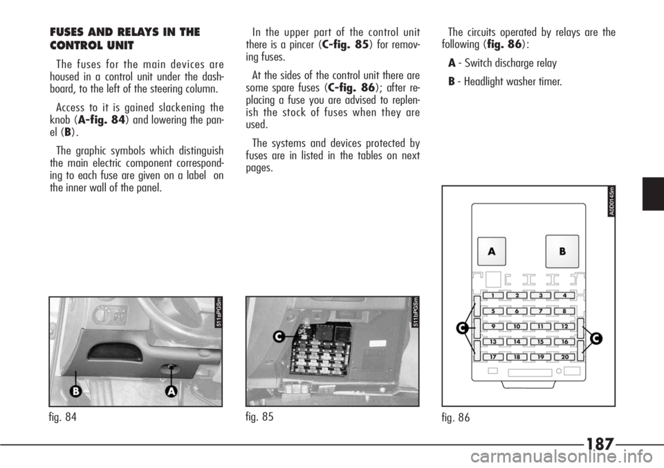
The fuses for the main devices are
housed in a control unit under the dash-
board, to the left of the steering column.
Access to it is gained slackening the
knob (A-fig. 84) and lowering the pan-
el (B).
The graphic symbols which distinguish
the main electric component correspond-
ing to each fuse are given on a label on
the inner wall of the panel.In the upper part of the control unit
there is a pincer (C-fig. 85) for remov-
ing fuses.
At the sides of the control unit there are
some spare fuses (C-fig. 86); after re-
placing a fuse you are advised to replen-
ish the stock of fuses when they are
used.
The systems and devices protected by
fuses are in listed in the tables on next
pages.The circuits operated by relays are the
following (fig. 86):
A- Switch discharge relay
B- Headlight washer timer.
511bPGSm
fig. 85
511aPGSm
fig. 84
A0D0145m
fig. 86
Page 189 of 272

188
FUSES AND RELAYS IN
ENGINE BAY
The fuses and relays in the engine bay
are housed:
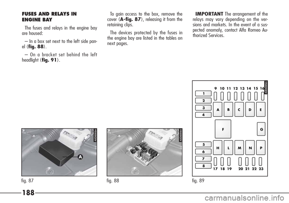
– In a box set next to the left side pan-
el (fig. 88).
– On a bracket set behind the left
headlight (fig. 91).To gain access to the box, remove the
cover (A-fig. 87), releasing it from the
retaining clips.
The devices protected by the fuses in
the engine bay are listed in the tables on
next pages.IMPORTANTThe arrangement of the
relays may vary depending on the ver-
sions and markets. In the event of a sus-
pected anomaly, contact Alfa Romeo Au-
thorized Services.
A0D0093m
fig. 87
A0D0094m
fig. 88 fig. 89
A0D0095m
Page 190 of 272

189
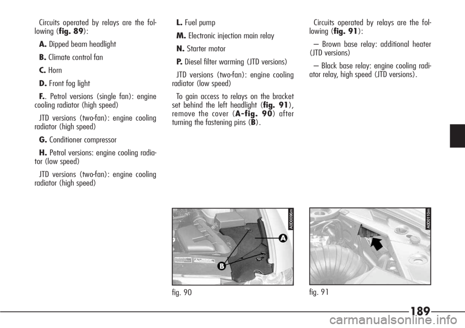
Circuits operated by relays are the fol-
lowing (fig. 89):
A.Dipped beam headlight
B.Climate control fan
C.Horn
D.Front fog light
F.. Petrol versions (single fan): engine
cooling radiator (high speed)
JTD versions (two-fan): engine cooling
radiator (high speed)
G.Conditioner compressor
H.Petrol versions: engine cooling radia-
tor (low speed)
JTD versions (two-fan): engine cooling
radiator (high speed)L.Fuel pump
M.Electronic injection main relay
N.Starter motor
P.Diesel filter warming (JTD versions)
JTD versions (two-fan): engine cooling
radiator (low speed)
To gain access to relays on the bracket
set behind the left headlight (fig. 91),
remove the cover (A-fig. 90) after
turning the fastening pins (B).Circuits operated by relays are the fol-
lowing (fig. 91):
– Brown base relay: additional heater
(JTD versions)
– Black base relay: engine cooling radi-
ator relay, high speed (JTD versions).
A0D0096m
fig. 90
A0D0110m
fig. 91