dashboard Alfa Romeo 4C 2014 Owner handbook (in English)
[x] Cancel search | Manufacturer: ALFA ROMEO, Model Year: 2014, Model line: 4C, Model: Alfa Romeo 4C 2014Pages: 190, PDF Size: 7.87 MB
Page 10 of 190
.
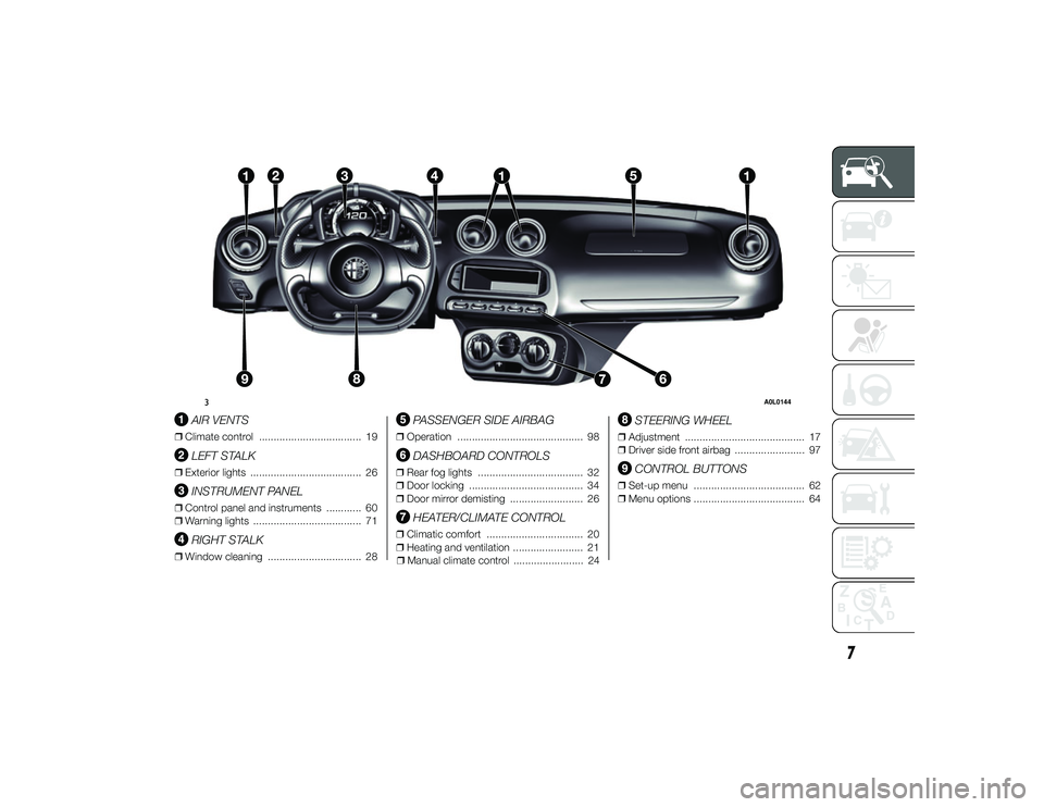
AIR VENTS
ŌØÆClimate control ................................... 19
LEFT STALK
ŌØÆExterior lights ...................................... 26
INSTRUMENT PANEL
ŌØÆControl panel and instruments ............ 60
ŌØÆ Warning lights ..................................... 71
RIGHT STALK
ŌØÆWindow cleaning ................................ 28
PASSENGER SIDE AIRBAG
ŌØÆOperation ........................................... 98
DASHBOARD CONTROLS
ŌØÆRear fog lights .................................... 32
ŌØÆ Door locking ....................................... 34
ŌØÆ Door mirror demisting ......................... 26
HEATER/CLIMATE CONTROL
ŌØÆClimatic comfort ................................. 20
ŌØÆ Heating and ventilation ........................ 21
ŌØÆ Manual climate control ........................ 24
STEERING WHEEL
ŌØÆAdjustment ......................................... 17
ŌØÆ Driver side front airbag ........................ 97
CONTROL BUTTONS
ŌØÆSet-up menu ...................................... 62
ŌØÆ Menu options ...................................... 64
3
A0L0144
7
24-9-2013 11:49 Pagina 7
Page 15 of 190
If one or more door are open, the doors
will not be locked. This is indicated by
a rapid flashing of the direction
indicators (for versions/markets, where
provided). The doors will be locked if
the tailgate is open however.
When a speed of more than 20 km/h is
reached, the doors will be locked
automatically if this specific function
was set.
When the doors are locked from
outside the car (using the remote
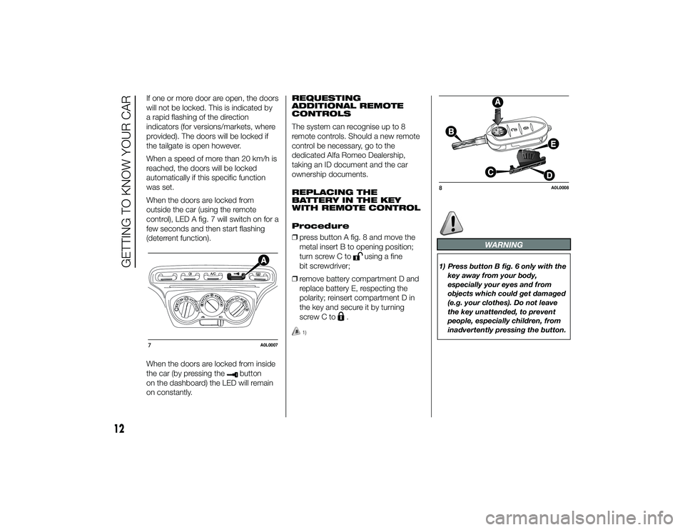
control), LED A fig. 7 will switch on for a
few seconds and then start flashing
(deterrent function).
When the doors are locked from inside
the car (by pressing the
button
on the dashboard) the LED will remain
on constantly. REQUESTING
ADDITIONAL REMOTE
CONTROLS
The system can recognise up to 8
remote controls. Should a new remote
control be necessary, go to the
dedicated Alfa Romeo Dealership,
taking an ID document and the car
ownership documents.
REPLACING THE
BATTERY IN THE KEY
WITH REMOTE CONTROL
Procedure
ŌØÆ
press button A fig. 8 and move the
metal insert B to opening position;
turn screw C to
using a fine
bit screwdriver;
ŌØÆ remove battery compartment D and
replace battery E, respecting the
polarity; reinsert compartment D in
the key and secure it by turning
screw C to
.
1)
WARNING
1) Press button B fig. 6 only with the
key away from your body,
especially your eyes and from
objects which could get damaged
(e.g. your clothes). Do not leave
the key unattended, to prevent
people, especially children, from
inadvertently pressing the button.
7
A0L0007
8
A0L0008
12
GETTING TO KNOW YOUR CAR
24-9-2013 11:49 Pagina 12
Page 16 of 190
IMPORTANT
1) Used batteries may be harmful tothe environment if not disposed of
correctly. They must be disposed
of as specified by law in the
special containers or taken to the
dedicated Alfa Romeo Dealership,
which will take care of their
disposal.
ALARM(for versions/markets, where provided)
Operation
The alarm activates in the following
cases:
ŌØÆwrongful opening of one of the doors
or the tailgate (perimeter protection);
ŌØÆ wrongful operation of the ignition
switch (key turned to MAR-ON);
ŌØÆ cutting of the battery leads;
ŌØÆ movement inside the passenger
compartment (volumetric protection);
ŌØÆ anomalous lifting/tilting of the car.
Operation of the alarm is indicated by
an acoustic and visual signal (flashing of
the direction indicators for several
seconds). The alarm activation modes
may vary according to the market.
There is a maximum number of
acoustic/visual cycles. When this is
reached the system returns to normal
operation.
IMPORTANT The engine locking
function is guaranteed by the Alfa
Romeo CODE, which is automatically
activated when the key is extracted
from the ignition switch.
IMPORTANT The alarm is adapted to
meet requirements in various countries. Activation
With the doors and tailgate closed and
the ignition key either turned to STOP
or removed, point the key with remote
control towards the car then press
and release the
button.
For versions/markets, where provided,
the system emits an acoustic signal
and activates door locking.
A self-diagnosis stage lasting
approximately 30 seconds precedes
the activation of the alarm: during this,
the LED flashes on the dashboard at
a frequency of about one flash per
second.
After the self-diagnosis stage, the LED
flashes at a lower frequency (one flash
every 3 seconds approx.).
If, after the alarm is switched on, a
second acoustic signal is emitted
and/or a visual signal via the LED on
the dashboard, wait about 4 seconds
and switch off the alarm by pressing the
button, check that the doors and
tailgate are closed correctly and then
reactivate the system by pressing
the
button.
If the alarm emits an acoustic signal
even when the doors and tailgate are
closed correctly, a system malfunction
has occurred: in this case, contact a
dedicated Alfa Romeo Dealership.
13
24-9-2013 11:49 Pagina 13
Page 17 of 190
Deactivation
Press the
button.
The following operations are performed
(for versions/markets, where provided):
ŌØÆ two brief flashes of the direction
indicators;
ŌØÆ unlocking of the doors.
IMPORTANT If the central door locking
system is released using the metal
insert of the key, the alarm is not
disabled.
IMPORTANT In the event of accidental
activation of the alarm, or in any case to
interrupt the acoustic and visual signal
cycle when activated, it is possible
to press thebutton or turn the
ignition key to MAR-ON for at least 5
seconds, after which the system will
deactivate.
Disabling
To completely disable the alarm (e.g.
during a lengthy period of car inactivity),
lock the car by turning the metal insert
of the key in the door lock.
IMPORTANT If the batteries of the key
with remote control run out or there is a
fault in the system, the alarm can be
switched off by inserting the key in the
ignition switch and turning it to
MAR-ON. Volumetric/anti-lift
protection
To ensure the correct operation of the
protection, completely close the side
windows.
To disable the volumetric protection,
turn the ignition key from STOP to
MAR-ON twice in a row, then activate
the alarm within 15 seconds, pressing
the
button on the remote control.
When the function is deactivated, this is
indicated by the LED on the dashboard
flashing for several seconds.
To disable the anti-lift protection as well,
the ignition key must be turned from
STOP to MAR-ON three times in a row,
followed by activating the alarm within
15 seconds, pressing the
button
on the remote control.
When the function is deactivated, this is
indicated by the LED on the dashboard
flashing for several seconds.
Any disabling of the volumetric/anti-lift
protection must be repeated each
time the instrument panel is switched
off.
IGNITION SWITCHOperation
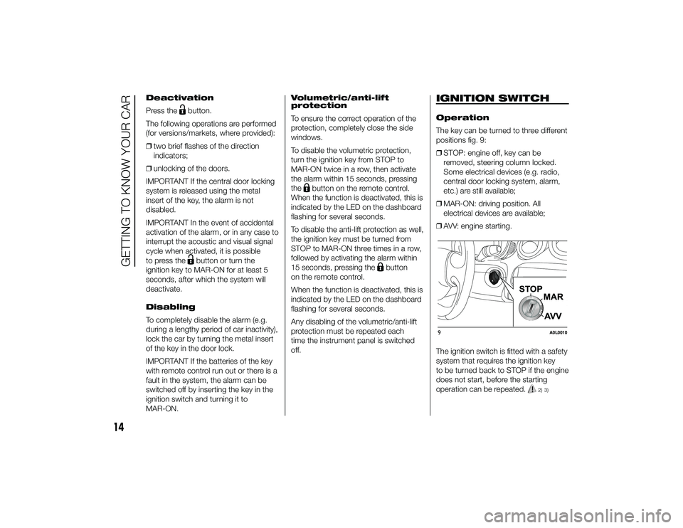
The key can be turned to three different
positions fig. 9:
ŌØÆ STOP: engine off, key can be
removed, steering column locked.
Some electrical devices (e.g. radio,
central door locking system, alarm,
etc.) are still available;
ŌØÆ MAR-ON: driving position. All
electrical devices are available;
ŌØÆ AVV: engine starting.
The ignition switch is fitted with a safety
system that requires the ignition key
to be turned back to STOP if the engine
does not start, before the starting
operation can be repeated.
2) 3)
9
A0L0010
14
GETTING TO KNOW YOUR CAR
24-9-2013 11:49 Pagina 14
Page 30 of 190

27
24-9-2013 11:49 Pagina 27
DAYTIME RUNNING
LIGHTS (DRL)
ŌĆ£Daytime Running LightsŌĆØ
With the ignition key at MAR-ON and
ring nut A fig. 22 turned to
, the
daytime running lights switch on. The
other lights and interior lighting stay off.
IMPORTANT The daytime running
lights are an alternative to the dipped
headlights for driving during the
daytime in countries where it is
compulsory to have lights on during the
day; where it is not compulsory, the
use of daytime running lights is
permitted.
IMPORTANT Daytime running lights
cannot be used in place of dipped
headlights when driving through tunnels
or at night. The use of daytime running
lights is governed by the Highway Code
of the country in which you are driving.
Comply with legal requirements.
SIDE LIGHTS/DIPPED
HEADLIGHTS
With the ignition key turned to
MAR-ON, turn ring nut A fig. 22 to
.
The daytime running lights are switched
off and the side lights and dipped
headlights are switched on. The
warning light switches on in the
instrument panel. PARKING LIGHTS
These lights can only be switched on
with ignition key at STOP or removed,
by moving ring nut A fig. 22 first to
position
and then to position
.
The
warning light switches on
in the instrument panel.
MAIN BEAM HEADLIGHTS
To activate the main beam headlights,
with ring nut A at
, pull the stalk
towards the steering wheel beyond the
end of travel position. The
warning
light switches on in the instrument
panel. When the stalk is pulled towards
the steering wheel again, beyond the
end of travel position, the main beam
headlights deactivate, the dipped beam
headlights reactivate and the warning
light
switches off.
FLASHING
To do this, pull the stalk towards the
steering wheel (unstable position)
regardless of the position of ring nut A.
Thewarning light switches on in the
instrument panel.
REAR FOG LIGHTS
For the activation and deactivation of
the rear fog lights, refer to the
"Controls" section.
22
A0L0020
EXTERIOR LIGHTS
IN BRIEF
The left stalk fig. 22 operates most of
the exterior lights. The exterior lights
can only be switched on when the
ignition key is at MAR-ON.
The instrument panel and the
dashboard and central tunnel
controls will light up together with the
exterior lights.
Page 36 of 190

After a collision, turn the ignition key to
STOP to prevent the battery from
running down.
To restore the correct operation of the
car, proceed as follows:
ŌØÆbring the left exterior light control
stalk to central position (neutral);
ŌØÆ turn the ignition key to the MAR-ON
position;
ŌØÆ activate the right direction indicator;
ŌØÆ deactivate the right direction
indicator;
ŌØÆ activate the left direction indicator;
ŌØÆ deactivate the left direction indicator;
ŌØÆ activate the right direction indicator;
ŌØÆ deactivate the right direction
indicator;
ŌØÆ activate the left direction indicator;
ŌØÆ deactivate the left direction indicator;
ŌØÆ turn the ignition key to the STOP
position;
ŌØÆ turn the ignition key to the MAR-ON
position.
WARNING
16) The use of hazard warning lights
is governed by the Highway Code
of the country you are driving in:
comply with legal requirements.
17) If, after an impact, you smell fuel or notice leaks from the fuel
system, do not reactivate the
system to avoid the risk of fire.
INTERIOR FITTINGSSTORAGE
COMPARTMENTS
Front
For versions/markets, where provided,
the car features a storage compartment
A fig. 29 on the dashboard.
Rear
This is located at the centre of the rear
partition, easily accessible from the 2
seats. To access it, press button A fig.
30 and release clasp B. There is a
lock in button A, permitting the storage
compartment to be locked using a
specific key.
On some versions, the storage
compartment is replaced with a mesh
pocket fig. 31.29
A0L0159
33
24-9-2013 11:49 Pagina 33
Page 37 of 190

ODDMENTS POCKET
(for versions/markets, where provided)
It is located under the dashboard, in
front of the passenger side seat, in the
point shown in fig. 32.POWER SOCKET
This is located on the central tunnel fig.
33.
IMPORTANT Do not connect devices
with power higher than 180 W to the
socket. Do not damage the socket by
using unsuitable adaptors.CIGAR LIGHTER
(for versions/markets, where provided)
Operation
This is located on the central tunnel.
Press button A fig. 34 to activate the
cigar lighter.
After a few seconds the button goes
back to its initial position and the cigar
lighter is ready for use.
18)
IMPORTANT Always check that the
cigar lighter has switched off.
IMPORTANT Do not connect devices
with power higher than 180 W to the
socket. Do not damage the socket by
using unsuitable adaptors.
30
A0L0156
31
A0L0157
32
A0L0166
33
A0L0030
34
A0L0031
34
GETTING TO KNOW YOUR CAR
24-9-2013 11:49 Pagina 34
Page 38 of 190

ASHTRAY
(for versions/markets, where provided)
This is a removable spring-loaded
plastic container B fig. 35 located on
the central tunnel.
19)
CUP HOLDER
(for versions/markets, where provided)
Cup holder C fig. 35 is located on
the central tunnel at the point illustrated
in the figure.
BACKREST POCKET
This is located at the back of the driver
side seat backrest fig. 36.SUN VISORS
These are located at the sides of the
interior rear view mirror. They may
be positioned at the front.
EXTINGUISHER
(for versions/markets, where provided)
This is located under the dashboard
in front of the passenger side seat, at
the point illustrated in fig. 37.
WARNING
18) The cigar lighter reaches high
temperatures Handle it carefully
and make sure that children donŌĆÖt
use it: risk of fire and/or burns.
19) Do not use the ashtray as a waste paper basket: it may
catch fire in contact with cigarette
stubs.
35
A0L0032
36
A0L0139
37
A0L0034
35
24-9-2013 11:49 Pagina 35
Page 39 of 190
DOORSCENTRAL DOOR
LOCKING/UNLOCKING
Locking doors from the
outside
With the doors closed, press thebutton on the key or turn the metal
insert (located inside the key) in the
door lock.
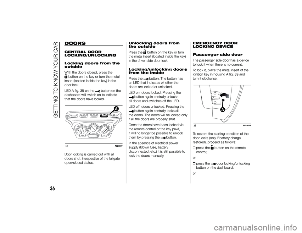
LED A fig. 38 on the
button on the
dashboard will switch on to indicate
that the doors have locked.
Door locking is carried out with all
doors shut, irrespective of the tailgate
open/closed status. Unlocking doors from
the outside
Press the
button on the key or turn
the metal insert (located inside the key)
in the driver side door lock.
Locking/unlocking doors
from the inside
Press thebutton. The button has
an LED that indicates whether the
doors are locked or unlocked.
LED on: doors locked. Pressing the
button again centrally unlocks
all doors and switches off the LED.
LED off: doors unlocked. Pressing thebutton again centrally locks all
the doors. The doors will be locked only
if all the doors are properly shut.
Once the doors have been locked via
the remote control or the key pawl,
it will no longer be possible to unlock
them by pressing the
button.
In the absence of electrical power
supply (blown fuse, battery
disconnected, etc.) it is still possible to
lock the doors manually. EMERGENCY DOOR
LOCKING DEVICE
Passenger side door
The passenger side door has a device
to lock it when there is no current.
To lock it, place the metal insert of the
ignition key in housing A fig. 39 and
turn it clockwise.
To restore the starting condition of the
door locks (only if battery charge
restored), proceed as follows:
ŌØÆ
press the
button on the remote
control;
or
ŌØÆ press thedoor locking/unlocking
button on the dashboard;
or
38
A0L0007
39
A0L0036
36
GETTING TO KNOW YOUR CAR
24-9-2013 11:49 Pagina 36
Page 40 of 190
ŌØÆintroduce the metal insert of the
ignition key in the front door pawl;
or
ŌØÆ pull the internal door handle.
Door opening/closing
mechanism initialisation
If the battery is disconnected or the
protection fuse blows, the door
opening/closing mechanism must be
initialised as follows:
ŌØÆ close all the doors;
ŌØÆ press the
button on the key or the
door locking/unlocking button on
the dashboard;
ŌØÆ press the
button on the key or the
door locking/unlocking button on
the dashboard.
ELECTRIC WINDOWS
IN BRIEF
These operate when the ignition key
is turned to MAR-ON and for about
three minutes after the ignition key is
turned to STOP or removed unless
one of the doors is opened.
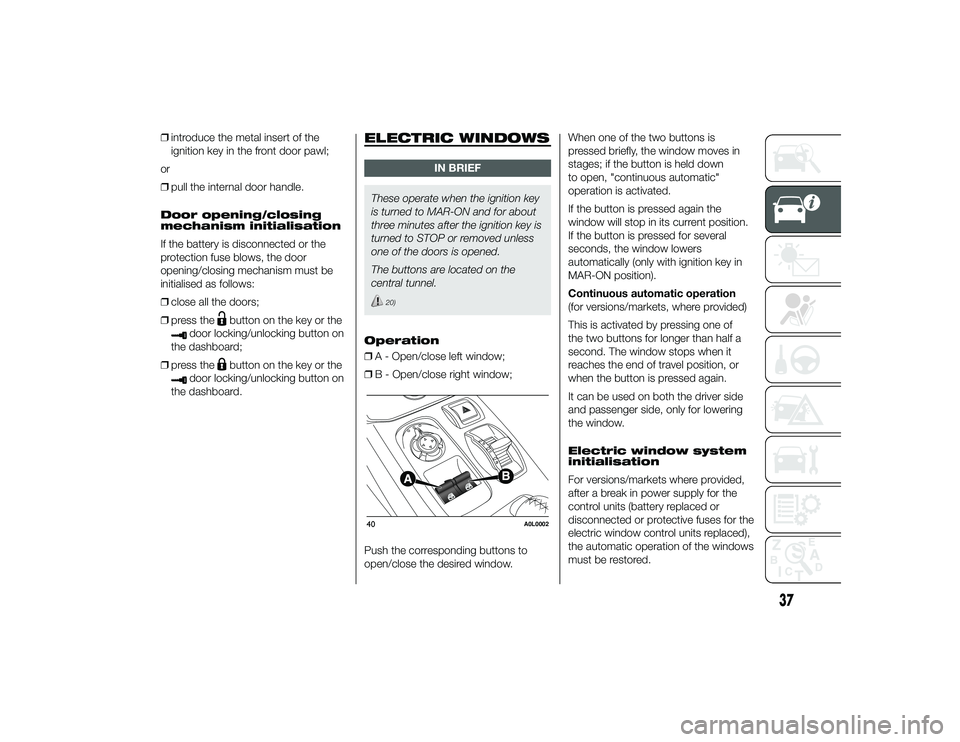
The buttons are located on the
central tunnel.
20)
Operation
ŌØÆ A - Open/close left window;
ŌØÆ B - Open/close right window;
Push the corresponding buttons to
open/close the desired window. When one of the two buttons is
pressed briefly, the window moves in
stages; if the button is held down
to open, "continuous automatic"
operation is activated.
If the button is pressed again the
window will stop in its current position.
If the button is pressed for several
seconds, the window lowers
automatically (only with ignition key in
MAR-ON position).
Continuous automatic operation
(for versions/markets, where provided)
This is activated by pressing one of
the two buttons for longer than half a
second. The window stops when it
reaches the end of travel position, or
when the button is pressed again.
It can be used on both the driver side
and passenger side, only for lowering
the window.
Electric window system
initialisation
For versions/markets where provided,
after a break in power supply for the
control units (battery replaced or
disconnected or protective fuses for the
electric window control units replaced),
the automatic operation of the windows
must be restored.40
A0L0002
37
24-9-2013 11:49 Pagina 37