boot Alfa Romeo Brera/Spider 2007 Owner handbook (in English)
[x] Cancel search | Manufacturer: ALFA ROMEO, Model Year: 2007, Model line: Brera/Spider, Model: Alfa Romeo Brera/Spider 2007Pages: 271, PDF Size: 6.04 MB
Page 8 of 271
6
SAFETY
DEVICES
WARNING
LIGHTS AND
MESSAGES
IN AN
EMERGENCY
CAR
MAINTENANCE
TECHNICAL
SPECIFICATIONS
INDEX
DASHBOARD
AND
CONTROLS
CORRECT USE
OF THE CAR
D D D D
A A A A
S S S S
H H H H
B B B B
O O O O
A A A A
R R R R
D D D D
A A A A
N N N N
D D D D
C C C C
O O O O
N N N N
T T T T
R R R R
O O O O
L L L L
S S S S
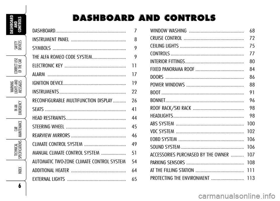
WINDOW WASHING .......................................... 68
CRUISE CONTROL .............................................. 72
CEILING LIGHTS ................................................. 75
CONTROLS ........................................................ 77
INTERIOR FITTINGS............................................. 80
FIXED PANORAMA ROOF ..................................... 84
DOORS ............................................................ 86
POWER WINDOWS ............................................ 88
BOOT ............................................................... 91
BONNET............................................................ 96
ROOF RACK/SKI RACK ....................................... 98
HEADLIGHTS...................................................... 98
ABS SYSTEM .................................................... 100
VDC SYSTEM .................................................... 102
EOBD SYSTEM .................................................. 106
SOUND SYSTEM ................................................ 106
ACCESSORIES PURCHASED BY THE OWNER .......... 107
PARKING SENSORS ............................................ 108
AT THE FILLING STATION ..................................... 111
PROTECTING THE ENVIRONMENT ......................... 113 DASHBOARD...................................................... 7
INSTRUMENT PANEL .......................................... 8
SYMBOLS ........................................................ 9
THE ALFA ROMEO CODE SYSTEM.......................... 9
ELECTRONIC KEY ............................................... 11
ALARM ............................................................ 17
IGNITION DEVICE................................................ 19
INSTRUMENTS ................................................... 22
RECONFIGURABLE MULTIFUNCTION DISPLAY .......... 26
SEATS .............................................................. 41
HEAD RESTRAINTS.............................................. 44
STEERING WHEEL .............................................. 45
REARVIEW MIRRORS .......................................... 46
CLIMATE CONTROL SYSTEM ................................ 49
MANUAL CLIMATE CONTROL SYSTEM ................... 51
AUTOMATIC TWO-ZONE CLIMATE CONTROL SYSTEM 54
ADDITIONAL HEATER .......................................... 64
EXTERNAL LIGHTS ............................................. 65
Page 13 of 271
11
SAFETY
DEVICES
WARNING
LIGHTS AND
MESSAGES
IN AN
EMERGENCY
CAR
MAINTENANCE
TECHNICAL
SPECIFICATIONS
INDEX
DASHBOARD
AND
CONTROLS
CORRECT USE
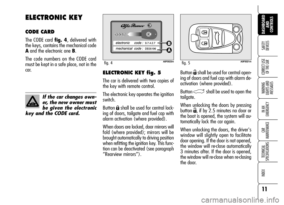
OF THE CARButton Ëshall be used for central open-
ing of doors and fuel cap with alarm de-
activation (where provided).
Button
`shall be used to open the
tailgate.
When unlocking the doors by pressing
button
Ë, if by 2.5 minutes no door or
the boot is opened, the system will au-
tomatically lock the car again.
When unlocking the doors, the driver's
window will slightly open to facilitate
door opening. If the door is not opened,
the window will re-close automatically
3 minutes after. If the door is opened,
the window will re-close when re-closing
the door.
ELECTRONIC KEY fig. 5
The car is delivered with two copies of
the key with remote control.
The electronic key operates the ignition
switch.
Button
Áshall be used for central lock-
ing of doors, tailgate and fuel cap with
alarm activation (where provided).
When doors are locked, door mirrors will
fold (where provided); mirrors will be
brought automatically to driving position
when refitting the ignition key. This func-
tion can be deactivated (see paragraph
“Rearview mirrors”).
ELECTRONIC KEY
CODE CARD
The CODE card fig. 4, delivered with
the keys, contains the mechanical code
Aand the electronic one B.
The code numbers on the CODE card
must be kept in a safe place, not in the
car.
A0F0023mfig. 4A0F0021mfig. 5
If the car changes own-
er, the new owner must
be given the electronic
key and the CODE card.
Page 19 of 271
17
SAFETY
DEVICES
WARNING
LIGHTS AND
MESSAGES
IN AN
EMERGENCY
CAR
MAINTENANCE
TECHNICAL
SPECIFICATIONS
INDEX
DASHBOARD
AND
CONTROLS
CORRECT USE
OF THE CAR
Depending on the markets, the trigger-
ing of the alarm will activate the siren
and the hazard warning lights (for about
26 seconds). The methods of operation
and the number of cycles may vary de-
pending on the versions/markets.
A maximum number of sound/sight cy-
cles is however envisaged. Once the
alarm cycle is over, the system will re-
store its normal operation.
IMPORTANTCentral door unlocking
by the emergency electronic key will not
deactivate the alarm, therefore with
alarm on the siren will activate when
opening one of the doors or the boot.
To deactivate the siren see paragraph
“How to deactivate the alarm”.
IMPORTANTThe engine immobiliser
function is guaranteed by the Alfa
Romeo CODE system, which is auto-
matically activated when the electronic
key is removed from the ignition device.
HOW TO ACTIVATE
THE ALARM
With the doors, bonnet and boot shut
and electronic key removed from igni-
tion switch, point the electronic key in
the direction of the car, then press and
release the button
Á.
With the exception of certain markets,
the system sounds a “beep” and the
doors are locked.
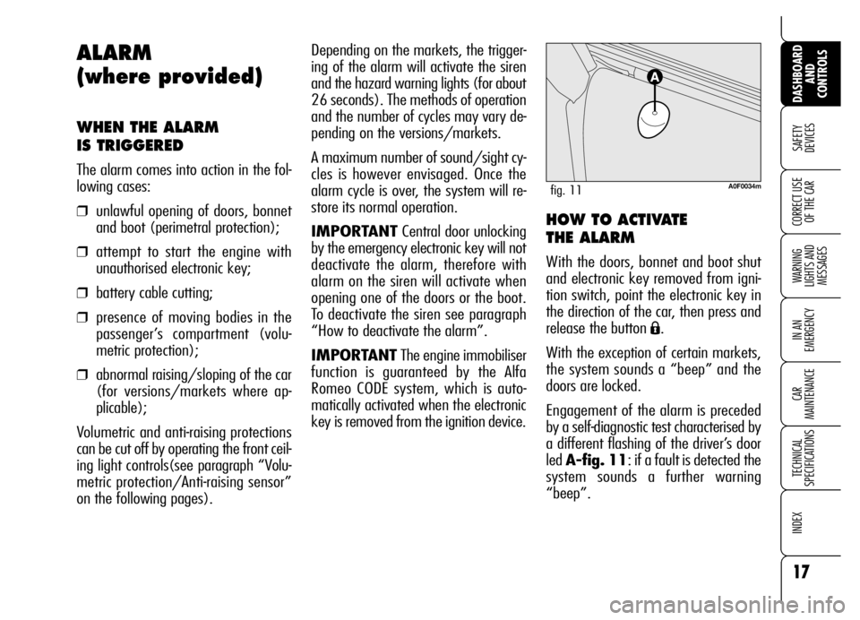
Engagement of the alarm is preceded
by a self-diagnostic test characterised by
a different flashing of the driver’s door
led A-fig. 11: if a fault is detected the
system sounds a further warning
“beep”.
ALARM
(where provided)
WHEN THE ALARM
IS TRIGGERED
The alarm comes into action in the fol-
lowing cases:
❒unlawful opening of doors, bonnet
and boot (perimetral protection);
❒attempt to start the engine with
unauthorised electronic key;
❒battery cable cutting;
❒presence of moving bodies in the
passenger’s compartment (volu-
metric protection);
❒abnormal raising/sloping of the car
(for versions/markets where ap-
plicable);
Volumetric and anti-raising protections
can be cut off by operating the front ceil-
ing light controls(see paragraph “Volu-
metric protection/Anti-raising sensor”
on the following pages).
A0F0034mfig. 11
Page 20 of 271
18
SAFETY
DEVICES
WARNING
LIGHTS AND
MESSAGES
IN AN
EMERGENCY
CAR
MAINTENANCE
TECHNICAL
SPECIFICATIONS
INDEX
DASHBOARD
AND
CONTROLS
CORRECT USE
OF THE CAR
HOW TO DEACTIVATE
THE ALARM
Press button Ë. The system will react as
follows (with the exception of certain
markets):
❒two brief flashes of the direction in-
dicators;
❒two brief “beeps”;
❒door unlocking.
The alarm can be deactivated by fitting
the electronic key into the ignition
switch.
IMPORTANTOn certain versions any
attempt to break in detected by the sys-
tem will be indicated by a warning mes-
sage on the instrument panel display
when fitting the electronic key into the
ignition switch.VOLUMETRIC PROTECTION/
ANTI-RAISING SENSORS
To make sure that the protection sensors
are working properly, check that win-
dows are shut.
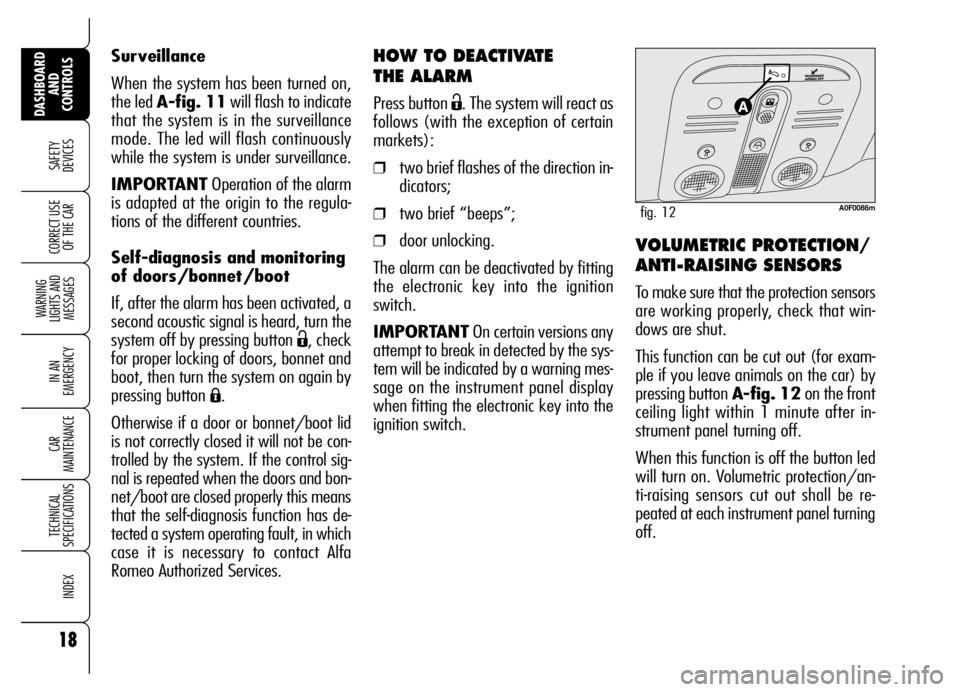
This function can be cut out (for exam-
ple if you leave animals on the car) by
pressing button A-fig. 12on the front
ceiling light within 1 minute after in-
strument panel turning off.
When this function is off the button led
will turn on. Volumetric protection/an-
ti-raising sensors cut out shall be re-
peated at each instrument panel turning
off. Surveillance
When the system has been turned on,
the led A-fig. 11will flash to indicate
that the system is in the surveillance
mode. The led will flash continuously
while the system is under surveillance.
IMPORTANTOperation of the alarm
is adapted at the origin to the regula-
tions of the different countries.
Self-diagnosis and monitoring
of doors/bonnet/boot
If, after the alarm has been activated, a
second acoustic signal is heard, turn the
system off by pressing button
Ë, check
for proper locking of doors, bonnet and
boot, then turn the system on again by
pressing button
Á.
Otherwise if a door or bonnet/boot lid
is not correctly closed it will not be con-
trolled by the system. If the control sig-
nal is repeated when the doors and bon-
net/boot are closed properly this means
that the self-diagnosis function has de-
tected a system operating fault, in which
case it is necessary to contact Alfa
Romeo Authorized Services.
A0F0086mfig. 12
Page 31 of 271
29
SAFETY
DEVICES
WARNING
LIGHTS AND
MESSAGES
IN AN
EMERGENCY
CAR
MAINTENANCE
TECHNICAL
SPECIFICATIONS
INDEX
DASHBOARD
AND
CONTROLS
CORRECT USE
OF THE CAR
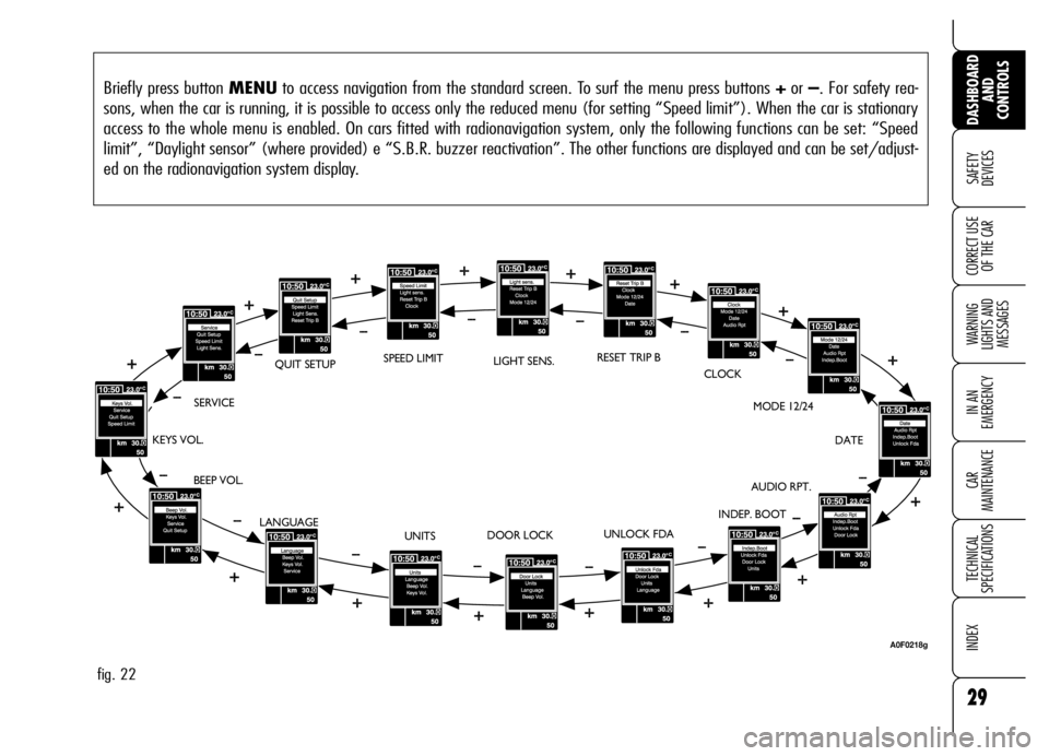
Briefly press button MENUto access navigation from the standard screen. To surf the menu press buttons +or –. For safety rea-
sons, when the car is running, it is possible to access only the reduced menu (for setting “Speed limit”). When the car is stationary
access to the whole menu is enabled. On cars fitted with radionavigation system, only the following functions can be set: “Speed
limit”, “Daylight sensor” (where provided) e “S.B.R. buzzer reactivation”. The other functions are displayed and can be set/adjust-
ed on the radionavigation system display.
fig. 22
BEEP VOL.SERVICEQUIT SETUPLIGHT SENS.RESET TRIP B
CLOCK
MODE 12/24
DATE
AUDIO RPT.
INDEP. BOOT
UNLOCK FDA
DOOR LOCK
UNITS KEYS VOL.
LANGUAGESPEED LIMIT
A0F0218g
Page 35 of 271

33
SAFETY
DEVICES
WARNING
LIGHTS AND
MESSAGES
IN AN
EMERGENCY
CAR
MAINTENANCE
TECHNICAL
SPECIFICATIONS
INDEX
DASHBOARD
AND
CONTROLS
CORRECT USE
OF THE CAR
Driver’s door unlocking
(Unlock Fda)
With this function it is possible to unlock
only the driver’s door by pressing the
electronic key button
Ë.
With this function active (ON) it is how-
ever possible to unlock the other doors
by pressing the door unlock button on
central console.
To activate/deactivate (ON/OFF) this
function proceed as follows:
❒briefly press button MENU: the dis-
play will show ONor OFF (ac-
cording to previous setting);
❒press button +or –for setting as re-
quired;
❒briefly press button MENUto go
back to the menu screen or press the
button for long to go back to the
standard screen.Automatic central door locking
(Door lock)
When activated (ON), this function
locks automatically the doors when the
car speed exceeds 20 km/h.
To activate/deactivate (ON/OFF) this
function proceed as follows:
❒briefly press buttonMENU: the dis-
play will show ONor OFF (ac-
cording to previous setting);
❒press button +or –for setting as re-
quired;
❒briefly press buttonMENUto go
back to the menu screen or press the
button for long to go back to the
standard screen.
When the function is on, the button
round led is on
q. Independent boot unlocking
(Indep. Boot)
Opening the boot with the remote con-
trol (press button
`is always pos-
sible. The option “Independent boot” en-
ables or disables the button set on the
armrest. More particularly: with “Indep.
Boot ON” the button is always off. With
“Indep. Boot OFF” the button is always
on and pressing it will unlock the boot if
doors are unlocked.
To activate independent boot function (by
deactivating the armrest button) (ON)
or to deactivate it (OFF), proceed as fol-
lows:
❒briefly press button MENU: the dis-
play will show ONor OFF (ac-
cording to previous setting);
❒press button +or –for setting as re-
quired;
❒briefly press button MENUto go
back to the menu screen or press the
button for long to go back to the
standard screen.
Page 93 of 271
91
SAFETY
DEVICES
WARNING
LIGHTS AND
MESSAGES
IN AN
EMERGENCY
CAR
MAINTENANCE
TECHNICAL
SPECIFICATIONS
INDEX
DASHBOARD
AND
CONTROLS
CORRECT USE
OF THE CARImproper boot closing is indicated by
symbol
Rand a message on the dis-
play (see section “Warning lights and
messages”).
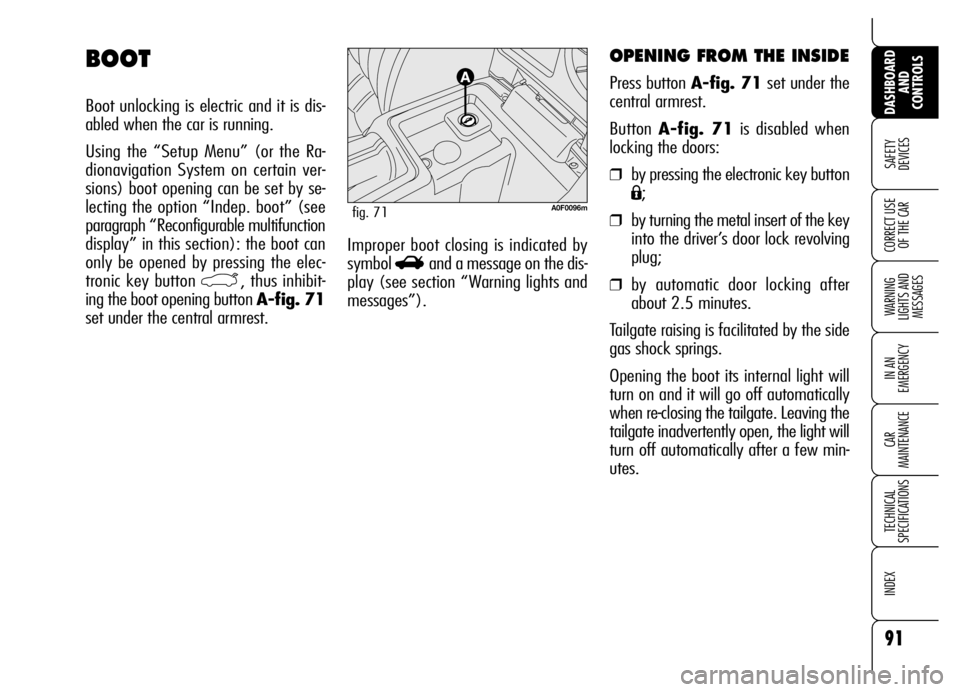
OPENING FROM THE INSIDE
Press button A-fig. 71set under the
central armrest.
Button A-fig. 71is disabled when
locking the doors:
❒by pressing the electronic key button
Á;
❒by turning the metal insert of the key
into the driver’s door lock revolving
plug;
❒by automatic door locking after
about 2.5 minutes.
Tailgate raising is facilitated by the side
gas shock springs.
Opening the boot its internal light will
turn on and it will go off automatically
when re-closing the tailgate. Leaving the
tailgate inadvertently open, the light will
turn off automatically after a few min-
utes.
BOOT
Boot unlocking is electric and it is dis-
abled when the car is running.
Using the “Setup Menu” (or the Ra-
dionavigation System on certain ver-
sions) boot opening can be set by se-
lecting the option “Indep. boot” (see
paragraph “Reconfigurable multifunction
display” in this section): the boot can
only be opened by pressing the elec-
tronic key button
`, thus inhibit-
ing the boot opening button A-fig. 71
set under the central armrest.
A0F0096mfig. 71
Page 94 of 271
92
SAFETY
DEVICES
WARNING
LIGHTS AND
MESSAGES
IN AN
EMERGENCY
CAR
MAINTENANCE
TECHNICAL
SPECIFICATIONS
INDEX
DASHBOARD
AND
CONTROLS
CORRECT USE
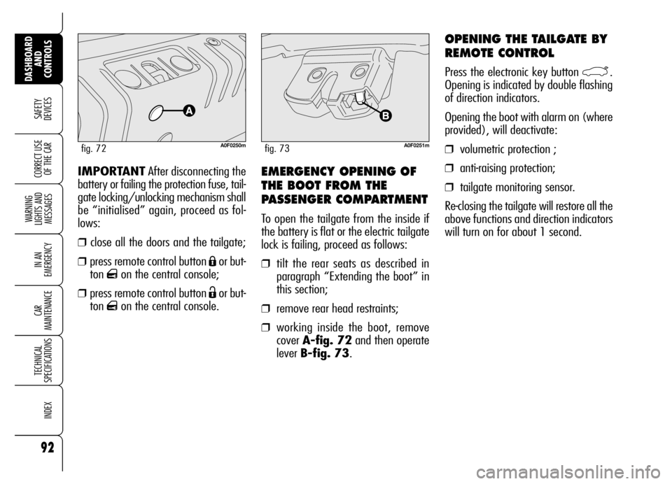
OF THE CAREMERGENCY OPENING OF
THE BOOT FROM THE
PASSENGER COMPARTMENT
To open the tailgate from the inside if
the battery is flat or the electric tailgate
lock is failing, proceed as follows:
❒tilt the rear seats as described in
paragraph “Extending the boot” in
this section;
❒remove rear head restraints;
❒working inside the boot, remove
cover A-fig. 72and then operate
lever B-fig. 73. IMPORTANTAfter disconnecting the
battery or failing the protection fuse, tail-
gate locking/unlocking mechanism shall
be “initialised” again, proceed as fol-
lows:
❒close all the doors and the tailgate;
❒press remote control button Áor but-
ton
qon the central console;
❒press remote control button Ëor but-
ton
qon the central console.
A0F0250mfig. 72
OPENING THE TAILGATE BY
REMOTE CONTROL
Press the electronic key button `.
Opening is indicated by double flashing
of direction indicators.
Opening the boot with alarm on (where
provided), will deactivate:
❒volumetric protection ;
❒anti-raising protection;
❒tailgate monitoring sensor.
Re-closing the tailgate will restore all the
above functions and direction indicators
will turn on for about 1 second.
A0F0251mfig. 73
Page 95 of 271
93
SAFETY
DEVICES
WARNING
LIGHTS AND
MESSAGES
IN AN
EMERGENCY
CAR
MAINTENANCE
TECHNICAL
SPECIFICATIONS
INDEX
DASHBOARD
AND
CONTROLS
CORRECT USE
OF THE CAR
TAILGATE CLOSING
Lower the tailgate pressing the lock un-
til hearing the locking click.
IMPORTANT Before closing the boot,
check whether you have with you the
ignition key since the tailgate will be
locked automatically.
The addition of objects
(speakers, spoilers, etc.)
on the rear shelf or boot
lid, except those envisaged by
the manufacturer, may prevent
the gas filled struts at the sides
of the boot from working prop-
erly.
When using the boot,
make sure the loads do
not exceed the permitted
weight (see “Technical specifi-
cations” chapter). Also make
sure the items in the boot are
arranged properly to prevent
them being thrown forwards
and injuring passengers should
you brake sharply.
WARNING
Never travel with ob-
jects on the rear shelf
to prevent them being thrown
forwards and injuring passen-
gers in case of accident or
sharp braking.
WARNING
EXTENDING THE BOOT
The double rear seat enables to extend
the boot totally or partially by splitting
one of the two seat section, thus ob-
taining different loading spaces accord-
ing to the number of rear passengers.
When driving at night
with heavy loads in the
boot, check and adjust, if re-
quired, the low beams
height (see paragraph “Head-
lights” in this section).
WARNING
Page 97 of 271

95
SAFETY
DEVICES
WARNING
LIGHTS AND
MESSAGES
IN AN
EMERGENCY
CAR
MAINTENANCE
TECHNICAL
SPECIFICATIONS
INDEX
DASHBOARD
AND
CONTROLS
CORRECT USE
OF THE CAR
To return the rear seat
back to its original position
Move aside the seat belts, check that
they are not twisted.
Raise the seat backrests and push them
back until hearing the locking click of
both retainers; the “red band” Baside
the levers Ashall no longer be visible.
The “red band” Bactually indicates that
the backrest is not properly secured.
Make sure the backrest
is properly secured at
both sides (“red bands” B-fig.
76 not visible) to prevent it
moves forward in the event of
sharp braking causing injuries
to passengers.
WARNING
ANCHORING THE LOAD
The boot houses 4 hooks for anchoring
ropes in order to guarantee perfect load
anchoring.
On certain versions, hooks B-fig. 78
can be located on the boot sides.
A0F0131mfig. 78
A heavy load that has
not been secured may
cause serious harm.
WARNING
If you want to carry
reserve fuel in a can,
follow law regulations, only
using a certified can, suitably
fastened to the load securing
eyelets. Even in this way the
risk of fire is increased in the
case of an accident.
WARNING