fuel cap Alfa Romeo Giulia 2017 Owner's Manual
[x] Cancel search | Manufacturer: ALFA ROMEO, Model Year: 2017, Model line: Giulia, Model: Alfa Romeo Giulia 2017Pages: 268, PDF Size: 18.64 MB
Page 65 of 268
Tachometer
The Tachometer indicates the engine
Revolutions Per Minute (RPM).
Adjusting Instrument Panel Lighting
(Brightness Sensor)
Inside the Tachometer there is a light
sensor capable of detecting light and
adjusting the brightness of the
instrument panel and the Connect
system display.
Engine Oil Temperature
Gauge
The digital indicator monitors the
temperature of the engine oil and starts
supplying indications when the oil
temperature reaches approximately
122° F (50°C).Under normal usage, the temperature
should remain around the middle of the
digital scale according to the working
conditions.
The
warning light will turn on to
signal the excessive increase of the
engine oil temperature.
In the event of excessive engine oil
temperature, stop the engine
immediately and contact an authorized
dealer.
Fuel Level Gauge
The digital fuel gauge monitors the
amount of fuel in the tank.
When the
warning light turns on, a
message is displayed, and a chime is
sound when 2.38 Gallons (9.0 L) of fuel
are left in the tank. Note:
If the low fuel warning light turns
on, refuel the vehicle at your nearest
fuel station.
Caution!
Do not travel with the fuel tank almost
empty: any gaps in fuel supply could
damage the catalytic converter.
Speedometer
The speedometer shows the vehicle
speed in miles per hour and/or
kilometers per hour (mph/km/h).
63
Page 92 of 268
SymbolWhat It Means What To Do
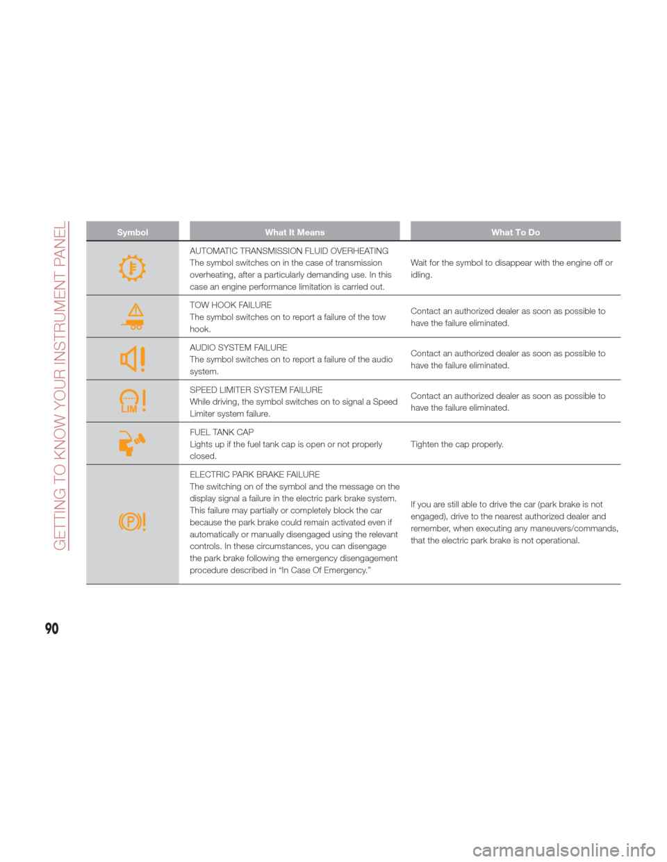
AUTOMATIC TRANSMISSION FLUID OVERHEATING
The symbol switches on in the case of transmission
overheating, after a particularly demanding use. In this
case an engine performance limitation is carried out.Wait for the symbol to disappear with the engine off or
idling.
TOW HOOK FAILURE
The symbol switches on to report a failure of the tow
hook.
Contact an authorized dealer as soon as possible to
have the failure eliminated.
AUDIO SYSTEM FAILURE
The symbol switches on to report a failure of the audio
system.Contact an authorized dealer as soon as possible to
have the failure eliminated.
SPEED LIMITER SYSTEM FAILURE
While driving, the symbol switches on to signal a Speed
Limiter system failure.Contact an authorized dealer as soon as possible to
have the failure eliminated.
FUEL TANK CAP
Lights up if the fuel tank cap is open or not properly
closed.
Tighten the cap properly.
ELECTRIC PARK BRAKE FAILURE
The switching on of the symbol and the message on the
display signal a failure in the electric park brake system.
This failure may partially or completely block the car
because the park brake could remain activated even if
automatically or manually disengaged using the relevant
controls. In these circumstances, you can disengage
the park brake following the emergency disengagement
procedure described in “In Case Of Emergency.”If you are still able to drive the car (park brake is not
engaged), drive to the nearest authorized dealer and
remember, when executing any maneuvers/commands,
that the electric park brake is not operational.
90
GETTING TO KNOW YOUR INSTRUMENT PANEL
Page 98 of 268
ACTIVE SAFETY
SYSTEMS
The vehicle may be equipped with the
following active safety devices:
Anti-Lock Braking (ABS) System
Drive Train Control (DTC) System
Electronic Stability Control (ESC)
System
Traction Control System (TCS)
Panic Brake Assist (PBA) System
Hill Start Assist (HSA) System
Dynamic Steering Torque (DST)
System
Active Torque Vectoring (ATV)
System
For the operation of the systems, see
the following pages.
Anti-Lock Braking (ABS)
System
An integral part of the braking system,
the ABS prevents one or more wheels
from locking and slipping in all road
surface conditions, regardless of the
intensity of the braking action. The
system ensures that the vehicle can be
controlled even during emergency
braking, allowing the driver to optimize
stopping distances.
The system intervenes during braking
when the wheels are about to lock,
typically in emergency braking or
low-grip conditions where locking may
be more frequent. The system also improves control and
stability of the vehicle when braking on
a surface where the grip of the left and
right wheels varies, such as in a corner.
The Electronic Braking Force
Distribution (EBD) system works with
the ABS, allowing the brake force to be
distributed between the front and rear
wheels.
System Intervention
The ABS equipped on this vehicle is
provided with the "Brake-by-wire"
(Integrated Brake System - IBS)
function. With this system, the
command given by pressing the brake
pedal is not transmitted hydraulically,
but electrically. Therefore, the light
pulsation that is felt on the pedal with
the traditional system is no longer
noticeable.Warning!
The ABS contains sophisticated
electronic equipment that may be
susceptible to interference caused by
improperly installed or high output radio
transmitting equipment. This interference
can cause possible loss of anti-lock braking
capability. Installation of such equipment
should be performed by qualified
professionals.
Pumping of the Anti-Lock Brakes will
diminish their effectiveness and may lead to
a collision. Pumping makes the stopping
distance longer. Just press firmly on your
brake pedal when you need to slow down
or stop.
The ABS cannot prevent the natural
laws of physics from acting on the vehicle,
nor can it increase braking or steering
efficiency beyond that afforded by the
condition of the vehicle brakes and tires or
the traction afforded.
The ABS cannot prevent collisions,
including those resulting from excessive
speed in turns, following another vehicle
too closely, or hydroplaning.
The capabilities of an ABS equipped
vehicle must never be exploited in a
reckless or dangerous manner that could
jeopardize the user’s safety or the safety of
others.
Drive Train Control
(DTC) System — If
Equipped
Some models of this vehicle are
equipped with an All-Wheel Drive
system (AWD), which offers an optimal
drive for countless driving conditions
and road surfaces. The system reduces
the slipping of the tires to a minimum,
automatically redistributing the torque
to the front and rear wheels as needed.
To maximize fuel savings, the vehicle
with AWD automatically passes to
rear-wheel drive (RWD) when the road
96
SAFETY
Page 174 of 268
Messages On The Display
If the trunk lid is lifted, the camera will
not detect any obstacle behind the
vehicle. The display will show a
dedicated warning message.
Make sure the trunk lid is closed by
pushing next to the lock until it clicks.
Important Notes
Ice, snow or mud on the surface of
the camera may reduce its sensitivity. It
is important to keep the camera surface
clean, and free from debris.
When parking, take care over
obstacles that may be above or under
the camera range.
REFUELING THE
VEHICLE
Refueling The Vehicle
Before refueling, make sure that the fuel
type is correct.
Also, stop the engine before refueling.
Note: An inefficient catalytic converter
leads to harmful exhaust emissions,
thus contributing to air pollution.
Caution!
Never introduce leaded fuel to the tank,
even in small amounts in an emergency, as
this would damage the catalytic converter
beyond repair.
Refueling Capacity
To ensure that you fill the tank
completely, top off twice after the first
click of the fuel nozzle.
Further top-off could cause faults in the
fuel feeding system.
Refueling Procedure
The fuel filler door is unlocked when the
central door locking system is
unlocked. It is automatically locked
when the central locking system is
applied. Opening The Fuel Filler Door
To refuel proceed as follows:
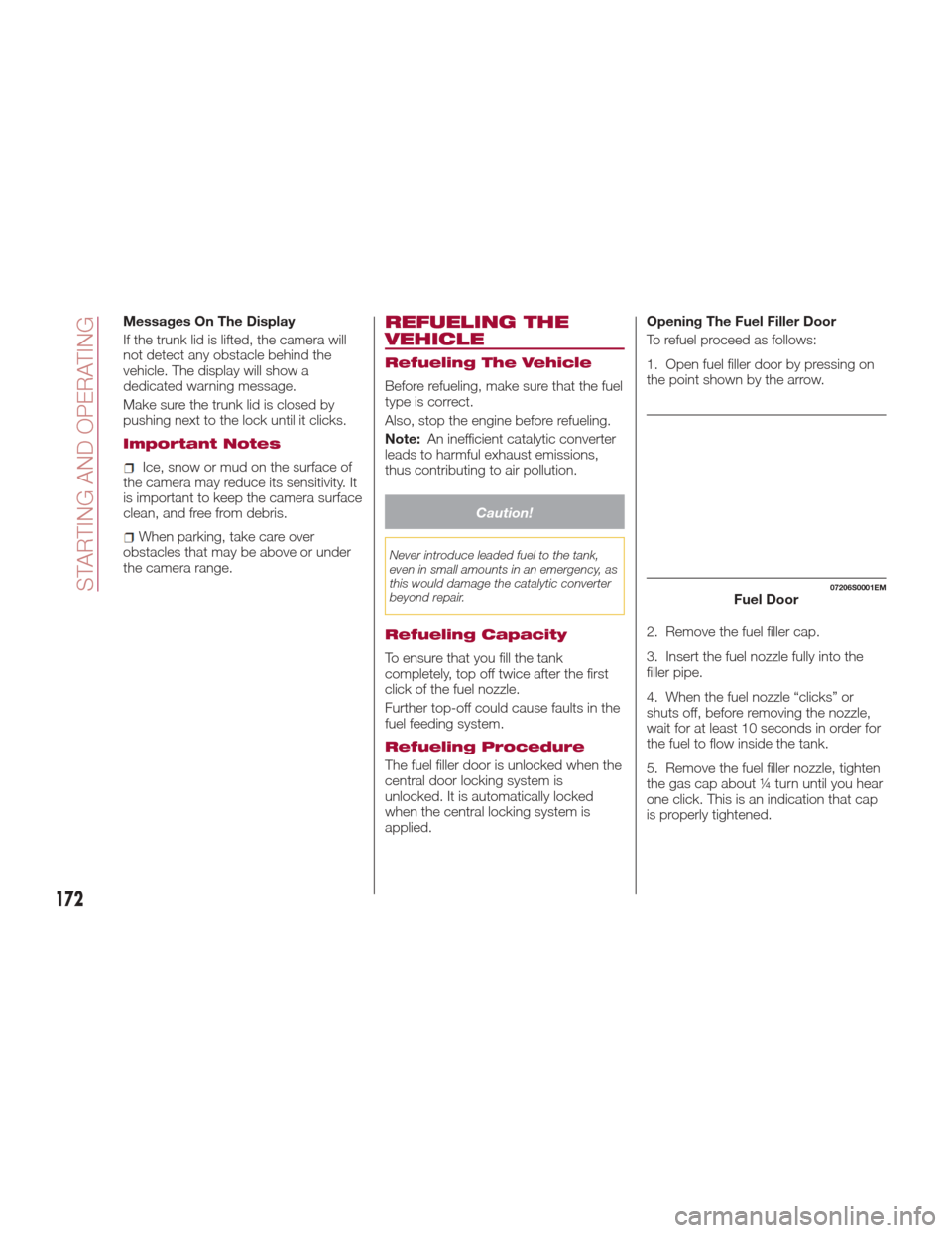
1. Open fuel filler door by pressing on
the point shown by the arrow.
2. Remove the fuel filler cap.
3. Insert the fuel nozzle fully into the
filler pipe.
4. When the fuel nozzle “clicks” or
shuts off, before removing the nozzle,
wait for at least 10 seconds in order for
the fuel to flow inside the tank.
5. Remove the fuel filler nozzle, tighten
the gas cap about ¼ turn until you hear
one click. This is an indication that cap
is properly tightened.
07206S0001EMFuel Door
172
STARTING AND OPERATING
Page 175 of 268
The label indicates the fuel type
(UNLEADED FUEL = gasoline).
Emergency Fuel Door Opening
In the event of an emergency the fuel
filler door can be opened by operating
from inside the trunk.
Proceed as follows:
1. Open the deck lid and reach the
emergency opening cable placed on
the side of the fuel filler
2. Pull the cord to unlock the fuel filler
door3. Open the fuel filler door by pressing
on it (see the previous instructions)
Warning!
Never have any smoking materials lit in
or near the vehicle when the fuel door is
open or the tank is being filled.
Never add fuel when the engine is
running. This is in violation of most state
and federal fire regulations and may cause
the MIL to turn on.
A fire may result if gasoline is pumped
into a portable container that is inside of a
vehicle. You could be burned. Always place
gas containers on the ground while filling.
Note: If the filler compartment is
washed with a pressure washer, keep it
at a distance of at least 8 inches
(20 cm).
VEHICLE LOADING
Certification Label
As required by National Highway Traffic
Safety Administration regulations, your
vehicle has a certification label affixed to
the driver's side door or pillar.
This label contains the month and year
of manufacture, Gross Vehicle Weight
Rating (GVWR), Gross Axle Weight
Rating (GAWR) front and rear, and
Vehicle Identification Number (VIN). A
Month-Day-Hour (MDH) number is
included on this label and indicates the
Month, Day and Hour of manufacture.
The bar code that appears on the
bottom of the label is your VIN.
Gross Vehicle Weight Rating
(GVWR)
The GVWR is the total permissible
weight of your vehicle including driver,
passengers, vehicle, options and cargo.
The label also specifies maximum
capacities of front and rear axle
systems (GAWR). Total load must be
limited so GVWR and front and rear
GAWR are not exceeded.
07206S0002EMFuel Door Label
173
Page 176 of 268
Payload
The payload of a vehicle is defined as
the allowable load weight a truck can
carry, including the weight of the driver,
all passengers, options and cargo.
Gross Axle Weight Rating
(GAWR)
The GAWR is the maximum permissible
load on the front and rear axles. The
load must be distributed in the cargo
area so that the GAWR of each axle is
not exceeded.
Each axle GAWR is determined by the
components in the system with the
lowest load carrying capacity (axle,
springs, tires or wheels). Heavier axles
or suspension components sometimes
specified by purchasers for increased
durability does not necessarily increase
the vehicle's GVWR.
Tire Size
The tire size on the Vehicle Certification
Label represents the actual tire size on
your vehicle. Replacement tires must be
equal to the load capacity of this tire
size.
Rim Size
This is the rim size that is appropriate
for the tire size listed.
Inflation Pressure
This is the cold tire inflation pressure for
your vehicle for all loading conditions up
to full GAWR.
Curb Weight
The curb weight of a vehicle is defined
as the total weight of the vehicle with all
fluids, including vehicle fuel, at full
capacity conditions, and with no
occupants or cargo loaded into the
vehicle. The front and rear curb weight
values are determined by weighing your
vehicle on a commercial scale before
any occupants or cargo are added.
Loading
The actual total weight and the weight
of the front and rear of your vehicle at
the ground can best be determined by
weighing it when it is loaded and ready
for operation.The entire vehicle should first be
weighed on a commercial scale to
insure that the GVWR has not been
exceeded. The weight on the front and
rear of the vehicle should then be
determined separately to be sure that
the load is properly distributed over the
front and rear axle. Weighing the vehicle
may show that the GAWR of either the
front or rear axles has been exceeded
but the total load is within the specified
GVWR. If so, weight must be shifted
from front to rear or rear to front as
appropriate until the specified weight
limitations are met. Store the heavier
items down low and be sure that the
weight is distributed equally. Stow all
loose items securely before driving.
Improper weight distributions can have
an adverse effect on the way your
vehicle steers and handles and the way
the brakes operate.
Caution!
Do not load your vehicle any heavier than
the GVWR or the maximum front and rear
GAWR. If you do, parts on your vehicle can
break, or it can change the way your
vehicle handles. This could cause you to
lose control. Also overloading can shorten
the life of your vehicle.
174
STARTING AND OPERATING
Page 232 of 268
Unequal tire pressures from one side of
the vehicle to the other can cause the
vehicle to drift to the right or left.
Always drive with each tire inflated to
the recommended cold tire inflation
pressure.
Both under-inflation and over-inflation
affect the stability of the vehicle and can
produce a feeling of sluggish response
or over responsiveness in the steering.
Note:
Unequal tire pressures from side to
side may cause erratic and
unpredictable steering response.
Unequal tire pressure from side to
side may cause the vehicle to drift left
or right.
Fuel Economy
Underinflated tires will increase tire
rolling resistance resulting in higher fuel
consumption.
Tread Wear
Improper cold tire inflation pressures
can cause abnormal wear patterns and
reduced tread life, resulting in the need
for earlier tire replacement.
Ride Comfort And Vehicle Stability
Proper tire inflation contributes to a
comfortable ride. Over-inflation
produces a jarring and uncomfortable
ride.
Tire Inflation Pressures
The proper cold tire inflation pressure is
listed on the driver's side B-Pillar or rear
edge of the driver's side door.
At least once a month:
Check and adjust tire pressure with a
good quality pocket-type pressure
gauge. Do not make a visual judgement
when determining proper inflation. Tires
may look properly inflated even when
they are under-inflated.
Inspect tires for signs of tire wear or
visible damage.
Caution!
After inspecting or adjusting the tire
pressure, always reinstall the valve stem
cap. This will prevent moisture and dirt
from entering the valve stem, which could
damage the valve stem.
Inflation pressures specified on the
placard are always “cold tire inflation
pressure”. Cold tire inflation pressure is
defined as the tire pressure after the
vehicle has not been driven for at least
three hours, or driven less than 1 mile
(1.6 km) after sitting for a minimum of
three hours. The cold tire inflation
pressure must not exceed the
maximum inflation pressure molded
into the tire sidewall. Check tire pressures more often if
subject to a wide range of outdoor
temperatures, as tire pressures vary
with temperature changes.
Tire pressures change by approximately
1 psi (7 kPa) per 12°F (7°C) of air
temperature change. Keep this in mind
when checking tire pressure inside a
garage, especially in the Winter.
Example: If garage temperature = 68°F
(20°C) and the outside temperature =
32°F (0°C) then the cold tire inflation
pressure should be increased by 3 psi
(21 kPa), which equals 1 psi (7 kPa) for
every 12°F (7°C) for this outside
temperature condition.
Tire pressure may increase from 2 to
6 psi (13 to 40 kPa) during operation.
DO NOT reduce this normal pressure
build up or your tire pressure will be too
low.
Tire Pressures For High Speed
Operation
The manufacturer advocates driving at
safe speeds and within posted speed
limits. Where speed limits or conditions
are such that the vehicle can be driven
at high speeds, maintaining correct tire
inflation pressure is very important.
Increased tire pressure and reduced
vehicle loading may be required for
high-speed vehicle operation. Refer to
your authorized tire dealer or original
equipment vehicle dealer for
230
SERVICING AND MAINTENANCE
Page 240 of 268
TECHNICAL SPECIFICATIONS
Everything you may find useful for
understanding how your vehicle is
made and works is contained in this
chapter and illustrated with data, tables
and graphics. For the enthusiasts and
the technician, but also just for those
who want to know every detail of their
vehicle.IDENTIFICATION DATA.........239
ENGINE..................240
POWERSUPPLY ............241
TRANSMISSION .............242
BRAKES ................. .243
SUSPENSION ..............244
STEERING SYSTEM ..........245 DIMENSIONS ..............246
WEIGHTS................
.248
FUEL REQUIREMENTS ........249
FLUID CAPACITIES ...........251
FLUIDS AND LUBRICANTS ......252
PERFORMANCE ............254
238
Page 253 of 268
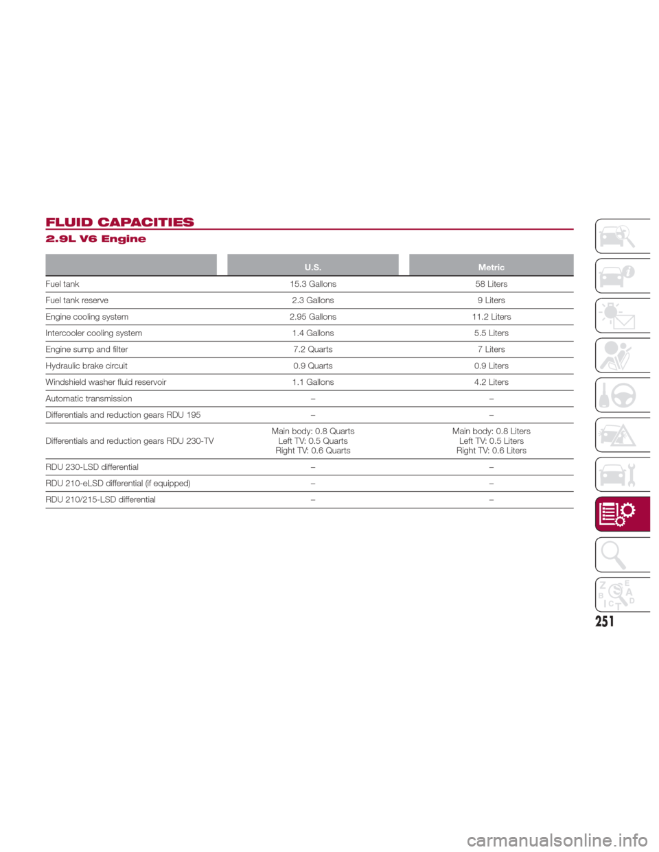
FLUID CAPACITIES
2.9L V6 Engine
U.S.Metric
Fuel tank 15.3 Gallons58 Liters
Fuel
tank reserve 2.3 Gallons9 Liters
Engine cooling system 2.95 Gallons11.2 Liters
Intercooler cooling system 1.4 Gallons5.5 Liters
Engine sump and filter 7.2 Quarts7 Liters
Hydraulic brake circuit 0.9 Quarts0.9 Liters
Windshield washer fluid reservoir 1.1 Gallons4.2 Liters
Automatic transmission ––
Differentials and reduction gears RDU 195 ––
Differentials and reduction gears RDU 230-TV Main body: 0.8 Quarts
Left TV: 0.5 Quarts
Right TV: 0.6 Quarts Main body: 0.8 Liters
Left TV: 0.5 Liters
Right TV: 0.6 Liters
RDU 230-LSD differential ––
RDU 210-eLSD differential (if equipped) ––
RDU 210/215-LSD differential ––
251