Servicing and maintenance Alfa Romeo Giulia 2018 Owner's Manual
[x] Cancel search | Manufacturer: ALFA ROMEO, Model Year: 2018, Model line: Giulia, Model: Alfa Romeo Giulia 2018Pages: 260, PDF Size: 6 MB
Page 4 of 260
READ THIS CAREFULLY
Refueling
Do not use fuel containing methanol or ethanol E85. Using these mixtures may cause misfiring and driving issues, as well as damage vital components
of the supply system.For further details on the use of the correct fuel, see the "Fuel Requirements" paragraph in the "Technical Specifications" chapter.
Starting The Engine
Make sure that the electric park brake is engaged and that the transmission is in PARK (P) or NEUTRAL (N). Next, press the brake pedal, and then push
the engine START/STOP button.
Parking On Flammable Material
The catalytic converter develops high temperatures during operation. Do not park the vehicle on grass, dry leaves, pine needles or other flammable
material: fire hazard.
Respecting The Environment
The vehicle is fitted with a system that carries out a continuous diagnosis of the emission-related components in order to help protect the
environment.
Electrical Accessories
If you decide to add electrical accessories after purchasing the vehicle, (with the risk of gradually draining the battery), contact your authorized
dealer. They can calculate the overall electrical requirement and check that the vehicle's electric system can support the required load.
Scheduled Servicing
Correctly performed maintenance procedures are essential for ensuring that your vehicle continuously maintains its quality in performance and
safety features, environmental friendliness, and low running costs.
Page 9 of 260
GRAPHICAL TABLE OF CONTENTS
GETTING TO KNOW YOUR VEHICLE
GETTING TO KNOW YOUR INSTRUMENT PANEL SAFETY
STARTING AND OPERATING IN CASE OF EMERGENCY
SERVICING AND MAINTENANCE TECHNICAL SPECIFICATIONS CUSTOMER ASSISTANCE INDEX
Page 52 of 260
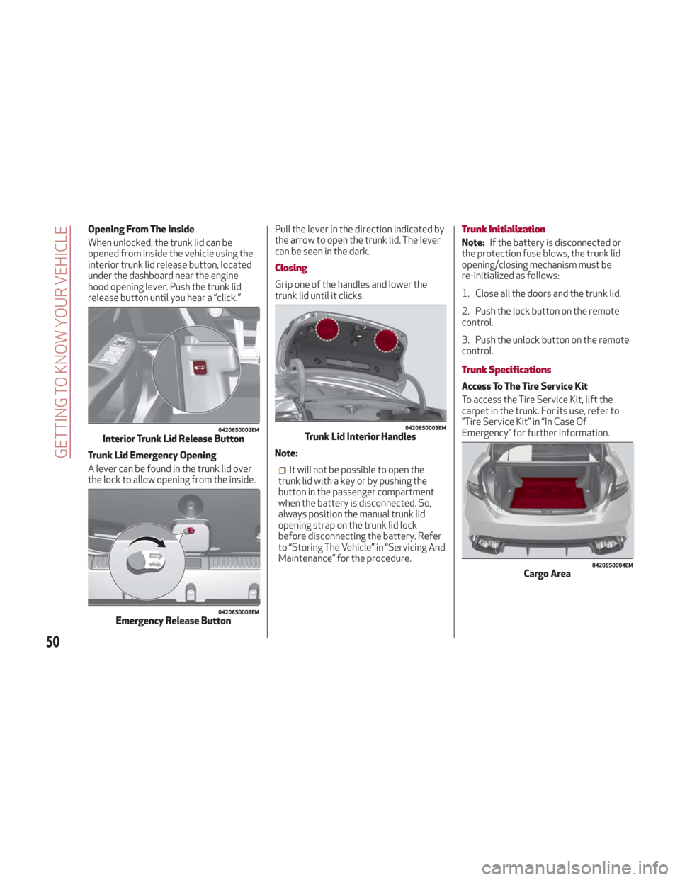
Opening From The Inside
When unlocked, the trunk lid can be
opened from inside the vehicle using the
interior trunk lid release button, located
under the dashboard near the engine
hood opening lever. Push the trunk lid
release button until you hear a “click.”
Trunk Lid Emergency Opening
A lever can be found in the trunk lid over
the lock to allow opening from the inside.Pull the lever in the direction indicated by
the arrow to open the trunk lid. The lever
can be seen in the dark.
Closing
Grip one of the handles and lower the
trunk lid until it clicks.
Note:
It will not be possible to open the
trunk lid with a key or by pushing the
button in the passenger compartment
when the battery is disconnected. So,
always position the manual trunk lid
opening strap on the trunk lid lock
before disconnecting the battery. Refer
to “Storing The Vehicle” in “Servicing And
Maintenance” for the procedure.
Trunk Initialization
Note: If the battery is disconnected or
the protection fuse blows, the trunk lid
opening/closing mechanism must be
re-initialized as follows:
1. Close all the doors and the trunk lid.
2. Push the lock button on the remote
control.
3. Push the unlock button on the remote
control.
Trunk Specifications
Access To The Tire Service Kit
To access the Tire Service Kit, lift the
carpet in the trunk. For its use, refer to
”Tire Service Kit” in “In Case Of
Emergency” for further information.
04206S0002EMInterior Trunk Lid Release Button
04206S0006EMEmergency Release Button
04206S0003EMTrunk Lid Interior Handles
04206S0004EMCargo Area
50
GETTING TO KNOW YOUR VEHICLE
Page 79 of 260
SymbolWhat It Means What To Do
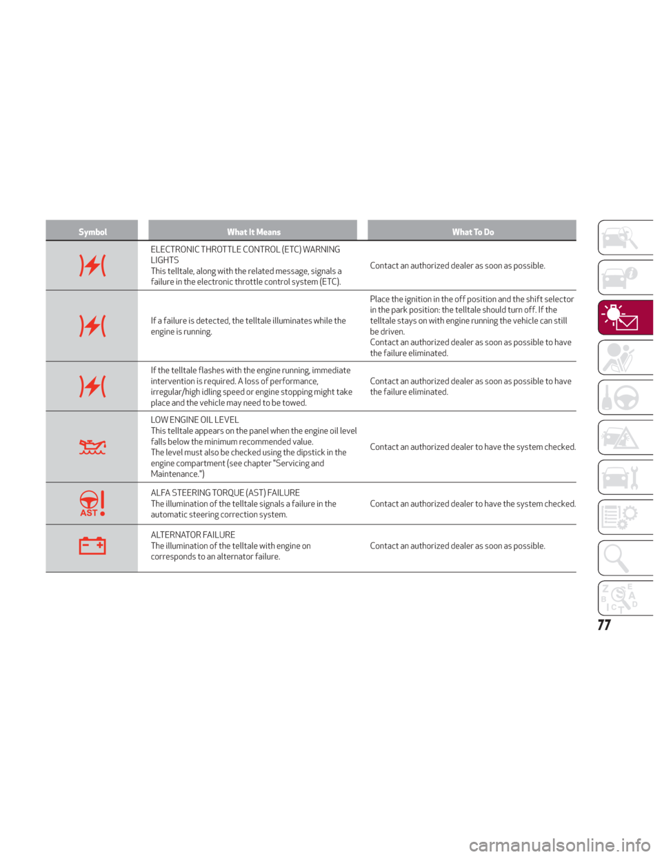
ELECTRONIC THROTTLE CONTROL (ETC) WARNING
LIGHTS
This telltale, along with the related message, signals a
failure in the electronic throttle control system (ETC).Contact an authorized dealer as soon as possible.
If a failure is detected, the telltale illuminates while the
engine is running.Place the ignition in the off position and the shift selector
in the park position: the telltale should turn off. If the
telltale stays on with engine running the vehicle can still
be driven.
Contact an authorized dealer as soon as possible to have
the failure eliminated.
If the telltale flashes with the engine running, immediate
intervention is required. A loss of performance,
irregular/high idling speed or engine stopping might take
place and the vehicle may need to be towed.
Contact an authorized dealer as soon as possible to have
the failure eliminated.
LOW ENGINE OIL LEVEL
This telltale appears on the panel when the engine oil level
falls below the minimum recommended value.
The level must also be checked using the dipstick in the
engine compartment (see chapter "Servicing and
Maintenance.")Contact an authorized dealer to have the system checked.
ALFA STEERING TORQUE (AST) FAILURE
The illumination of the telltale signals a failure in the
automatic steering correction system.
Contact an authorized dealer to have the system checked.
ALTERNATOR FAILURE
The illumination of the telltale with engine on
corresponds to an alternator failure.Contact an authorized dealer as soon as possible.
77
Page 85 of 260
SymbolWhat It Means What To Do
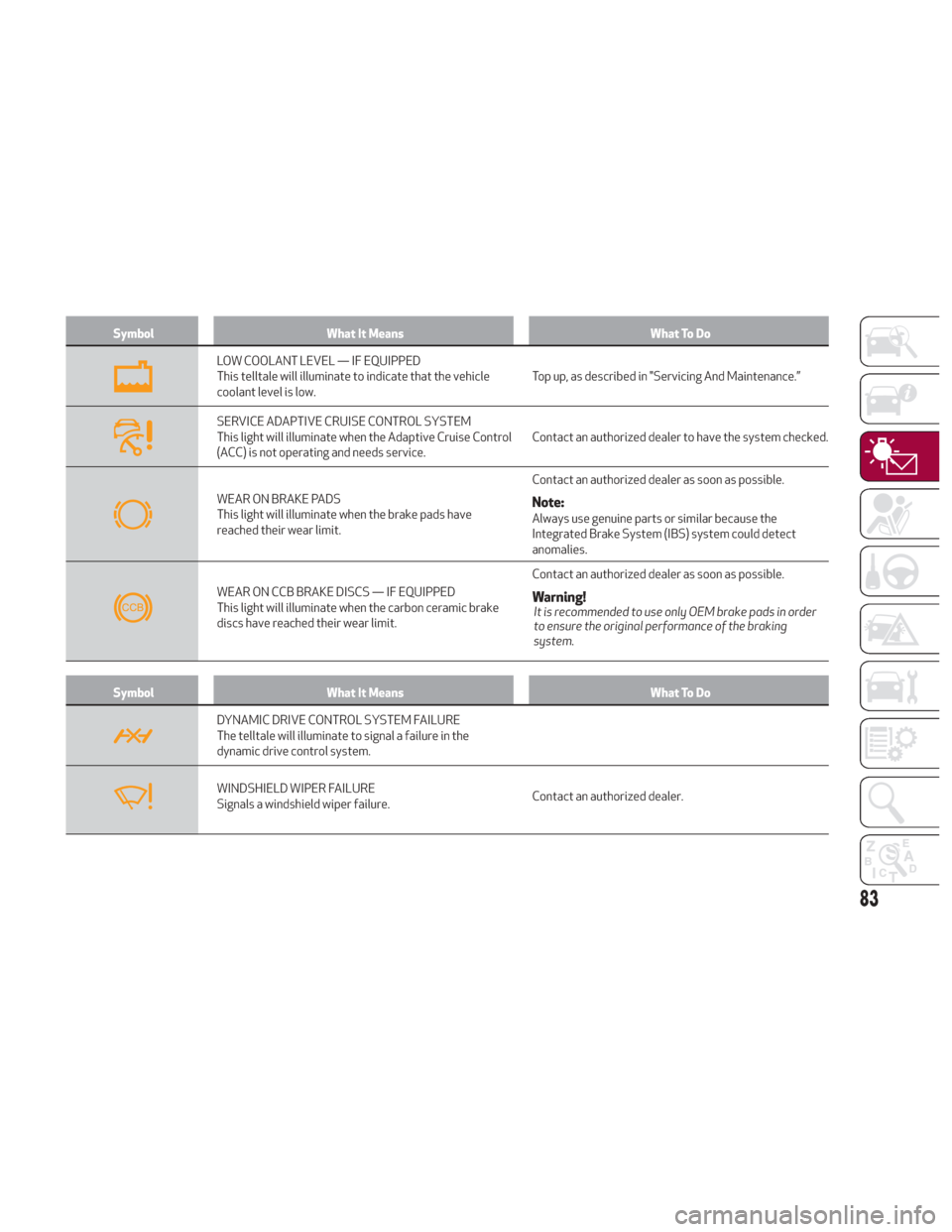
LOW COOLANT LEVEL — IF EQUIPPED
This telltale will illuminate to indicate that the vehicle
coolant level is low.Top up, as described in "Servicing And Maintenance.”
SERVICE ADAPTIVE CRUISE CONTROL SYSTEM
This light will illuminate when the Adaptive Cruise Control
(ACC) is not operating and needs service.Contact an authorized dealer to have the system checked.
WEAR ON BRAKE PADS
This light will illuminate when the brake pads have
reached their wear limit.Contact an authorized dealer as soon as possible.Note:Always use genuine parts or similar because the
Integrated Brake System (IBS) system could detect
anomalies.
WEAR ON CCB BRAKE DISCS — IF EQUIPPED
This light will illuminate when the carbon ceramic brake
discs have reached their wear limit.
Contact an authorized dealer as soon as possible.Warning!It is recommended to use only OEM brake pads in order
to ensure the original performance of the braking
system.
Symbol
What It Means What To Do
DYNAMIC DRIVE CONTROL SYSTEM FAILURE
The telltale will illuminate to signal a failure in the
dynamic drive control system.
WINDSHIELD WIPER FAILURE
Signals a windshield wiper failure.Contact an authorized dealer.
83
Page 86 of 260
SymbolWhat It Means What To Do
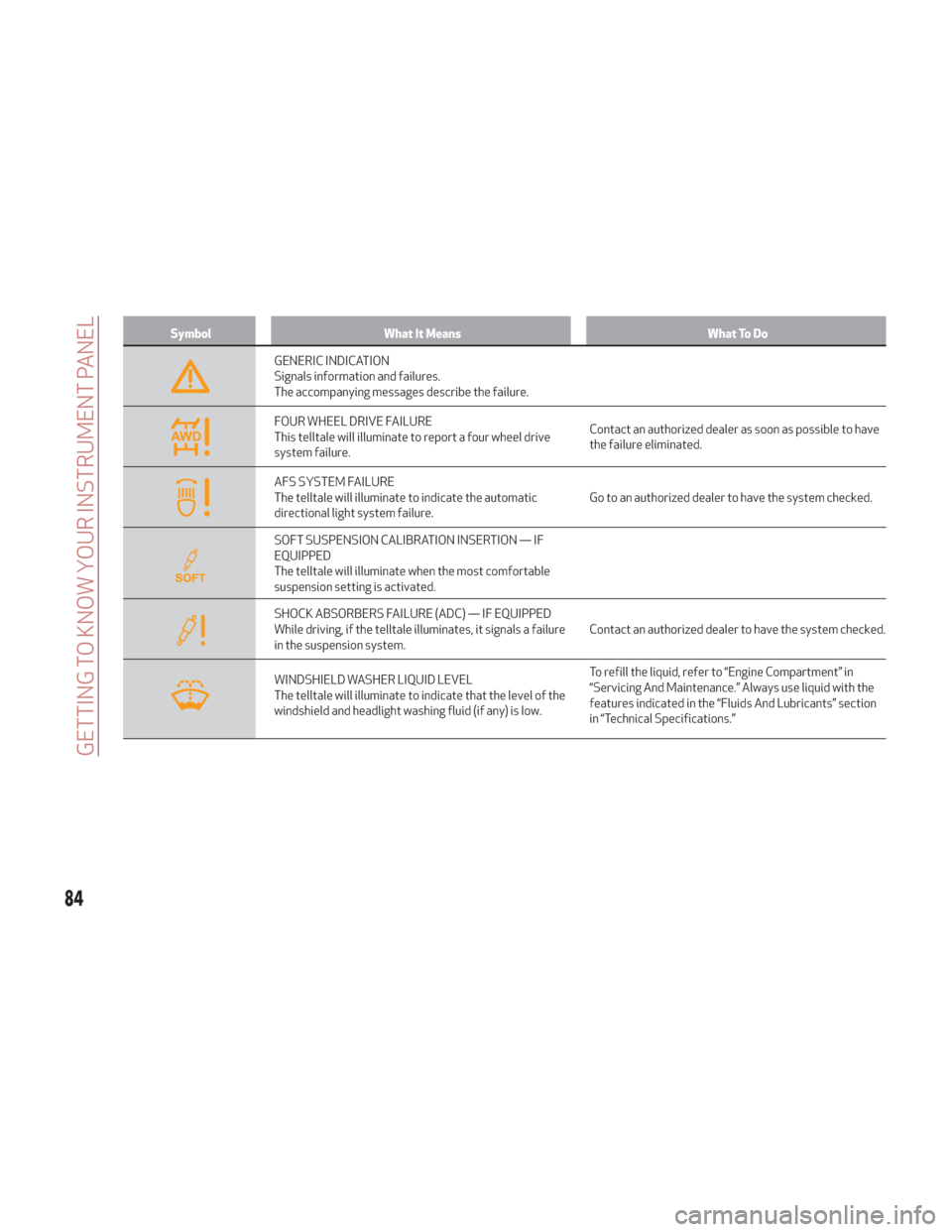
GENERIC INDICATION
Signals information and failures.
The accompanying messages describe the failure.
FOUR WHEEL DRIVE FAILURE
This telltale will illuminate to report a four wheel drive
system failure.Contact an authorized dealer as soon as possible to have
the failure eliminated.
AFS SYSTEM FAILURE
The telltale will illuminate to indicate the automatic
directional light system failure.
Go to an authorized dealer to have the system checked.
SOFT SUSPENSION CALIBRATION INSERTION — IF
EQUIPPED
The telltale will illuminate when the most comfortable
suspension setting is activated.
SHOCK ABSORBERS FAILURE (ADC) — IF EQUIPPED
While driving, if the telltale illuminates, it signals a failure
in the suspension system.Contact an authorized dealer to have the system checked.
WINDSHIELD WASHER LIQUID LEVEL
The telltale will illuminate to indicate that the level of the
windshield and headlight washing fluid (if any) is low.To refill the liquid, refer to “Engine Compartment” in
“Servicing And Maintenance.” Always use liquid with the
features indicated in the “Fluids And Lubricants” section
in “Technical Specifications.”
84
GETTING TO KNOW YOUR INSTRUMENT PANEL
Page 101 of 260
Warning!
The system has not been designed to
prevent impacts and cannot detect possible
conditions leading to an accident in
advance. Failure to take into account this
warning may lead to serious or fatal injuries.
The system may activate, assessing the
trajectory of the vehicle, for the presence of
reflecting metal objects different from
other vehicles, such as safety barriers, road
signs, barriers before parking lots, tollgates,
level crossings, gates, railways, objects near
road constructions sites or higher than the
vehicle (e.g. a fly-over). In the same way, the
system may intervene inside multi-story
parking lots or tunnels, or due to a glare on
the road surface. These possible activations
are a consequence of the real driving
scenario coverage by the system and must
not be regarded as faults.
The system has been designed for road
use only. If the vehicle is driven on a track,
the system must be deactivated to avoid
unnecessary warnings. Automatic
deactivation is signaled by the dedicated
warning light/symbol switching on in the
instrument panel (refer to the instructions in
the "Warning Lights And Messages On The
Instrument Panel" in "Getting To Know Your
Instrument Panel" for further information).
General Information
The following regulatory statement
applies to all Radio Frequency (RF)
devices equipped in this vehicle:
This device complies with Part 15 of the
FCC Rules and with Industry Canada
license-exempt RSS standard(s).
Operation is subject to the following
two conditions:
1. This device may not cause harmful
interference.
2. This device must accept any
interference received, including
interference that may cause undesired
operation.
Note:
Changes or modifications not
expressly approved by the party
responsible for compliance could void the
user’s authority to operate the equipment.
Tire Pressure Monitoring System
(TPMS)
This vehicle is equipped with a Tire
Pressure Monitoring System (TPMS) that
sends the inflation pressure information
of each tire to the control unit, and will
signal the driver in the event of
insufficient tire pressure.
Tire pressure will vary with temperature
by approximately 1 psi (7 kPa) for every
12°F (6.5°C). This means that when the
outside temperature decreases, the tire
pressure will also decrease. Tire pressure
should always be set based on cold inflation tire pressure. This is defined as
the tire pressure after the vehicle has not
been driven for at least three hours, or
driven less than 1 mile (1.6 km) after a
three hour period. The cold tire inflation
pressure must not exceed the maximum
inflation pressure molded into the tire
sidewall. Refer to “Tires” in “Servicing
And Maintenance” for information on
how to properly inflate the vehicle’s tires.
The tire pressure will also increase as the
vehicle is driven. This is normal, and there
should be no adjustment for this
increased pressure.
The TPMS will signal the driver if pressure
falls below the warning limit for any
reason, including the effects of low
temperature and normal loss of pressure
from the tire.
The TPMS will stop indicating insufficient
tire pressure when pressure is equal to or
greater than the prescribed cold inflation
level. Therefore, if insufficient tire
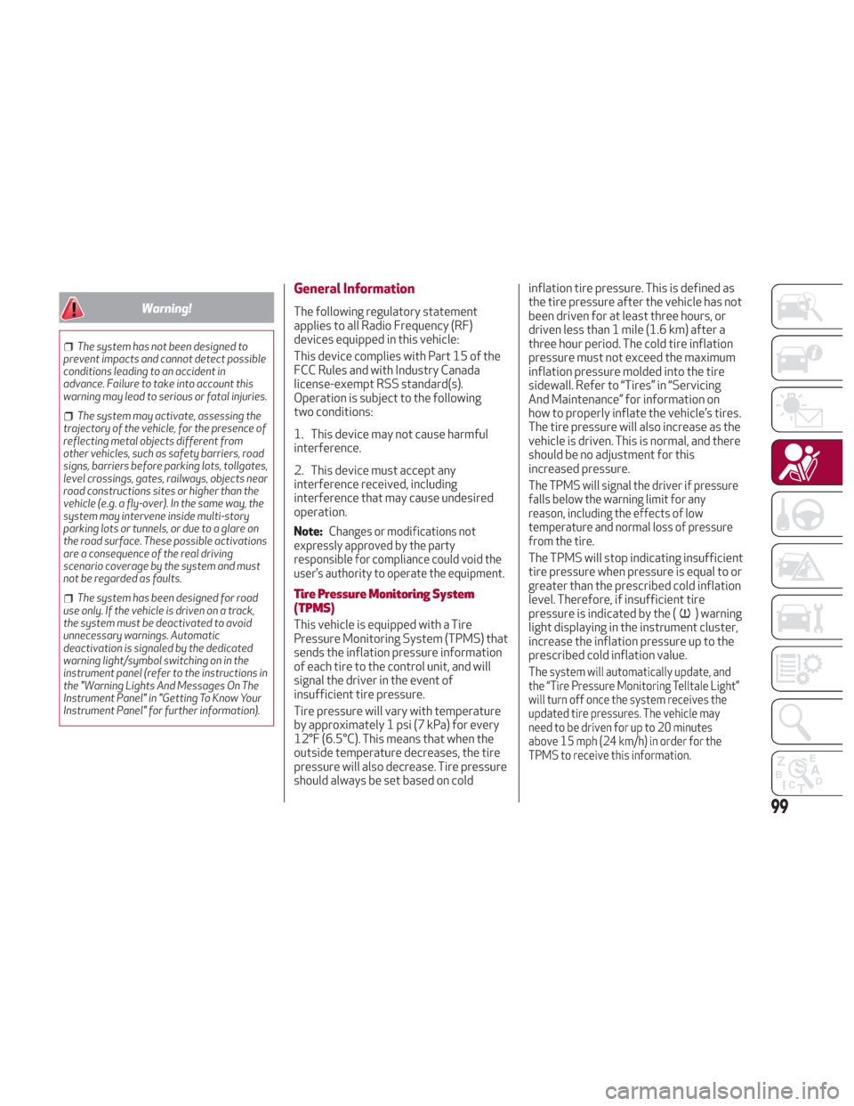
pressure is indicated by the (
) warning
light displaying in the instrument cluster,
increase the inflation pressure up to the
prescribed cold inflation value.
Thesystem will automatically update, and
the “Tire Pressure Monitoring Telltale Light”
will turn off once the system receives the
updated tire pressures. The vehicle may
need to be driven for up to 20 minutes
above 15 mph (24 km/h) in order for the
TPMS to receive this information.
99
Page 170 of 260
SUGGESTIONS FOR DRIVING
Saving Fuel
Below are some suggestions which may
help you save fuel and lower the amount
of harmful emissions released into the
atmosphere.
Vehicle Maintenance
Checks and operations should be carried
out in accordance with the Maintenance
Plan. Refer to "Scheduled Servicing" in
"Servicing And Maintenance" for further
information.
Tires
Check the tire pressures at least once
every four weeks: if the pressure is too
low, consumption levels increase as
resistance to rolling is higher.
Unnecessary Loads
Do not travel with an overloaded trunk.
The weight of the vehicle and its
arrangement greatly affect fuel
consumption and stability.
Electric Devices
Use electrical systems only for the
amount of time needed. The rear window
defroster, additional headlights,
windshield wipers and heater blower fan
require a considerable amount of energy;
increasing the current uptake increases
fuel consumption (by up to +25% when
city driving).Climate Control System
Using the climate control system will
increase consumption: use standard
ventilation when the temperature
outside permits.
Devices for Aerodynamic Control
The use of non-certified devices for
aerodynamic control may adversely
affect air drag and consumption levels.
Driving Style
Starting
Do not warm up the engine at low or high
revs when the vehicle is stationary; this
causes the engine to warm up more
slowly, thereby increasing fuel
consumption and emissions. It is
therefore advisable to drive off
immediately, slowly, avoiding high
speeds: by doing this the engine will
warm up more quickly.
Unnecessary Actions
Avoid revving up when starting at traffic
lights or before stopping the engine.
This action is unnecessary and causes
increased fuel consumption and pollution.
Gear Selection
Use a high gear when traffic and road
conditions allow it. Using a low gear for
faster acceleration will increase fuel
consumption. Improper use of a high gear
increases consumption, emissions and
engine wear.Max. Speed
Fuel consumption considerably increases
as speed increases. Maintain a constant
speed, avoiding unnecessary braking and
acceleration, which cost in terms of both
fuel consumption and emissions.
Acceleration
Accelerating violently severely affects
consumption and emissions: acceleration
should be gradual and should not exceed
the maximum torque.
Conditions Of Use
Cold Starting
Short trips and frequent cold starts will
not allow the engine to reach optimum
operating temperature. This results in a
significant increase in consumption
levels (from +15 to +30% in city driving)
and emissions.
Traffic And Road Conditions
High fuel consumption is caused by heavy
traffic, for instance when travelling in
traffic with frequent use of low gears or
in cities with many traffic lights. Winding
mountain roads and rough road surfaces
also adversely affect consumption.
Stops In Traffic
During prolonged stops (e.g. railway
crossings) turn off the engine.
168
STARTING AND OPERATING
Page 172 of 260
Brakes
The car braking system may be available
with four carbon-ceramic material brake
discs, one on each wheel.
In order to guarantee the maximum
braking capacity for the first use, Alfa
Romeo performs a "run-in" procedure for
discs and pads directly at the factory.
The use of carbon-ceramic material
brake discs guarantees braking features
(better deceleration/pedal load ratio,
braking distances, fading resistance)
proportional to the dynamic features of
the car in addition to considerably
decreasing the unsprung component
weight.
The materials used and the structural
features of the system could generate
unusual noises which have absolutely no
adverse effect on correct operation and
reliability of the braking system.
Greater pressure may need to be applied
to the brake pedal the first time to keep
the same braking capacities in presence
of condensation or salt on the braking
surfaces, for example after washing or if
the car is not used for a long time.
Note:Given the high technological level
of this system, any servicing on it must be
performed by your authorized dealer
which exclusively has the skills needed
for the repair operations. In case of intensive, high-performance
use of the car, have the efficiency of the
carbon-ceramic material braking system
inspected as shown on the Maintenance
Plan at your authorized dealer.
Driving On Race Tracks
Before driving on a track using a racing
style, it is necessary to:
Attend a race track driving course.
Check the liquid levels in the engine
compartment. For more information, see
the “Checking Levels” section in the
“Servicing And Maintenance” chapter.
Have the car inspected at your
authorized dealer.
Remember that the car was not designed
to be driven exclusive on the race track
and that this use increases stress and
component wear.
Preheating The Carbon Ceramic
Material Brake Discs
The brake discs must be warmed up to
make them fully efficient. You are
advised to perform the following
procedure:
Brake nine times from 80 mph to
18 mph (130 km/h to 30 km/h) with
deceleration equal to 0.7g (the
longitudinal acceleration value is shown
on the instrument panel display by
setting RACE mode and selecting the “Performance” page) with 20 second
intervals between brake applications;
keep the car at a speed comprised
between 37 mph and 62 mph (60 km/h
and 100 km/h) and do not brake for
4 minutes to allow the brakes to cool
down;
Then brake three times from 124 mph
to 18 mph (200 km/h to 30 km/h) with
deceleration equal to 1.1g (ABS
operation) with 30 second intervals
between brake applications; keep the car
at a speed comprised between 37 mph
and 62 mph (60 km/h and 100 km/h) and
do not brake for 5 minutes to allow the
brakes to cool down.
170
STARTING AND OPERATING
Page 186 of 260
If you are unsure of the condition of the
tire or the wheel.
Keep Tire Service Kit away from open
flames or heat sources.
A loose Tire Service Kit thrown forward in
a collision or hard stop could endanger the
occupants of the vehicle. Always stow the
Tire Service Kit in the place provided. Failure
to follow these warnings can result in
injuries that are serious or fatal to you, your
passengers, and others around you.
Take care not to allow the contents of
Tire Service Kit to come in contact with hair,
eyes, or clothing. Tire Service Kit sealant is
harmful if inhaled, swallowed, or absorbed
through the skin. It causes skin, eye, and
respiratory irritation. Flush immediately
with plenty of water if there is any contact
with eyes or skin. Change clothing as soon
as possible, if there is any contact with
clothing.
Tire Service Kit Sealant solution contains
latex. In case of an allergic reaction or rash,
consult a physician immediately. Keep Tire
Service Kit out of reach of children. If
swallowed, rinse mouth immediately with
plenty of water and drink plenty of water.
Do not induce vomiting! Consult a physician
immediately.
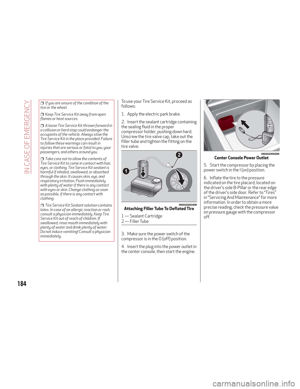
To use your Tire Service Kit, proceed as
follows:
1. Apply the electric park brake.
2. Insert the sealant cartridge containing
the sealing fluid in the proper
compressor holder, pushing down hard.
Unscrew the tire valve cap, take out the
filler tube and tighten the fitting on the
tire valve.
3. Make sure the power switch of the
compressor is in the O (off) position.
4. Insert the plug into the power outlet in
the center console, then start the engine. 5. Start the compressor by placing the
power switch in the I (on) position.
6. Inflate the tire to the pressure
indicated on the tire placard, located on
the driver’s side B-Pillar or the rear edge
of the driver’s side door. Refer to “Tires”
in “Servicing And Maintenance” for more
information. In order to obtain a more
precise reading, check the pressure value
on pressure gauge with the compressor
off.
08066S0004EMAttaching Filler Tube To Deflated Tire
1 — Sealant Cartridge
2 — Filler Tube
08066S0006EMCenter Console Power Outlet
184
IN CASE OF EMERGENCY