driver seat adjustment ALFA ROMEO GIULIA 2022 Owners Manual
[x] Cancel search | Manufacturer: ALFA ROMEO, Model Year: 2022, Model line: GIULIA, Model: ALFA ROMEO GIULIA 2022Pages: 248, PDF Size: 9.71 MB
Page 10 of 248
8
READ THIS CAREFULLY
Refueling..................................................... 2
Starting The Engine .................................... 2
Parking On Flammable Material ............... 2
Respecting The Environment .................... 2
Electrical Accessories ................................ 2
Scheduled Servicing .................................. 2
VEHICLE CHANGES /
ALTERATIONS
Accessories Purchased By The Owner ...... 3
Installing Electrical/Electronic Devices .... 3
Radio Transmitters And Mobile Phones ... 4
HOW TO USE THIS MANUAL
Operating Instructions ............................... 5
Warnings And Cautions.............................. 5
Symbols Key ............................................... 6
Symbols ...................................................... 6
Symbols Glossary ....................................... 7
GETTING TO KNOW YOUR
VEHICLE
KEYS..........................................................19
Key Fob .................................................. 19
ENGINE IMMOBILIZER SYSTEM ..............21
IGNITION SWITCH .....................................22
Keyless Push Button Ignition ................ 22
REMOTE START — IF EQUIPPED .............. 23
How To Use Remote Start ..................... 23
To Exit Remote Start Mode ................... 23
Remote Start Comfort Systems —
If Equipped ............................................. 23
VEHICLE SECURITY
SYSTEM — IF EQUIPPED .......................... 24
To Arm The System................................ 24
To Disarm The System .......................... 24
Volumetric/Anti-Lift Protection —
If Equipped ............................................. 24
DOORS ...................................................... 25
Power Door Locks.................................. 25
Locking The Doors With A Depleted
Battery .................................................... 25 Passive Entry System ........................... 26
Automatic Door Locks — If Equipped .. 27
Child-Protection Door Lock
System — Rear Doors ............................ 27
STEERING WHEEL.................................... 28
Manual Tilt/Telescoping Steering
Column ................................................... 28 Heated Steering Wheel —
If Equipped ............................................. 29
DRIVER MEMORY SETTINGS —
IF EQUIPPED ............................................ 30
Programming The Memory Feature ..... 30
Memory Position Recall ........................ 30
SEATS ....................................................... 30
Sparco Racing Seats
(Quadrifoglio Vehicles) — If Equipped .. 31 Manual Adjustment (Rear Seats) ......... 31 Power Adjustment (Front Seats) ...........33
Heated Seats — If Equipped .................35
Head Restraints .................................... 35
MIRRORS ..................................................37
Automatic Dimming Mirror ....................37
Vanity Mirror ...........................................37
Outside Power Mirrors ...........................38
Power Folding Outside Mirrors ..............38
Outside Automatic Dimming
Mirrors — If Equipped............................. 38 Heated Mirrors ......................................38
UNIVERSAL GARAGE DOOR OPENER
(HOMELINK®)
S....................................39
Before You Begin Programming
HomeLink® ............................................39 Erasing All The HomeLink® Channels ..39
Identifying Whether You Have A
Rolling Code Or Non-Rolling Code
Device .....................................................39 Programming HomeLink® To A
Garage Door Opener ..............................40 Programming HomeLink® To A
Miscellaneous Device ............................ 40 Reprogramming A Single HomeLink®
Button .....................................................41 Canadian/Gate Operator
Programming .......................................... 41 Security ...................................................41
Troubleshooting Tips..............................41
22_GA_OM_EN_USC_t.book Page 8
Page 32 of 248
GETTING TO KNOW YOUR VEHICLE
30
DRIVER MEMORY
SETTINGS — IF EQUIPPED
This feature allows the driver to store up to three
different memory profiles for easy recall through
a memory switch. Each memory profile saves
desired position settings for the following
features:
Driver seat
Side mirrors
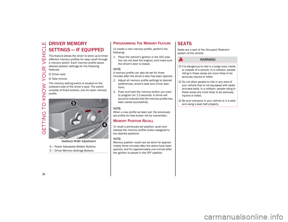
The memory setting switch is located on the
outboard side of the driver’s seat. The switch
consists of three buttons, one for each memory
profile.
Seatback Width Adjustment
PROGRAMMING THE MEMORY FEATURE
To create a new memory profile, perform the
following:
1. Place the vehicle’s ignition in the ACC posi -
tion (do not start the engine), and make sure
the driver’s door is closed.
NOTE:
A memory profile can also be set for three
minutes after the driver’s door has been opened.
2. Adjust all memory profile settings to desired preferences, driver’s seat and mirror posi -
tions.
3. Push and hold the memory button you want to program for 1.5 seconds. A chime will
sound to indicate that the memory profile has
been saved successfully.
NOTE:
When a new profile as been set, the previously
set profile for that button will be overwritten.
MEMORY POSITION RECALL
To recall a previously set position, push and
release the memory profile button assigned to
the desired positions.
NOTE:
Memory position recall can be done for approxi -
mately three minutes after the doors have been
opened, and for approximately one minute after
the ignition is placed in the OFF position.
SEATS
Seats are a part of the Occupant Restraint
system of the vehicle.
4 — Power Adjustable Bolster Buttons
5 — Driver Memory Settings Buttons
WARNING!
It is dangerous to ride in a cargo area, inside
or outside of a vehicle. In a collision, people
riding in these areas are more likely to be
seriously injured or killed.
Do not allow people to ride in any area of
your vehicle that is not equipped with seats
and seat belts. In a collision, people riding in
these areas are more likely to be seriously
injured or killed.
Be sure everyone in your vehicle is in a seat
and using a seat belt properly.
22_GA_OM_EN_USC_t.book Page 30
Page 35 of 248
33
Center Seatback Lowering
The center seatback can be folded forward for a
“Ski Pass-Through” feature from the trunk. Before
lowering the center seatback, make sure that the
rear center seat belt is not fastened and that
there are not any objects in the middle part of the
cushion.
Using the release strap, pull upward to release
the seatback and lower the center seatback
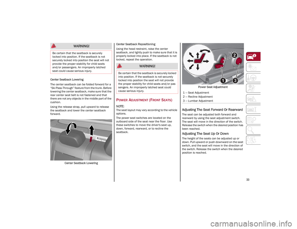
forward.Center Seatback Lowering Center Seatback Repositioning
Using the head restraint, raise the center
seatback, and lightly push to make sure that it is
properly locked into place. If the seatback is not
locked, repeat the operation.
POWER ADJUSTMENT (FRONT SEATS)
NOTE:
The seat layout may vary according to the vehicle
options.
The power seat switches are located on the
outboard side of the seat near the floor. Use
these switches to move the driver's seat up,
down, forward, rearward, or to recline the
seatback.
Power Seat AdjustmentAdjusting The Seat Forward Or Rearward
The seat can be adjusted both forward and
rearward by using the seat adjustment switch.
The seat will move in the direction of the switch.
Release the switch when the desired position has
been reached.
Adjusting The Seat Up Or Down
The height of the seats can be adjusted up or
down. Pull upward or push downward on the seat
switch, and the seat will move in the direction of
the switch. Release the switch when the desired
position is reached.
WARNING!
Be certain that the seatback is securely
locked into position. If the seatback is not
securely locked into position the seat will not
provide the proper stability for child seats
and/or passengers. An improperly latched
seat could cause serious injury.
WARNING!
Be certain that the seatback is securely locked
into position. If the seatback is not securely
locked into position the seat will not provide
the proper stability for child seats and/or pas -
sengers. An improperly latched seat could
cause serious injury.
1 — Seat Adjustment
2 — Recline Adjustment
3 — Lumbar Adjustment
22_GA_OM_EN_USC_t.book Page 33
Page 36 of 248
GETTING TO KNOW YOUR VEHICLE
34
Tilting The Seat Up Or Down — If Equipped
The seat angle can be adjusted in four directions.
Lift or push the front part of seat switch to move
the front part of the seat in the corresponding
direction. Release the seat switch when the seat
has reached the desired position.
Reclining The Seatback
The angle of the seatback can be adjusted
forward or rearward by using the recline switch.
The seat will move in the direction of the switch.
Release the switch when the desired position is
reached.
Power Lumbar
The power lumbar switch is located on the
outboard side of the power seat. Push the switch
forward or rearward to increase or decrease the
lumbar support. Push the switch upward or
downward to raise or lower the lumbar support.
Seat Cushion Extension — If Equipped
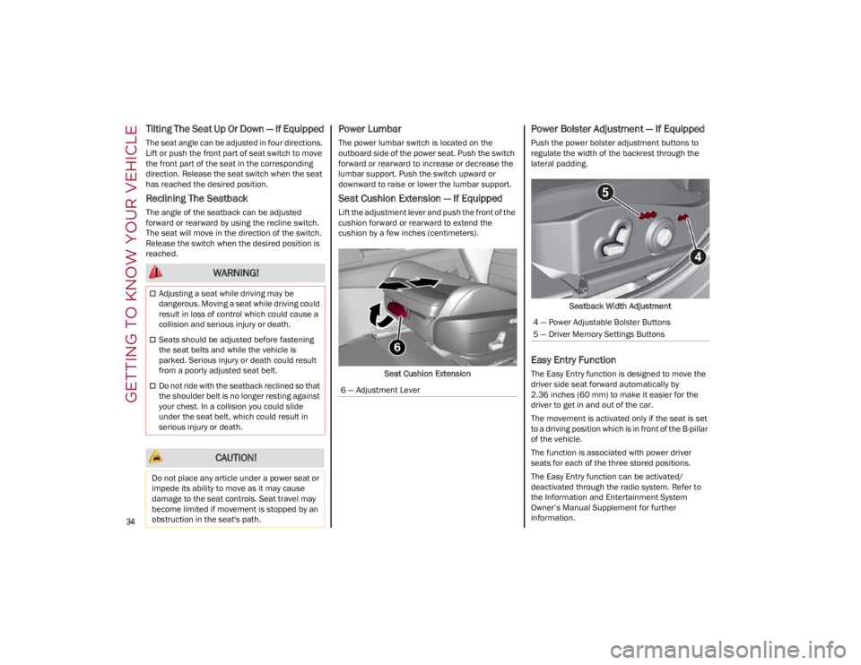
Lift the adjustment lever and push the front of the
cushion forward or rearward to extend the
cushion by a few inches (centimeters).Seat Cushion Extension
Power Bolster Adjustment — If Equipped
Push the power bolster adjustment buttons to
regulate the width of the backrest through the
lateral padding.
Seatback Width Adjustment
Easy Entry Function
The Easy Entry function is designed to move the
driver side seat forward automatically by
2.36 inches (60 mm) to make it easier for the
driver to get in and out of the car.
The movement is activated only if the seat is set
to a driving position which is in front of the B-pillar
of the vehicle.
The function is associated with power driver
seats for each of the three stored positions.
The Easy Entry function can be activated/
deactivated through the radio system. Refer to
the Information and Entertainment System
Owner’s Manual Supplement for further
information.
WARNING!
Adjusting a seat while driving may be
dangerous. Moving a seat while driving could
result in loss of control which could cause a
collision and serious injury or death.
Seats should be adjusted before fastening
the seat belts and while the vehicle is
parked. Serious injury or death could result
from a poorly adjusted seat belt.
Do not ride with the seatback reclined so that
the shoulder belt is no longer resting against
your chest. In a collision you could slide
under the seat belt, which could result in
serious injury or death.
CAUTION!
Do not place any article under a power seat or
impede its ability to move as it may cause
damage to the seat controls. Seat travel may
become limited if movement is stopped by an
obstruction in the seat's path.
6 — Adjustment Lever
4 — Power Adjustable Bolster Buttons
5 — Driver Memory Settings Buttons
22_GA_OM_EN_USC_t.book Page 34
Page 38 of 248
GETTING TO KNOW YOUR VEHICLE
36
(Continued)
Sparco Racing Seat Head Restraints
(Quadrifoglio Vehicles) — If Equipped
Head restraints on Sparco Racing Seats (front
seats) are non-adjustable and non-removable.
The non-adjustable head restraints consist of a
trimmed foam covering over the upper structure
of the seatbacks and are intended to help protect
you and the passenger from neck injury.
Adjust the seatbacks to their upright, on-road
positions so that the head restraint is positioned
as close as possible to the back of your head.
Front Head Restraints
The front head restraints may be
height-adjustable.
To raise the head restraint, pull up on the head
restraint until it clicks into place.
To lower the head restraint, push in the
adjustment button and lower the head restraint
to the desired height while holding the button.
Then, release the adjustment button.
NOTE:
To allow maximum visibility for the driver, if the
head restraints are not in use, lower the head
restraint all the way.
Rear Head Restraint Adjustment
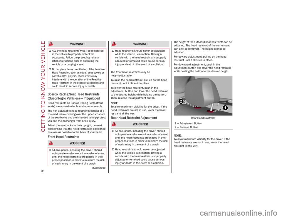
The height of the outboard head restraints can be
adjusted. The head restraint of the center seat
can only be removed. The height cannot be
adjusted.
For upward adjustment, pull up on the head
restraint until it clicks into place.
For downward adjustment, push in the
adjustment button and lower the head restraint
while holding the button to the desired height.Rear Head Restraint
NOTE:
To allow maximum visibility for the driver, if the
head restraints are not in use, lower the head
restraint all the way.
ALL the head restraints MUST be reinstalled
in the vehicle to properly protect the
occupants. Follow the preceding reinstal -
lation instructions prior to operating the
vehicle or occupying a seat.
Do not place items over the top of the Reactive
Head Restraint, such as coats, seat covers or
portable DVD players. These items may
interfere with the operation of the Reactive
Head Restraint in the event of a collision and
could result in serious injury or death.
WARNING!
All occupants, including the driver, should
not operate a vehicle or sit in a vehicle’s seat
until the head restraints are placed in their
proper positions in order to minimize the risk
of neck injury in the event of a crash.
WARNING!
Head restraints should never be adjusted
while the vehicle is in motion. Driving a
vehicle with the head restraints improperly
adjusted or removed could cause serious
injury or death in the event of a collision.
WARNING!
All occupants, including the driver, should
not operate a vehicle or sit in a vehicle’s seat
until the head restraints are placed in their
proper positions in order to minimize the risk
of neck injury in the event of a crash.
Head restraints should never be adjusted
while the vehicle is in motion. Driving a
vehicle with the head restraints improperly
adjusted or removed could cause serious
injury or death in the event of a collision.
WARNING!
1 — Adjustment Button
2 — Release Button
22_GA_OM_EN_USC_t.book Page 36
Page 39 of 248
37
Head Restraint Removal
To remove adjustable head restraints, proceed as
follows:
1. Raise the head restraints to their maximum height.
2. Push the adjustment button and the release button at the side of the two supports.
3. Remove the head restraints by pulling them upwards.
To reinstall the head restraints, proceed as
follows:
1. Hold down both the adjustment button and release button while placing the head
restraint post into the holes.
2. Then, reposition the head restraint to the appropriate height for the passengers.MIRRORS
AUTOMATIC DIMMING MIRROR
The rearview mirror can be adjusted up, down,
left, and right. The mirror should be adjusted to
center on the view through the rear window.
This mirror automatically adjusts for headlight
glare from vehicles behind you.
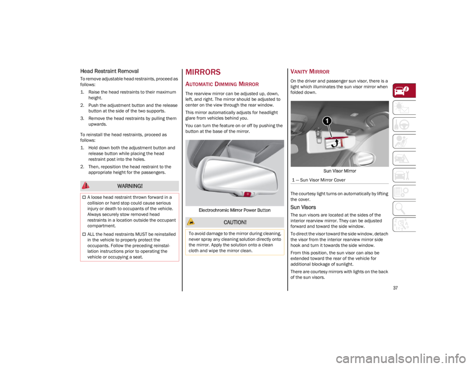
You can turn the feature on or off by pushing the
button at the base of the mirror.
Electrochromic Mirror Power Button
VANITY MIRROR
On the driver and passenger sun visor, there is a
light which illuminates the sun visor mirror when
folded down. Sun Visor Mirror
The courtesy light turns on automatically by lifting
the cover.
Sun Visors
The sun visors are located at the sides of the
interior rearview mirror. They can be adjusted
forward and toward the side window.
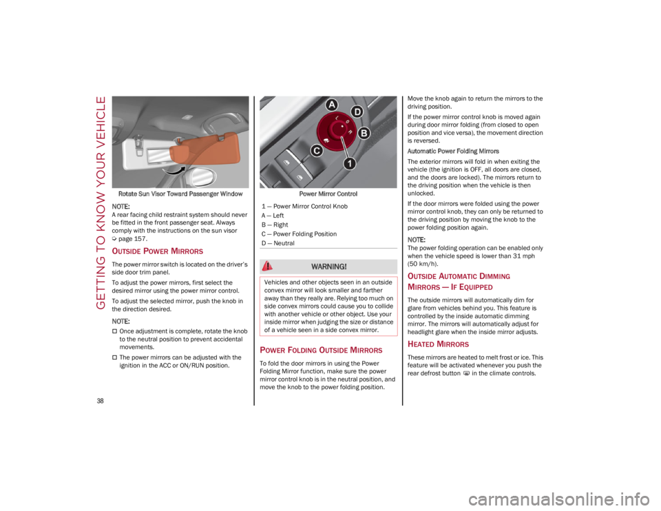
To direct the visor toward the side window, detach
the visor from the interior rearview mirror side
hook and turn it towards the side window.
From this position, the sun visor can also be
extended toward the rear of the vehicle for
additional blockage of sunlight.
There are courtesy mirrors with lights on the back
of the sun visors.
WARNING!
A loose head restraint thrown forward in a
collision or hard stop could cause serious
injury or death to occupants of the vehicle.
Always securely stow removed head
restraints in a location outside the occupant
compartment.
ALL the head restraints MUST be reinstalled
in the vehicle to properly protect the
occupants. Follow the preceding reinstal -
lation instructions prior to operating the
vehicle or occupying a seat.
CAUTION!
To avoid damage to the mirror during cleaning,
never spray any cleaning solution directly onto
the mirror. Apply the solution onto a clean
cloth and wipe the mirror clean.
1 — Sun Visor Mirror Cover
22_GA_OM_EN_USC_t.book Page 37
Page 40 of 248
GETTING TO KNOW YOUR VEHICLE
38
Rotate Sun Visor Toward Passenger Window
NOTE:
A rear facing child restraint system should never
be fitted in the front passenger seat. Always
comply with the instructions on the sun visor
Ú
page 157.
OUTSIDE POWER MIRRORS
The power mirror switch is located on the driver’s
side door trim panel.
To adjust the power mirrors, first select the
desired mirror using the power mirror control.
To adjust the selected mirror, push the knob in
the direction desired.
NOTE:
Once adjustment is complete, rotate the knob
to the neutral position to prevent accidental
movements.
The power mirrors can be adjusted with the
ignition in the ACC or ON/RUN position.Power Mirror ControlPOWER FOLDING OUTSIDE MIRRORS
To fold the door mirrors in using the Power
Folding Mirror function, make sure the power
mirror control knob is in the neutral position, and
move the knob to the power folding position. Move the knob again to return the mirrors to the
driving position.
If the power mirror control knob is moved again
during door mirror folding (from closed to open
position and vice versa), the movement direction
is reversed.
Automatic Power Folding Mirrors
The exterior mirrors will fold in when exiting the
vehicle (the ignition is OFF, all doors are closed,
and the doors are locked). The mirrors return to
the driving position when the vehicle is then
unlocked.
If the door mirrors were folded using the power
mirror control knob, they can only be returned to
the driving position by moving the knob to the
power folding position again.
NOTE:
The power folding operation can be enabled only
when the vehicle speed is lower than 31 mph
(50 km/h).
OUTSIDE AUTOMATIC DIMMING
M
IRRORS — IF EQUIPPED
The outside mirrors will automatically dim for
glare from vehicles behind you. This feature is
controlled by the inside automatic dimming
mirror. The mirrors will automatically adjust for
headlight glare when the inside mirror adjusts.
HEATED MIRRORS
These mirrors are heated to melt frost or ice. This
feature will be activated whenever you push the
rear defrost button in the climate controls.
1 — Power Mirror Control Knob
A — Left
B — Right
C — Power Folding Position
D — Neutral
WARNING!
Vehicles and other objects seen in an outside
convex mirror will look smaller and farther
away than they really are. Relying too much on
side convex mirrors could cause you to collide
with another vehicle or other object. Use your
inside mirror when judging the size or distance
of a vehicle seen in a side convex mirror.
22_GA_OM_EN_USC_t.book Page 38
Page 47 of 248
45
FRONT MAP READING LIGHTS
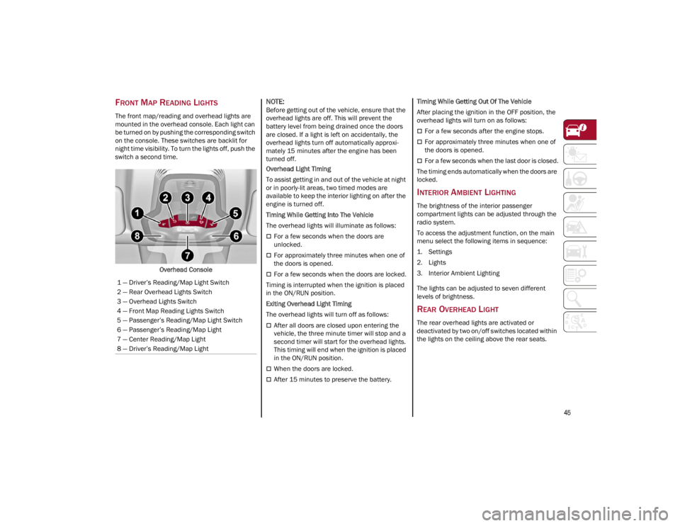
The front map/reading and overhead lights are
mounted in the overhead console. Each light can
be turned on by pushing the corresponding switch
on the console. These switches are backlit for
night time visibility. To turn the lights off, push the
switch a second time.Overhead Console
NOTE:
Before getting out of the vehicle, ensure that the
overhead lights are off. This will prevent the
battery level from being drained once the doors
are closed. If a light is left on accidentally, the
overhead lights turn off automatically approxi -
mately 15 minutes after the engine has been
turned off.
Overhead Light Timing
To assist getting in and out of the vehicle at night
or in poorly-lit areas, two timed modes are
available to keep the interior lighting on after the
engine is turned off.
Timing While Getting Into The Vehicle
The overhead lights will illuminate as follows:
For a few seconds when the doors are
unlocked.
For approximately three minutes when one of
the doors is opened.
For a few seconds when the doors are locked.
Timing is interrupted when the ignition is placed
in the ON/RUN position.
Exiting Overhead Light Timing
The overhead lights will turn off as follows:
After all doors are closed upon entering the
vehicle, the three minute timer will stop and a
second timer will start for the overhead lights.
This timing will end when the ignition is placed
in the ON/RUN position.
When the doors are locked.
After 15 minutes to preserve the battery. Timing While Getting Out Of The Vehicle
After placing the ignition in the OFF position, the
overhead lights will turn on as follows:
For a few seconds after the engine stops.
For approximately three minutes when one of
the doors is opened.
For a few seconds when the last door is closed.
The timing ends automatically when the doors are
locked.
INTERIOR AMBIENT LIGHTING
The brightness of the interior passenger
compartment lights can be adjusted through the
radio system.
To access the adjustment function, on the main
menu select the following items in sequence:
1. Settings
2. Lights
3. Interior Ambient Lighting
The lights can be adjusted to seven different
levels of brightness.
REAR OVERHEAD LIGHT
The rear overhead lights are activated or
deactivated by two on/off switches located within
the lights on the ceiling above the rear seats.
1 — Driver’s Reading/Map Light Switch
2 — Rear Overhead Lights Switch
3 — Overhead Lights Switch
4 — Front Map Reading Lights Switch
5 — Passenger’s Reading/Map Light Switch
6 — Passenger’s Reading/Map Light
7 — Center Reading/Map Light
8 — Driver’s Reading/Map Light
22_GA_OM_EN_USC_t.book Page 45
Page 51 of 248
49
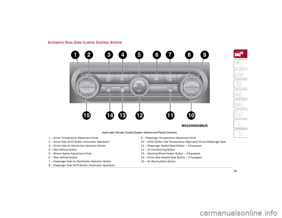
AUTOMATIC DUAL-ZONE CLIMATE CONTROL SYSTEM
Automatic Climate Control System (Instrument Panel Controls)
1 — Driver Temperature Adjustment Knob 9 — Passenger Temperature Adjustment Knob
2 — Driver Side AUTO Button (Automatic Operation) 10 — SYNC Button (Set Temperature Alignment) Driver/Passenger Side
3 — Driver Side Air Distribution Selection Button 11 — Passenger Heated Seat Button — If Equipped
4 — Max Defrost Button 12 — Air Conditioning Button
5 — Blower Speed Adjustment Knob 13 — Steering Wheel Heater Button — If Equipped
6 — Rear Defrost Button 14 — Driver Side Heated Seat Button — If Equipped
7 — Passenger Side Air Distribution Selection Button 15 — Air Recirculation Button
8 — Passenger Side AUTO Button (Automatic Operation)
22_GA_OM_EN_USC_t.book Page 49
Page 97 of 248
95
OPERATING MODE
Stopping the Engine
With vehicle at a standstill and brake pedal
pressed, the engine switches off if the gear
selector is in a position other than REVERSE (R).
The system does not operate when the gear
selector is in REVERSE (R), in order to make
parking maneuvers easier.
In the event of stops uphill, engine switching off is
disabled to make the “Hill Start Assist” function
available (works only with running engine).
NOTE:
The engine can only be automatically stopped
after having run at about 6 mph (10 km/h). After
an automatic restart, the vehicle only needs to
exceed a speed of 0.3 mph (0.5 km/h) to stop the
engine.
Engine stopping is signaled by the symbol
lighting up on the instrument cluster display.
Restarting the Engine
To restart the engine, release the brake pedal or
turn the steering wheel slightly (if equipped).
With the brake pressed and the transmission in
automatic mode DRIVE (D), the engine will restart
by shifting to REVERSE (R), to PARK (P) or to
“AutoStick”.
With the brake pressed while the gear selector is
in “AutoStick” mode, the engine will restart by
shifting to PARK (P) or by moving the selector
to + or -.
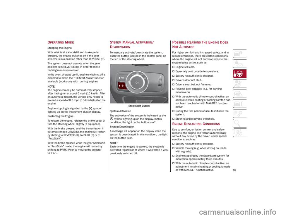
SYSTEM MANUAL ACTIVATION/
D
EACTIVATION
To manually activate/deactivate the system,
push the button located in the control panel on
the left of the steering wheel.
Stop/Start Button
System Activation
The activation of the system is indicated by the symbol lighting up on the display. In this
condition, the light on the button is off.
System Deactivation
A message will appear on the display when the
system is deactivated. In this condition, the light
on the button is on.
NOTE:
Each time the engine is started, the system is
activated regardless of where it was when it was
previously switched off.
POSSIBLE REASONS THE ENGINE DOES
N
OT AUTOSTOP
For higher comfort and increased safety, and to
reduce emissions, there are certain conditions
where the engine will not autostop despite the
system being active, such as:
Engine still cold.
Especially cold outside temperature.
Battery not sufficiently charged.
Driver's door not shut.
Driver's seat belt not fastened.
Reverse gear engaged (e.g. for parking
maneuvers).
With the automatic climate control active, an
adequate cabin heating or cooling comfort has
not been reached or with MAX-DEF function
active.
During the first period of use, to initialize the
system.
Steering angle beyond threshold.
ENGINE RESTARTING CONDITIONS
Due to comfort, emission control and safety
reasons, the engine can restart automatically
without any action by the driver, under special
conditions, such as:
Battery not sufficiently charged.
Vehicle moving (e.g. when driving on roads
with a grade).
Engine stopping by the Stop/Start system for
more than approximately three minutes.
With the automatic climate control active, an
adjustment in cabin heating or cooling is made
or with MAX-DEF function active.
22_GA_OM_EN_USC_t.book Page 95