oil temperature ALFA ROMEO GIULIA 2022 Owners Manual
[x] Cancel search | Manufacturer: ALFA ROMEO, Model Year: 2022, Model line: GIULIA, Model: ALFA ROMEO GIULIA 2022Pages: 248, PDF Size: 9.71 MB
Page 11 of 248
9
EXTERIOR LIGHTS ....................................42
Headlight Switch .................................... 42
Daytime Running Lights (DRLs) ............ 42
High Beam Headlights ........................... 42
Automatic Headlights ........................... 43
Flash-To-Pass ......................................... 43
Automatic High Beam Headlights —
If Equipped ............................................. 43 Parking Lights ........................................ 43
Headlight Off Delay ................................ 44
Rear Fog Light ........................................ 44
Adaptive Frontlight System
(AFS Function) — If Equipped ................ 44 Turn Signals ........................................... 44
Lane Change Assist ............................... 44
Static Bending Light Function
(SBL) — If Equipped ............................... 44
INTERIOR LIGHTS .....................................44
Front Map Reading Lights ..................... 45
Interior Ambient Lighting ....................... 45
Rear Overhead Light .............................. 45
Instrument Panel Dimmer Control ....... 46
WINDSHIELD WIPERS AND WASHERS....46
Windshield Wiper Operation ................. 46
Rain Sensing Wipers.............................. 47
Headlight Washers — If Equipped......... 48
CLIMATE CONTROL .................................48
Automatic Dual-Zone Climate Control
System ................................................... 49
INTERIOR STORAGE AND EQUIPMENT....55
Glove Compartment .............................. 55
Center Console ...................................... 55
Power Outlet........................................... 55 Cigar Lighter And Ash Tray —
If Equipped .............................................56 Wireless Charging Pad — If Equipped ...57
POWER WINDOWS................................... 57
Power Window Controls .........................57
Auto-Up Feature With Anti-Pinch
Protection ............................................... 58 Power Window System Initialization .....58
Wind Buffeting .......................................58
POWER SUNROOF — IF EQUIPPED ......... 58
Power Sunroof ........................................ 58
Opening And Closing The Sunroof ........59
Venting Sunroof......................................59
Sunshade Operation ..............................59
Pinch Protect Feature ............................59
Re-Initialization Procedure ....................59
Sunroof Maintenance ............................60
HOOD ...................................................... 60
Opening The Hood ................................. 60
Closing The Hood ...................................61
TRUNK ...................................................... 61
Opening...................................................61
Closing ....................................................62
Trunk Initialization..................................62
Trunk Specifications .............................62
ENVIRONMENTAL PROTECTION
SYSTEMS ................................................. 63
ACTIVE AERODYNAMIC SPOILER
(QUADRIFOGLIO VEHICLES) .................... 63
Carbon Fiber Active Aero Front
Spoiler .....................................................63
GETTING TO KNOW YOUR
INSTRUMENT PANEL
INSTRUMENT PANEL FEATURES ............ 64
Instrument Cluster ................................ 64
Tachometer............................................ 65
Engine Oil Temperature Gauge ............ 65
Fuel Level Gauge ................................... 66
Speedometer ......................................... 66
INSTRUMENT CLUSTER DISPLAY ........... 66
Instrument Cluster Display
Description ............................................. 66 Reconfigurable Instrument Cluster
Display .................................................... 66 Reconfigurable Display Items ............... 66
Customer Programmable Settings ....... 69
WARNING LIGHTS AND MESSAGES ON
THE INSTRUMENT PANEL ....................... 70
Red Warning Lights ............................... 70
Amber Warning Lights ........................... 72
Green Indicator Lights........................... 74
Blue Indicator Lights ............................. 74
Red Symbols .......................................... 74
Amber Symbols ...................................... 76
Green Symbols ...................................... 79
Blue Symbols ......................................... 79
ONBOARD DIAGNOSTIC SYSTEM ........... 79
Onboard Diagnostic System (OBD II)
Cybersecurity ......................................... 79
EMISSIONS INSPECTION AND
MAINTENANCE PROGRAMS .................... 80
22_GA_OM_EN_USC_t.book Page 9
Page 14 of 248

12
ENGINE COMPARTMENT....................... 187
Checking Levels — 2.0L Engine .......... 187
Checking Levels — 2.9L Engine .........188
Engine Oil ............................................. 188
Engine Coolant ..................................... 190
Washer Fluid For Windshield/
Headlights ............................................ 190 Brake Fluid ...........................................190
Automatic Transmission Activation
System Oil ............................................ 190 Useful Advice For Extending The Life
Of Your Battery ..................................... 190 Battery ..................................................190
Pressure Washing ................................ 191
BATTERY RECHARGING......................... 191
Important Notes ...................................191
VEHICLE MAINTENANCE ....................... 192
Engine Oil ............................................. 192
Engine Oil Filter ....................................192
Engine Air Cleaner ............................... 192
Air Conditioning System
Maintenance ........................................192 Lubricating Moving Parts Of The
Bodywork ..............................................193 Windshield Wiper .................................193
Exhaust System ...................................194
Engine Cooling System ........................ 195
Braking System ....................................196
Automatic Transmission ......................196
Replacing The Battery ......................... 197
Fuses ................................................... 197
Bulb Replacement ............................... 202
TIRES ..................................................... 206
Tire Safety Information ....................... 206
Tires — General Information .............. 212
Spare Tires — If Equipped ................... 216
Wheel And Wheel Trim Care ............... 217
Tire Types ............................................. 217
Snow Traction Devices ........................ 218
Tire Rotation Recommendations........ 219
DEPARTMENT OF TRANSPORTATION
UNIFORM TIRE QUALITY GRADES ........ 219
Treadwear ............................................ 219
Traction Grades ................................... 220
Temperature Grades ........................... 220
STORING THE VEHICLE ......................... 220
BODYWORK ............................................ 221
Protection Against Atmospheric
Agents .................................................. 221 Corrosion Warranty.............................. 221
Preserving The Bodywork.................... 222
INTERIORS.............................................. 222
Seats And Fabric Parts........................ 222
Leather Seats ...................................... 223
Plastic And Coated Parts .................... 223
Alcantara Parts — If Equipped ............ 223
Genuine Leather Surfaces —
If Equipped ........................................... 223 Carbon Fiber Parts .............................. 223
TECHNICAL SPECIFICATIONS
VEHICLE IDENTIFICATION NUMBER
(VIN) ........................................................ 224
Vehicle Identification Number (VIN)
Plate ..................................................... 224
ENGINE .................................................. 224
POWER SUPPLY ..................................... 225 TRANSMISSION ..................................... 225BRAKES.................................................. 226
SUSPENSION ......................................... 226
STEERING SYSTEM ............................... 226DIMENSIONS — 2.0L ENGINE ............... 227
DIMENSIONS — 2.9L Engine ................ 228
WEIGHTS — 2.0L ENGINE ..................... 229
WEIGHTS — 2.9L ENGINE ..................... 229
FUEL REQUIREMENTS .......................... 230
Reformulated Gasoline....................... 230
Gasoline/Oxygenate Blends ............... 230
CNG And LP Fuel System
Modifications ....................................... 230 Methylcyclopentadienyl Manganese
Tricarbonyl (MMT) In Gasoline ........... 230 Materials Added To Fuel ..................... 230
Fuel System Cautions ......................... 231
FLUID CAPACITIES ................................. 231
2.0L Engine ......................................... 231
2.9L V6 Engine .................................... 232
ENGINE FLUIDS AND LUBRICANTS ...... 233
2.0L Engine ......................................... 233
2.9L Engine ......................................... 233
CHASSIS FLUIDS AND LUBRICANTS..... 234
2.0L Engine ......................................... 234
2.9L Engine ......................................... 234
PERFORMANCE — 2.0L ENGINE........... 235 PERFORMANCE — 2.9L ENGINE........... 235
22_GA_OM_EN_USC_t.book Page 12
Page 16 of 248
SYMBOL GLOSSARY
14
SYMBOL GLOSSARY
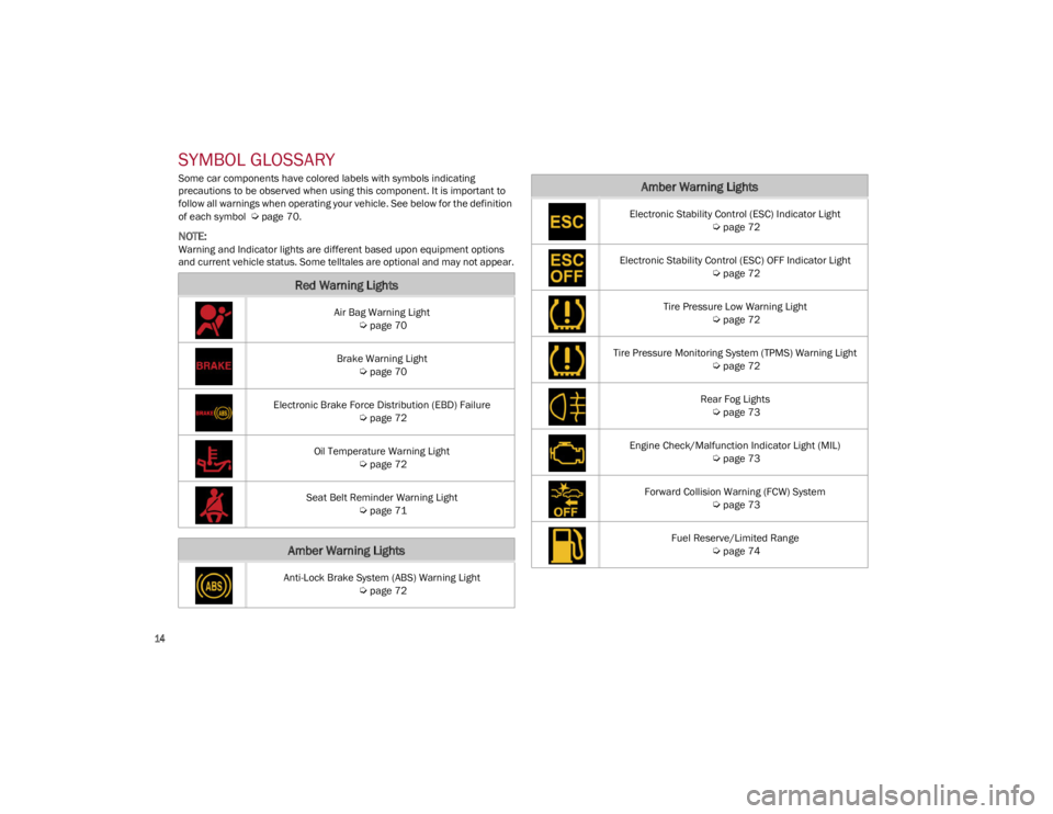
Some car components have colored labels with symbols indicating
precautions to be observed when using this component. It is important to
follow all warnings when operating your vehicle. See below for the definition
of each symbol
Ú
page 70.
NOTE:
Warning and Indicator lights are different based upon equipment options
and current vehicle status. Some telltales are optional and may not appear.
Red Warning Lights
Air Bag Warning Light
Ú
page 70
Brake Warning Light
Ú
page 70
Electronic Brake Force Distribution (EBD) Failure
Ú
page 72
Oil Temperature Warning Light
Ú
page 72
Seat Belt Reminder Warning Light
Ú
page 71
Amber Warning Lights
Anti-Lock Brake System (ABS) Warning Light
Ú
page 72
Electronic Stability Control (ESC) Indicator Light
Ú
page 72
Electronic Stability Control (ESC) OFF Indicator Light
Ú
page 72
Tire Pressure Low Warning Light
Ú
page 72
Tire Pressure Monitoring System (TPMS) Warning Light
Ú
page 72
Rear Fog Lights
Ú
page 73
Engine Check/Malfunction Indicator Light (MIL)
Ú
page 73
Forward Collision Warning (FCW) System
Ú
page 73
Fuel Reserve/Limited Range
Ú
page 74
Amber Warning Lights
22_GA_OM_EN_USC_t.book Page 14
Page 17 of 248
15
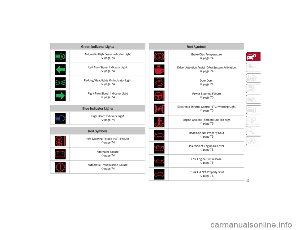
Green Indicator Lights
Automatic High Beam Indicator Light
Ú
page 74
Left Turn Signal Indicator Light
Ú
page 74
Parking/Headlights On Indicator Light
Ú
page 74
Right Turn Signal Indicator Light
Ú
page 74
Blue Indicator Lights
High Beam Indicator Light
Ú
page 74
Red Symbols
Alfa Steering Torque (AST) Failure
Ú
page 74
Alternator Failure
Ú
page 74
Automatic Transmission Failure
Ú
page 74
Brake Disc Temperature
Ú
page 74
Driver Attention Assist (DAA) System Activation
Ú
page 74
Door Open
Ú
page 74
Power Steering Failure
Ú
page 75
Electronic Throttle Control (ETC) Warning Light
Ú
page 75
Engine Coolant Temperature Too High
Ú
page 75
Hood Cap Not Properly Shut
Ú
page 75
Insufficient Engine Oil Level
Ú
page 75
Low Engine Oil Pressure
Ú
page 75
Trunk Lid Not Properly Shut
Ú
page 76
Red Symbols
22_GA_OM_EN_USC_t.book Page 15
Page 65 of 248
63
ENVIRONMENTAL
PROTECTION SYSTEMS
The following systems are used for reducing
engine emissions:
Catalytic Converter
Oxygen Sensors
Evaporation Control System
ACTIVE AERODYNAMIC
SPOILER
(QUADRIFOGLIO VEHICLES)
CARBON FIBER ACTIVE AERO FRONT
S
POILER
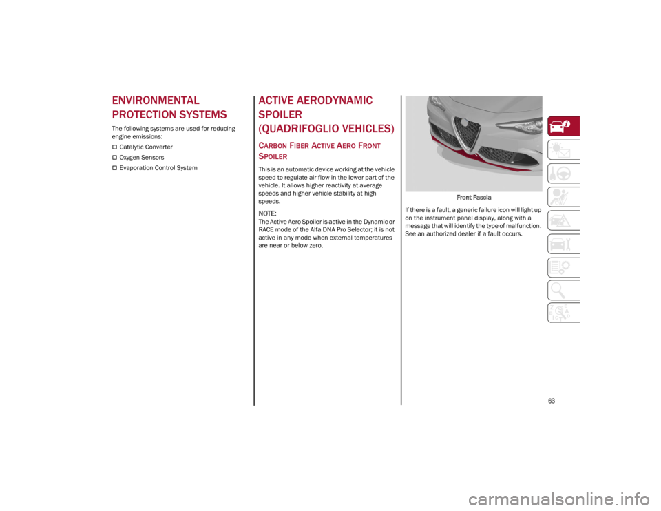
This is an automatic device working at the vehicle
speed to regulate air flow in the lower part of the
vehicle. It allows higher reactivity at average
speeds and higher vehicle stability at high
speeds.
NOTE:
The Active Aero Spoiler is active in the Dynamic or
RACE mode of the Alfa DNA Pro Selector; it is not
active in any mode when external temperatures
are near or below zero. Front Fascia
If there is a fault, a generic failure icon will light up
on the instrument panel display, along with a
message that will identify the type of malfunction.
See an authorized dealer if a fault occurs.
22_GA_OM_EN_USC_t.book Page 63
Page 67 of 248
65
Quadrifoglio Model
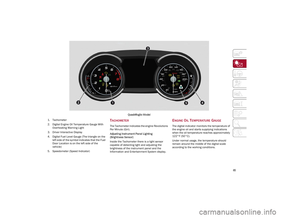
1. T
achometer
2. Digital Engine Oil Temperature Gauge With Overheating Warning Light
3. Driver Interactive Display
4. Digital Fuel Level Gauge (The triangle on the left side of the symbol indicates that the Fuel
Door Location is on the left side of the
vehicle)
5. Speedometer (Speed Indicator)
TACHOMETER
The Tachometer indicates the engine Revolutions
Per Minute (Giri).
Adjusting Instrument Panel Lighting
(Brightness Sensor)
Inside the Tachometer there is a light sensor
capable of detecting light and adjusting the
brightness of the instrument panel and the
Information and Entertainment System display.
ENGINE OIL TEMPERATURE GAUGE
The digital indicator monitors the temperature of
the engine oil and starts supplying indications
when the oil temperature reaches approximately
122°F (50°C).
Under normal usage, the temperature should
remain around the middle of the digital scale
according to the working conditions.
22_GA_OM_EN_USC_t.book Page 65
Page 68 of 248
GETTING TO KNOW YOUR INSTRUMENT PANEL
66
The Engine Oil Temperature warning light will
turn on to signal the excessive increase of the
engine oil temperature.
In the event of excessive engine oil temperature,
stop the engine immediately and contact an
authorized dealer.
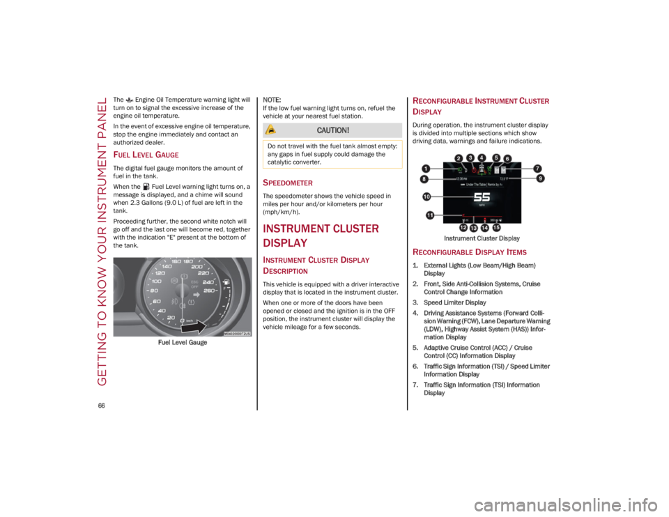
FUEL LEVEL GAUGE
The digital fuel gauge monitors the amount of
fuel in the tank.
When the Fuel Level warning light turns on, a
message is displayed, and a chime will sound
when 2.3 Gallons (9.0 L) of fuel are left in the
tank.
Proceeding further, the second white notch will
go off and the last one will become red, together
with the indication "E" present at the bottom of
the tank.Fuel Level Gauge
NOTE:
If the low fuel warning light turns on, refuel the
vehicle at your nearest fuel station.
SPEEDOMETER
The speedometer shows the vehicle speed in
miles per hour and/or kilometers per hour
(mph/km/h).
INSTRUMENT CLUSTER
DISPLAY
INSTRUMENT CLUSTER DISPLAY
D
ESCRIPTION
This vehicle is equipped with a driver interactive
display that is located in the instrument cluster.
When one or more of the doors have been
opened or closed and the ignition is in the OFF
position, the instrument cluster will display the
vehicle mileage for a few seconds.
RECONFIGURABLE INSTRUMENT CLUSTER
D
ISPLAY
During operation, the instrument cluster display
is divided into multiple sections which show
driving data, warnings and failure indications.
Instrument Cluster Display
RECONFIGURABLE DISPLAY ITEMS
1. External Lights (Low Beam/High Beam)Display
2. Front, Side Anti-Collision Systems, Cruise Control Change Information
3. Speed Limiter Display
4. Driving Assistance Systems (Forward Colli -
sion Warning (FCW), Lane Departure Warning
(LDW), Highway Assist System (HAS)) Infor -
mation Display
5. Adaptive Cruise Control (ACC) / Cruise Control (CC) Information Display
6. Traffic Sign Information (TSI) / Speed Limiter Information Display
7. Traffic Sign Information (TSI) Information Display
CAUTION!
Do not travel with the fuel tank almost empty:
any gaps in fuel supply could damage the
catalytic converter.
22_GA_OM_EN_USC_t.book Page 66
Page 74 of 248
GETTING TO KNOW YOUR INSTRUMENT PANEL
72
Electronic Brake Force Distribution (EBD)
Failure
The simultaneous turning on of the
BRAKE (red) and (amber) warning
lights with the engine on indicates
either a failure of the EBD system or
that the system is not available. In this case, the
rear wheels may suddenly lock and the vehicle
may swerve when braking abruptly.
Drive very carefully to the nearest authorized
dealer to have the system inspected
immediately.
Oil Temperature Warning Light
This telltale indicates engine oil
temperature is high.
Stop the vehicle and shut off the engine as soon
as possible. If the problem persists, contact an
authorized dealer.
AMBER WARNING LIGHTS
Anti-Lock Brake System (ABS) Warning
Light
This light monitors the ABS. The light will
turn on when the ignition is placed in
the ON/RUN position and may stay on
for as long as four seconds.
If the ABS light remains on or turns on while
driving, then the Anti-Lock portion of the brake
system is not functioning and service is required.
However, the conventional brake system will
continue to operate normally if the brake
indicator light is not on. If the ABS light is on, the brake system should be
serviced as soon as possible to restore the
benefits of Anti-Lock Brakes. If the ABS light does
not turn on when the ignition is placed in the ON/
RUN position, have the light inspected by an
authorized dealer.
Electronic Stability Control (ESC)
Indicator Light — If Equipped
When the ignition is cycled to ON, the
indicator light illuminates, but should
turn off as soon as the engine is started.
ESC System Intervention : Intervention by the
system is indicated by the flashing of the
indicator light: it indicates that the vehicle is in
critical stability and grip conditions.
ESC System Failure: If the indicator light does not
turn off, or if it stays on with the engine running,
a failure was found in the ESC system.
Hill Start Assist System Failure : The illumination
of the indicator light indicates a Hill Start Assist
system failure.
In these cases, contact an authorized dealer as
soon as possible.
Electronic Stability Control (ESC) OFF
Indicator Light — If Equipped
When the ignition is cycled to ON, the
indicator light illuminates, but should
turn off as soon as the engine is started.
The indicator light illuminates to indicate that
some active safety systems have been partially or
totally deactivated
Ú
page 129.
When the active safety systems are reactivated,
the indicator light turns off.
Tire Pressure Low Warning Light
The indicator light will illuminate to
indicate that the tire pressure is lower
than the recommended value and/or
that slow pressure loss is occurring. In
these cases, optimal tire duration and fuel
consumption may not be guaranteed.
In any situation in which the message on the
display is “See Manual”
Ú
page 142.
Tire Pressure Monitoring System (TPMS)
Warning Light
The warning light switches on and a
message is displayed to indicate that
the tire pressure is lower than the
recommended value and/or that slow
pressure loss is occurring. In these cases,
optimal tire duration and fuel consumption may
not be guaranteed.
Should one or more tires be in the condition
mentioned above, the display will show the
indications corresponding to each tire.
CAUTION!
Do not continue driving with one or more flat
tires as handling may be compromised. Stop
the vehicle, avoiding sharp braking and
steering. If a tire puncture occurs, repair
immediately using the dedicated tire repair kit
and contact an authorized dealer as soon as
possible.
22_GA_OM_EN_USC_t.book Page 72
Page 76 of 248
GETTING TO KNOW YOUR INSTRUMENT PANEL
74
Fuel Reserve/Limited Range
The indicator light (or the symbol in the
display) illuminates when about
2.4 gallons (9 liters) of fuel is left in the
tank.
GREEN INDICATOR LIGHTS
Automatic High Beam Indicator Light —
If Equipped
This indicator light will illuminate when
the automatic high beam headlights are
activated.
Left Turn Signal Indicator Light
The instrument cluster directional arrow
will flash independently for the left turn
signal as selected, as well as the
exterior turn signal lamp(s) (front and
rear) as selected when the multifunction lever is
moved down (left). This directional arrow will
flash in conjunction with the right directional
arrow when the hazard warning light button is
pushed.
Parking/Headlights On Indicator Light
This indicator will illuminate when the
parking lights or headlights are turned
on.
Right Turn Signal Indicator Light
The instrument cluster directional arrow
will flash independently for the right
turn signal as selected, as well as the
exterior turn signal lamp(s) (front and
rear) as selected when the multifunction lever is
moved up (right). This directional arrow will flash
in conjunction with the left directional arrow
when the hazard warning light button is pushed.
BLUE INDICATOR LIGHTS
High Beam Indicator Light — If Equipped
This indicator shows that the high beam
headlights are on. Push the
multifunction control lever away from
you to switch the headlights to high
beam. Push the lever a second time to switch the
headlights back to low beam. Pull the lever
toward you for a temporary high beam on, “flash
to pass” scenario.
RED SYMBOLS
Alfa Steering Torque (AST) Failure
The switching on of the telltale signals a
failure in the automatic steering
correction system.
Contact an authorized dealer to have the system
checked.
Alternator Failure
The switching on of the telltale with
engine on corresponds to an alternator
failure.
Contact an authorized dealer as soon as
possible.
Automatic Transmission Failure
The telltale turns on, together with a
buzzer warning, to indicate that the
automatic transmission is faulty.
Contact an authorized dealer as soon as
possible.
Brake Disc Temperature
When the symbol turns on, it indicates
an excessive temperature of the brake
discs. Let the breaking system cool
down by reducing the speed.
Driver Attention Assist (DAA) System
Activation
The symbol appears, together with a
message on the display, in case of
activation of the DAA system.
Stop to pause while driving, pulling the car over in
safe conditions.
Door Open
The telltale turns on when one or more
doors are not completely shut. An
acoustic signal is activated with the
doors open and the car moving.
Close the doors properly.
WARNING!
If the warning light (or the icon on the display)
flashes while driving, contact an authorized
dealer. CAUTION!
Driving the vehicle with this symbol on may
severely damage the gearbox, with resulting
breakage. The oil may also overheat: contact
with hot engine or with exhaust components at
high temperature could cause fires.
22_GA_OM_EN_USC_t.book Page 74
Page 77 of 248
75
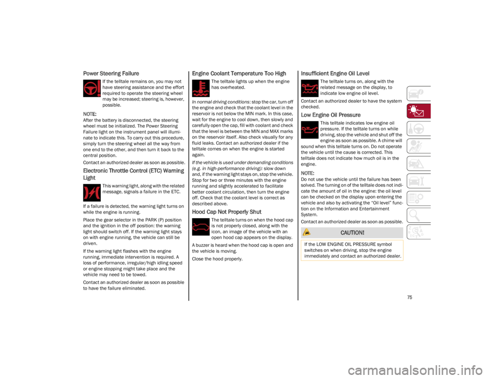
Power Steering Failure
If the telltale remains on, you may not
have steering assistance and the effort
required to operate the steering wheel
may be increased; steering is, however,
possible.
NOTE:
After the battery is disconnected, the steering
wheel must be initialized. The Power Steering
Failure light on the instrument panel will illumi-
nate to indicate this. To carry out this procedure,
simply turn the steering wheel all the way from
one end to the other, and then turn it back to the
central position.
Contact an authorized dealer as soon as possible.
Electronic Throttle Control (ETC) Warning
Light
This warning light, along with the related
message, signals a failure in the ETC.
If a failure is detected, the warning light turns on
while the engine is running.
Place the gear selector in the PARK (P) position
and the ignition in the off position: the warning
light should switch off. If the warning light stays
on with engine running, the vehicle can still be
driven.
If the warning light flashes with the engine
running, immediate intervention is required. A
loss of performance, irregular/high idling speed
or engine stopping might take place and the
vehicle may need to be towed.
Contact an authorized dealer as soon as possible
to have the failure eliminated.
Engine Coolant Temperature Too High
The telltale lights up when the engine
has overheated.
In normal driving conditions : stop the car, turn off
the engine and check that the coolant level in the
reservoir is not below the MIN mark. In this case,
wait for the engine to cool down, then slowly and
carefully open the cap, fill with coolant and check
that the level is between the MIN and MAX marks
on the reservoir itself. Also check visually for any
fluid leaks. Contact an authorized dealer if the
telltale comes on when the engine is started
again.
If the vehicle is used under demanding conditions
(e.g. in high-performance driving): slow down
and, if the warning light stays on, stop the vehicle.
Stop for two or three minutes with the engine
running and slightly accelerated to facilitate
better coolant circulation, then turn the engine
off. Check that the coolant level is correct as
described above.
Hood Cap Not Properly Shut
The telltale turns on when the hood cap
is not properly closed, along with the
icon, an image of the vehicle with an
open hood cap appears on the display.
A buzzer is heard when the hood cap is open and
the vehicle is moving.
Close the hood properly.
Insufficient Engine Oil Level
The telltale turns on, along with the
related message on the display, to
indicate low engine oil level.
Contact an authorized dealer to have the system
checked.
Low Engine Oil Pressure
This telltale indicates low engine oil
pressure. If the telltale turns on while
driving, stop the vehicle and shut off the
engine as soon as possible. A chime will
sound when this telltale turns on. Do not operate
the vehicle until the cause is corrected. This
telltale does not indicate how much oil is in the
engine.
NOTE:
Do not use the vehicle until the failure has been
solved. The turning on of the telltale does not indi -
cate the amount of oil in the engine: the oil level
can be checked on the display upon entering the
vehicle and also by activating the “Oil level” func -
tion on the Information and Entertainment
System.
Contact an authorized dealer as soon as possible.
CAUTION!
If the LOW ENGINE OIL PRESSURE symbol
switches on when driving, stop the engine
immediately and contact an authorized dealer.
22_GA_OM_EN_USC_t.book Page 75