warning lights ALFA ROMEO GIULIA 2022 Owners Manual
[x] Cancel search | Manufacturer: ALFA ROMEO, Model Year: 2022, Model line: GIULIA, Model: ALFA ROMEO GIULIA 2022Pages: 248, PDF Size: 9.71 MB
Page 11 of 248
9
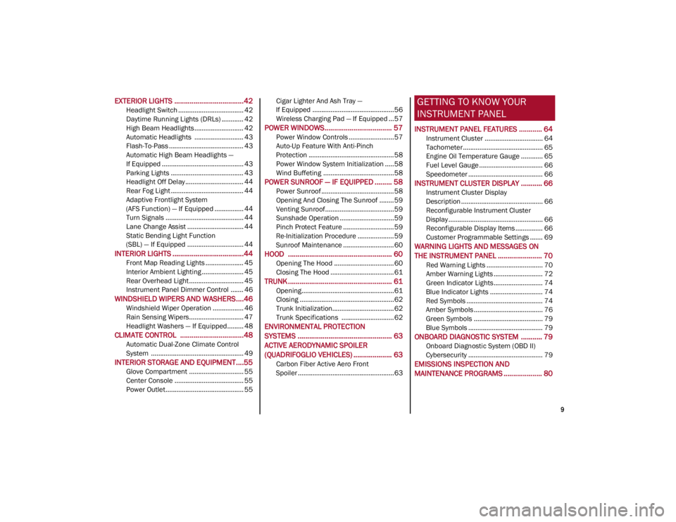
EXTERIOR LIGHTS ....................................42
Headlight Switch .................................... 42
Daytime Running Lights (DRLs) ............ 42
High Beam Headlights ........................... 42
Automatic Headlights ........................... 43
Flash-To-Pass ......................................... 43
Automatic High Beam Headlights —
If Equipped ............................................. 43 Parking Lights ........................................ 43
Headlight Off Delay ................................ 44
Rear Fog Light ........................................ 44
Adaptive Frontlight System
(AFS Function) — If Equipped ................ 44 Turn Signals ........................................... 44
Lane Change Assist ............................... 44
Static Bending Light Function
(SBL) — If Equipped ............................... 44
INTERIOR LIGHTS .....................................44
Front Map Reading Lights ..................... 45
Interior Ambient Lighting ....................... 45
Rear Overhead Light .............................. 45
Instrument Panel Dimmer Control ....... 46
WINDSHIELD WIPERS AND WASHERS....46
Windshield Wiper Operation ................. 46
Rain Sensing Wipers.............................. 47
Headlight Washers — If Equipped......... 48
CLIMATE CONTROL .................................48
Automatic Dual-Zone Climate Control
System ................................................... 49
INTERIOR STORAGE AND EQUIPMENT....55
Glove Compartment .............................. 55
Center Console ...................................... 55
Power Outlet........................................... 55 Cigar Lighter And Ash Tray —
If Equipped .............................................56 Wireless Charging Pad — If Equipped ...57
POWER WINDOWS................................... 57
Power Window Controls .........................57
Auto-Up Feature With Anti-Pinch
Protection ............................................... 58 Power Window System Initialization .....58
Wind Buffeting .......................................58
POWER SUNROOF — IF EQUIPPED ......... 58
Power Sunroof ........................................ 58
Opening And Closing The Sunroof ........59
Venting Sunroof......................................59
Sunshade Operation ..............................59
Pinch Protect Feature ............................59
Re-Initialization Procedure ....................59
Sunroof Maintenance ............................60
HOOD ...................................................... 60
Opening The Hood ................................. 60
Closing The Hood ...................................61
TRUNK ...................................................... 61
Opening...................................................61
Closing ....................................................62
Trunk Initialization..................................62
Trunk Specifications .............................62
ENVIRONMENTAL PROTECTION
SYSTEMS ................................................. 63
ACTIVE AERODYNAMIC SPOILER
(QUADRIFOGLIO VEHICLES) .................... 63
Carbon Fiber Active Aero Front
Spoiler .....................................................63
GETTING TO KNOW YOUR
INSTRUMENT PANEL
INSTRUMENT PANEL FEATURES ............ 64
Instrument Cluster ................................ 64
Tachometer............................................ 65
Engine Oil Temperature Gauge ............ 65
Fuel Level Gauge ................................... 66
Speedometer ......................................... 66
INSTRUMENT CLUSTER DISPLAY ........... 66
Instrument Cluster Display
Description ............................................. 66 Reconfigurable Instrument Cluster
Display .................................................... 66 Reconfigurable Display Items ............... 66
Customer Programmable Settings ....... 69
WARNING LIGHTS AND MESSAGES ON
THE INSTRUMENT PANEL ....................... 70
Red Warning Lights ............................... 70
Amber Warning Lights ........................... 72
Green Indicator Lights........................... 74
Blue Indicator Lights ............................. 74
Red Symbols .......................................... 74
Amber Symbols ...................................... 76
Green Symbols ...................................... 79
Blue Symbols ......................................... 79
ONBOARD DIAGNOSTIC SYSTEM ........... 79
Onboard Diagnostic System (OBD II)
Cybersecurity ......................................... 79
EMISSIONS INSPECTION AND
MAINTENANCE PROGRAMS .................... 80
22_GA_OM_EN_USC_t.book Page 9
Page 16 of 248
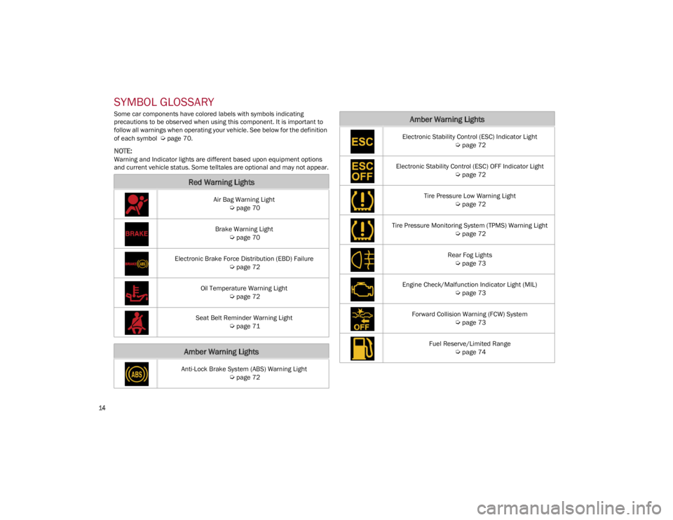
SYMBOL GLOSSARY
14
SYMBOL GLOSSARY
Some car components have colored labels with symbols indicating
precautions to be observed when using this component. It is important to
follow all warnings when operating your vehicle. See below for the definition
of each symbol
Ú
page 70.
NOTE:
Warning and Indicator lights are different based upon equipment options
and current vehicle status. Some telltales are optional and may not appear.
Red Warning Lights
Air Bag Warning Light
Ú
page 70
Brake Warning Light
Ú
page 70
Electronic Brake Force Distribution (EBD) Failure
Ú
page 72
Oil Temperature Warning Light
Ú
page 72
Seat Belt Reminder Warning Light
Ú
page 71
Amber Warning Lights
Anti-Lock Brake System (ABS) Warning Light
Ú
page 72
Electronic Stability Control (ESC) Indicator Light
Ú
page 72
Electronic Stability Control (ESC) OFF Indicator Light
Ú
page 72
Tire Pressure Low Warning Light
Ú
page 72
Tire Pressure Monitoring System (TPMS) Warning Light
Ú
page 72
Rear Fog Lights
Ú
page 73
Engine Check/Malfunction Indicator Light (MIL)
Ú
page 73
Forward Collision Warning (FCW) System
Ú
page 73
Fuel Reserve/Limited Range
Ú
page 74
Amber Warning Lights
22_GA_OM_EN_USC_t.book Page 14
Page 17 of 248
15
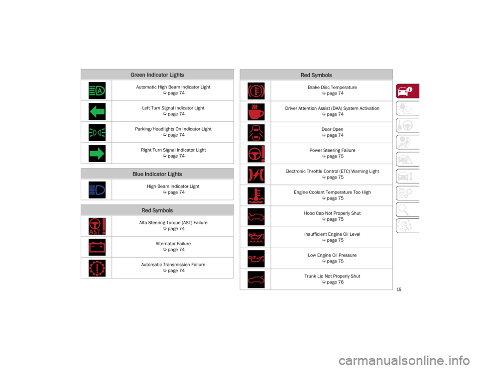
Green Indicator Lights
Automatic High Beam Indicator Light
Ú
page 74
Left Turn Signal Indicator Light
Ú
page 74
Parking/Headlights On Indicator Light
Ú
page 74
Right Turn Signal Indicator Light
Ú
page 74
Blue Indicator Lights
High Beam Indicator Light
Ú
page 74
Red Symbols
Alfa Steering Torque (AST) Failure
Ú
page 74
Alternator Failure
Ú
page 74
Automatic Transmission Failure
Ú
page 74
Brake Disc Temperature
Ú
page 74
Driver Attention Assist (DAA) System Activation
Ú
page 74
Door Open
Ú
page 74
Power Steering Failure
Ú
page 75
Electronic Throttle Control (ETC) Warning Light
Ú
page 75
Engine Coolant Temperature Too High
Ú
page 75
Hood Cap Not Properly Shut
Ú
page 75
Insufficient Engine Oil Level
Ú
page 75
Low Engine Oil Pressure
Ú
page 75
Trunk Lid Not Properly Shut
Ú
page 76
Red Symbols
22_GA_OM_EN_USC_t.book Page 15
Page 18 of 248
SYMBOL GLOSSARY
16
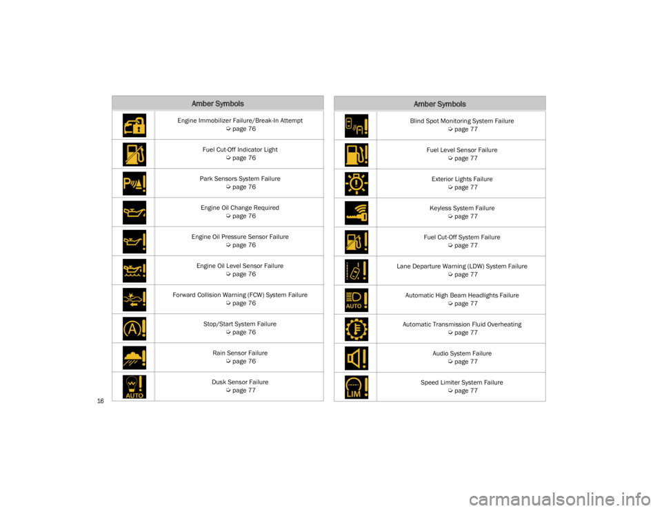
Amber Symbols
Engine Immobilizer Failure/Break-In Attempt
Ú
page 76
Fuel Cut-Off Indicator Light
Ú
page 76
Park Sensors System Failure
Ú
page 76
Engine Oil Change Required
Ú
page 76
Engine Oil Pressure Sensor Failure
Ú
page 76
Engine Oil Level Sensor Failure
Ú
page 76
Forward Collision Warning (FCW) System Failure
Ú
page 76
Stop/Start System Failure
Ú
page 76
Rain Sensor Failure
Ú
page 76
Dusk Sensor Failure
Ú
page 77
Blind Spot Monitoring System Failure
Ú
page 77
Fuel Level Sensor Failure
Ú
page 77
Exterior Lights Failure
Ú
page 77
Keyless System Failure
Ú
page 77
Fuel Cut-Off System Failure
Ú
page 77
Lane Departure Warning (LDW) System Failure
Ú
page 77
Automatic High Beam Headlights Failure
Ú
page 77
Automatic Transmission Fluid Overheating
Ú
page 77
Audio System Failure
Ú
page 77
Speed Limiter System Failure
Ú
page 77
Amber Symbols
22_GA_OM_EN_USC_t.book Page 16
Page 39 of 248
37
Head Restraint Removal
To remove adjustable head restraints, proceed as
follows:
1. Raise the head restraints to their maximum height.
2. Push the adjustment button and the release button at the side of the two supports.
3. Remove the head restraints by pulling them upwards.
To reinstall the head restraints, proceed as
follows:
1. Hold down both the adjustment button and release button while placing the head
restraint post into the holes.
2. Then, reposition the head restraint to the appropriate height for the passengers.MIRRORS
AUTOMATIC DIMMING MIRROR
The rearview mirror can be adjusted up, down,
left, and right. The mirror should be adjusted to
center on the view through the rear window.
This mirror automatically adjusts for headlight
glare from vehicles behind you.
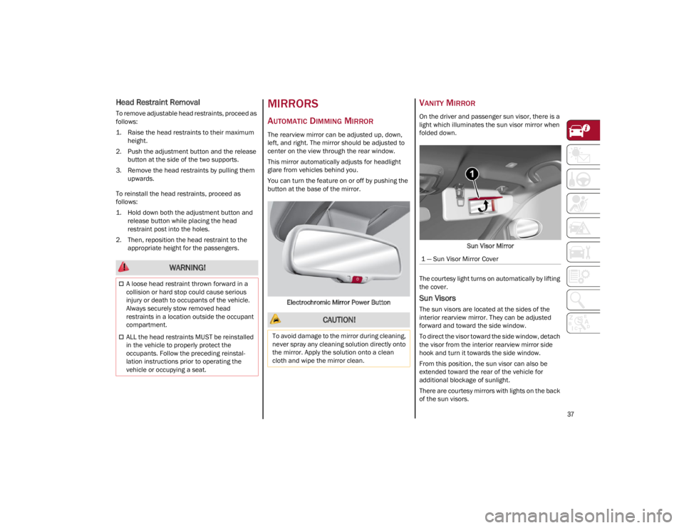
You can turn the feature on or off by pushing the
button at the base of the mirror.
Electrochromic Mirror Power Button
VANITY MIRROR
On the driver and passenger sun visor, there is a
light which illuminates the sun visor mirror when
folded down. Sun Visor Mirror
The courtesy light turns on automatically by lifting
the cover.
Sun Visors
The sun visors are located at the sides of the
interior rearview mirror. They can be adjusted
forward and toward the side window.
To direct the visor toward the side window, detach
the visor from the interior rearview mirror side
hook and turn it towards the side window.
From this position, the sun visor can also be
extended toward the rear of the vehicle for
additional blockage of sunlight.
There are courtesy mirrors with lights on the back
of the sun visors.
WARNING!
A loose head restraint thrown forward in a
collision or hard stop could cause serious
injury or death to occupants of the vehicle.
Always securely stow removed head
restraints in a location outside the occupant
compartment.
ALL the head restraints MUST be reinstalled
in the vehicle to properly protect the
occupants. Follow the preceding reinstal -
lation instructions prior to operating the
vehicle or occupying a seat.
CAUTION!
To avoid damage to the mirror during cleaning,
never spray any cleaning solution directly onto
the mirror. Apply the solution onto a clean
cloth and wipe the mirror clean.
1 — Sun Visor Mirror Cover
22_GA_OM_EN_USC_t.book Page 37
Page 44 of 248
GETTING TO KNOW YOUR VEHICLE
42
If you have any problems, or require assistance,
please call toll-free 1-800-355-3515 or, on the
Internet at
HomeLink.com
for information or
assistance.
EXTERIOR LIGHTS
HEADLIGHT SWITCH
The headlight switch is located on the left side of
the instrument panel, next to the steering wheel.
The headlight switch controls the operation of the
headlights, parking lights, instrument panel
lights, instrument panel light dimming, interior
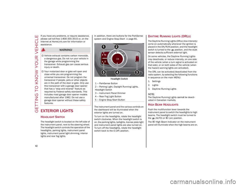
lights and rear fog lights. In addition, there are buttons for the ParkSense
system and Engine Stop/Start
Ú
page 81.
Headlight Switch
The instrument panel and the various controls on
the dashboard will be illuminated when the
exterior lights are turned on.
To turn on the headlights, rotate the headlight
switch clockwise. When the headlight switch is
on, the parking lights, taillights, license plate light
and instrument panel lights are also turned on.
To turn off the headlights, rotate the headlight
switch back to the O (off) position.DAYTIME RUNNING LIGHTS (DRLS)
The Daytime Running Lights (DRLs) (low intensity)
come on automatically whenever the ignition is
placed in the ON/RUN position, and the headlight
switch is turned to the position, and the dusk
sensor detects sufficient external light.
On some vehicles, the Daytime Running Lights
may deactivate, or reduce intensity, on one side
of the vehicle (when a turn signal is activated on
that side), or on both sides of the vehicle (when
the hazard warning lights are activated).
The DRL can be activated/deactivated from the
radio system, by selecting the following functions
in sequence on the main MENU:
1. Settings
2. Lights
3. Daytime Running Lights
NOTE:
The Daytime Running Lights cannot be deacti -
vated in Canadian markets.
HIGH BEAM HEADLIGHTS
Push the multifunction lever towards the
instrument panel to switch the headlights to high
beams. The headlight switch must be turned to
the (AUTO) or (on) position.
The High Beam Indicator on the instrument
panel will illuminate when the high beams are on.
WARNING!
Vehicle exhaust contains carbon monoxide,
a dangerous gas. Do not run your vehicle in
the garage while programming the
transceiver. Exhaust gas can cause serious
injury or death.
Your motorized door or gate will open and
close while you are programming the
universal transceiver. Do not program the
transceiver if people, pets or other objects
are in the path of the door or gate. Only use
this transceiver with a garage door opener
that has a “stop and reverse” feature as
required by Federal safety standards. This
includes most garage door opener models
manufactured after 1982. Do not use a
garage door opener without these safety
features.
1 — ParkSense Button
2 — Parking Light, Daylight Running Lights,
Headlight Switch
3 — Instrument Panel Dimmer
4 — Rear Fog Light Button
5 — Engine Stop/Start Button
22_GA_OM_EN_USC_t.book Page 42
Page 45 of 248
43
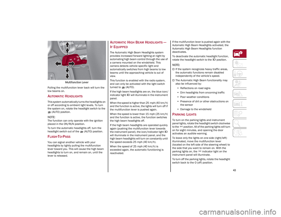
Multifunction Lever
Pulling the multifunction lever back will turn the
low beams on.
AUTOMATIC HEADLIGHTS
This system automatically turns the headlights on
or off according to ambient light levels. To turn
the system on, rotate the headlight switch to the (AUTO) position.
NOTE:
The function can only operate with the ignition
placed in the ON/RUN position.
To turn the automatic headlights off, turn the
headlight switch out of the (AUTO) position.
FLASH-TO-PASS
You can signal another vehicle with your
headlights by lightly pulling the multifunction
lever toward you. This will cause the high beam
headlights to turn on, and remain on, until the
lever is released.
AUTOMATIC HIGH BEAM HEADLIGHTS —
I
F EQUIPPED
The Automatic High Beam Headlights system
provides increased forward lighting at night by
automating high beam control through the use of
a camera mounted on the windshield. This
camera detects vehicle specific light and
automatically switches from high beams to low
beams until the approaching vehicle is out of
view.
This function is enabled with the radio system,
and can only be activated with the light switch
turned to (AUTO).
If the high beam headlights are on, the blue icon/
indicator light will illuminate in the instrument
panel.
When the speed is higher than 25 mph (40 km/h)
and the function is active, the lights will turn off if
the multifunction lever is pushed again.
When the speed is lower than 15 mph (25 km/h)
and the function is active, the function switches
the high beam headlights off.
If the high beam headlights are operated quickly
again (pushing the multifunction lever towards
the instrument panel), the icon/indicator light
will illuminate in the instrument panel, and the
high beam headlights will turn on constantly until
the speed exceeds 25 mph (40 km/h).
When the speed of 25 mph (40 km/h) is
exceeded again, the automatic functioning is
reactivated. If the multifunction lever is pushed again with the
Automatic High Beam Headlights activated, the
Automatic High Beam Headlights function
deactivates.
To deactivate the automatic headlight function,
rotate the headlight switch to the position.
NOTE:
If the system recognizes heavy traffic areas,
the automatic functions remain disabled
independently of the vehicle’s speed.
The Automatic High Beam functionality may
also be influenced by:
• Reflections on road signs
• Dim headlights from oncoming traffic
• Poor weather conditions
• Presence of dirt or other obstructions on
the sensor
• Damage to the windshield
PARKING LIGHTS
To turn on the parking lights and instrument
panel lights, rotate the headlight switch clockwise
to the position. All of the parking lights will turn
on for eight minutes, and opening the door
activates an audible warning.
To leave only the lights on one side (right/left)
illuminated, move the multifunction lever
(located on the left side of the steering wheel) to
the side that you want to remain on. With the
parking lights on, the indicator light on the
instrument panel will illuminate.
To turn off the parking lights, rotate the headlight
switch back to the O (off) position.
22_GA_OM_EN_USC_t.book Page 43
Page 58 of 248
GETTING TO KNOW YOUR VEHICLE
56
(Continued)
NOTE:
All accessories connected to powered outlets
should be removed or turned off when the vehicle
is not in use to protect the battery against
discharge.
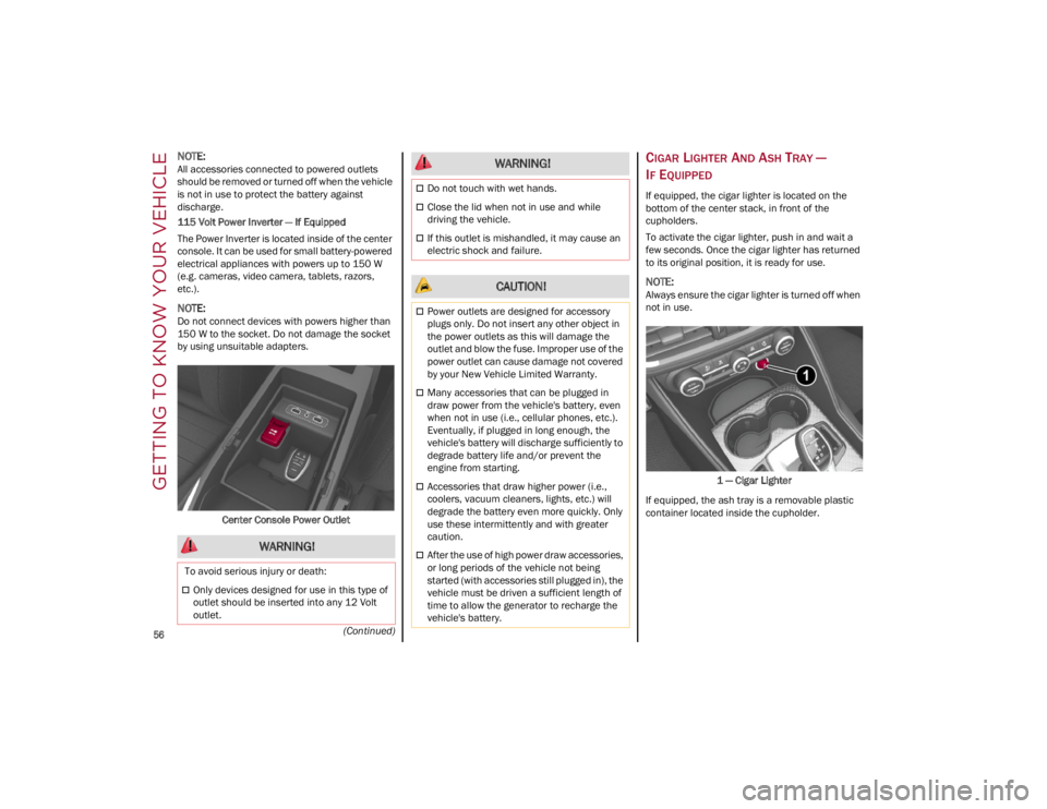
115 Volt Power Inverter — If Equipped
The Power Inverter is located inside of the center
console. It can be used for small battery-powered
electrical appliances with powers up to 150 W
(e.g. cameras, video camera, tablets, razors,
etc.).
NOTE:
Do not connect devices with powers higher than
150 W to the socket. Do not damage the socket
by using unsuitable adapters.Center Console Power Outlet
CIGAR LIGHTER AND ASH TRAY —
I
F EQUIPPED
If equipped, the cigar lighter is located on the
bottom of the center stack, in front of the
cupholders.
To activate the cigar lighter, push in and wait a
few seconds. Once the cigar lighter has returned
to its original position, it is ready for use.
NOTE:
Always ensure the cigar lighter is turned off when
not in use.
1 — Cigar Lighter
If equipped, the ash tray is a removable plastic
container located inside the cupholder.
WARNING!
To avoid serious injury or death:
Only devices designed for use in this type of
outlet should be inserted into any 12 Volt
outlet.
Do not touch with wet hands.
Close the lid when not in use and while
driving the vehicle.
If this outlet is mishandled, it may cause an
electric shock and failure.
CAUTION!
Power outlets are designed for accessory
plugs only. Do not insert any other object in
the power outlets as this will damage the
outlet and blow the fuse. Improper use of the
power outlet can cause damage not covered
by your New Vehicle Limited Warranty.
Many accessories that can be plugged in
draw power from the vehicle's battery, even
when not in use (i.e., cellular phones, etc.).
Eventually, if plugged in long enough, the
vehicle's battery will discharge sufficiently to
degrade battery life and/or prevent the
engine from starting.
Accessories that draw higher power (i.e.,
coolers, vacuum cleaners, lights, etc.) will
degrade the battery even more quickly. Only
use these intermittently and with greater
caution.
After the use of high power draw accessories,
or long periods of the vehicle not being
started (with accessories still plugged in), the
vehicle must be driven a sufficient length of
time to allow the generator to recharge the
vehicle's battery.
WARNING!
22_GA_OM_EN_USC_t.book Page 56
Page 63 of 248
61
CLOSING THE HOOD
To close, lower the hood to approximately
16 inches (40 cm) from the engine compartment
then let it drop. Make sure that the hood is
completely closed and fully latched.
NOTE:
Since the hood is equipped with a double locking
system, one for each side, check that it is closed
on both its side ends.
TRUNK
The trunk unlocking is electrically operated and is
deactivated when the vehicle is in motion.
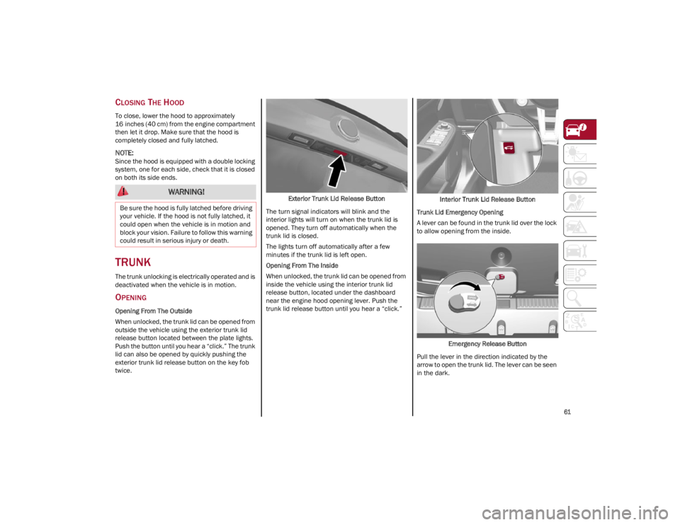
OPENING
Opening From The Outside
When unlocked, the trunk lid can be opened from
outside the vehicle using the exterior trunk lid
release button located between the plate lights.
Push the button until you hear a “click.” The trunk
lid can also be opened by quickly pushing the
exterior trunk lid release button on the key fob
twice.Exterior Trunk Lid Release Button
The turn signal indicators will blink and the
interior lights will turn on when the trunk lid is
opened. They turn off automatically when the
trunk lid is closed.
The lights turn off automatically after a few
minutes if the trunk lid is left open.
Opening From The Inside
When unlocked, the trunk lid can be opened from
inside the vehicle using the interior trunk lid
release button, located under the dashboard
near the engine hood opening lever. Push the
trunk lid release button until you hear a “click.” Interior Trunk Lid Release Button
Trunk Lid Emergency Opening
A lever can be found in the trunk lid over the lock
to allow opening from the inside.
Emergency Release Button
Pull the lever in the direction indicated by the
arrow to open the trunk lid. The lever can be seen
in the dark.
WARNING!
Be sure the hood is fully latched before driving
your vehicle. If the hood is not fully latched, it
could open when the vehicle is in motion and
block your vision. Failure to follow this warning
could result in serious injury or death.
22_GA_OM_EN_USC_t.book Page 61
Page 68 of 248
GETTING TO KNOW YOUR INSTRUMENT PANEL
66
The Engine Oil Temperature warning light will
turn on to signal the excessive increase of the
engine oil temperature.
In the event of excessive engine oil temperature,
stop the engine immediately and contact an
authorized dealer.
FUEL LEVEL GAUGE
The digital fuel gauge monitors the amount of
fuel in the tank.
When the Fuel Level warning light turns on, a
message is displayed, and a chime will sound
when 2.3 Gallons (9.0 L) of fuel are left in the
tank.
Proceeding further, the second white notch will
go off and the last one will become red, together
with the indication "E" present at the bottom of
the tank.Fuel Level Gauge
NOTE:
If the low fuel warning light turns on, refuel the
vehicle at your nearest fuel station.
SPEEDOMETER
The speedometer shows the vehicle speed in
miles per hour and/or kilometers per hour
(mph/km/h).
INSTRUMENT CLUSTER
DISPLAY
INSTRUMENT CLUSTER DISPLAY
D
ESCRIPTION
This vehicle is equipped with a driver interactive
display that is located in the instrument cluster.
When one or more of the doors have been
opened or closed and the ignition is in the OFF
position, the instrument cluster will display the
vehicle mileage for a few seconds.
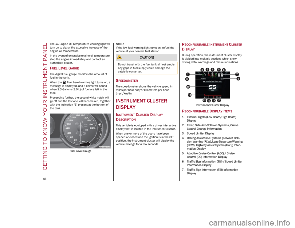
RECONFIGURABLE INSTRUMENT CLUSTER
D
ISPLAY
During operation, the instrument cluster display
is divided into multiple sections which show
driving data, warnings and failure indications.
Instrument Cluster Display
RECONFIGURABLE DISPLAY ITEMS
1. External Lights (Low Beam/High Beam)Display
2. Front, Side Anti-Collision Systems, Cruise Control Change Information
3. Speed Limiter Display
4. Driving Assistance Systems (Forward Colli -
sion Warning (FCW), Lane Departure Warning
(LDW), Highway Assist System (HAS)) Infor -
mation Display
5. Adaptive Cruise Control (ACC) / Cruise Control (CC) Information Display
6. Traffic Sign Information (TSI) / Speed Limiter Information Display
7. Traffic Sign Information (TSI) Information Display
CAUTION!
Do not travel with the fuel tank almost empty:
any gaps in fuel supply could damage the
catalytic converter.
22_GA_OM_EN_USC_t.book Page 66