brake light ALFA ROMEO GIULIA 2023 Owners Manual
[x] Cancel search | Manufacturer: ALFA ROMEO, Model Year: 2023, Model line: GIULIA, Model: ALFA ROMEO GIULIA 2023Pages: 248, PDF Size: 9.62 MB
Page 14 of 248
12
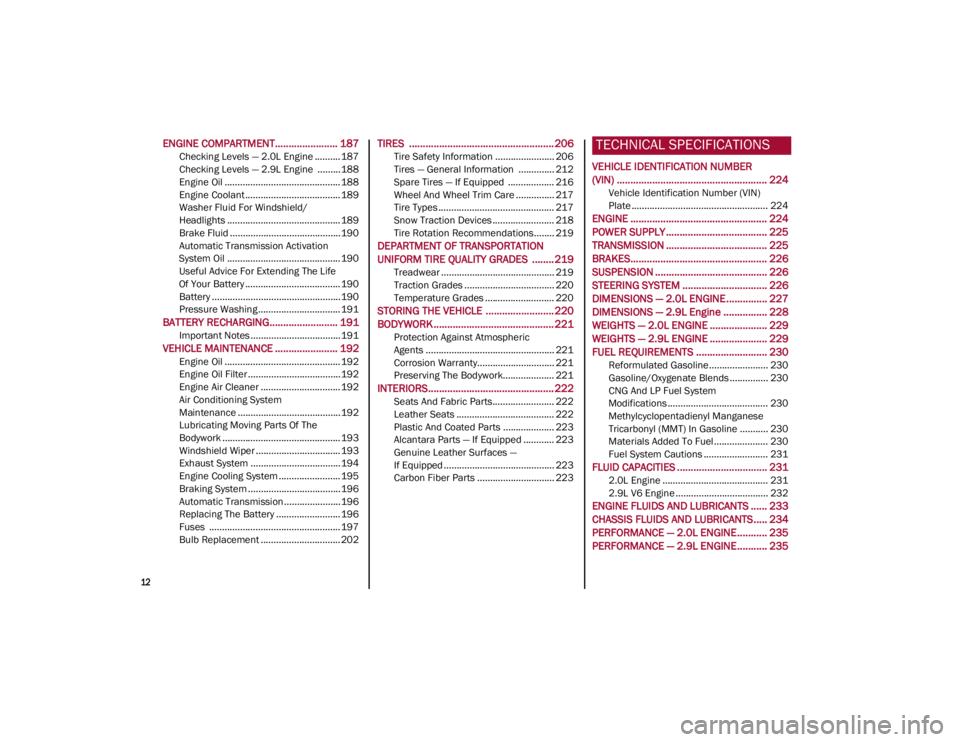
ENGINE COMPARTMENT....................... 187
Checking Levels — 2.0L Engine .......... 187
Checking Levels — 2.9L Engine .........188
Engine Oil ............................................. 188
Engine Coolant ..................................... 189
Washer Fluid For Windshield/
Headlights ............................................ 189 Brake Fluid ...........................................190
Automatic Transmission Activation
System Oil ............................................ 190 Useful Advice For Extending The Life
Of Your Battery ..................................... 190 Battery ..................................................190
Pressure Washing ................................ 191
BATTERY RECHARGING......................... 191
Important Notes ...................................191
VEHICLE MAINTENANCE ....................... 192
Engine Oil ............................................. 192
Engine Oil Filter ....................................192
Engine Air Cleaner ............................... 192
Air Conditioning System
Maintenance ........................................192 Lubricating Moving Parts Of The
Bodywork ..............................................193 Windshield Wiper .................................193
Exhaust System ...................................194
Engine Cooling System ........................ 195
Braking System ....................................196
Automatic Transmission ......................196
Replacing The Battery ......................... 196
Fuses ................................................... 197
Bulb Replacement ............................... 202
TIRES ..................................................... 206
Tire Safety Information ....................... 206
Tires — General Information .............. 212
Spare Tires — If Equipped .................. 216
Wheel And Wheel Trim Care ............... 217
Tire Types ............................................. 217
Snow Traction Devices ........................ 218
Tire Rotation Recommendations........ 219
DEPARTMENT OF TRANSPORTATION
UNIFORM TIRE QUALITY GRADES ........ 219
Treadwear ............................................ 219
Traction Grades ................................... 220
Temperature Grades ........................... 220
STORING THE VEHICLE ......................... 220
BODYWORK ............................................ 221
Protection Against Atmospheric
Agents .................................................. 221 Corrosion Warranty.............................. 221
Preserving The Bodywork.................... 221
INTERIORS.............................................. 222
Seats And Fabric Parts........................ 222
Leather Seats ...................................... 222
Plastic And Coated Parts .................... 223
Alcantara Parts — If Equipped ............ 223
Genuine Leather Surfaces —
If Equipped ........................................... 223 Carbon Fiber Parts .............................. 223
TECHNICAL SPECIFICATIONS
VEHICLE IDENTIFICATION NUMBER
(VIN) ....................................................... 224
Vehicle Identification Number (VIN)
Plate ..................................................... 224
ENGINE .................................................. 224
POWER SUPPLY ..................................... 225 TRANSMISSION ..................................... 225BRAKES.................................................. 226
SUSPENSION ......................................... 226
STEERING SYSTEM ............................... 226DIMENSIONS — 2.0L ENGINE ............... 227
DIMENSIONS — 2.9L Engine ................ 228
WEIGHTS — 2.0L ENGINE ..................... 229
WEIGHTS — 2.9L ENGINE ..................... 229
FUEL REQUIREMENTS .......................... 230
Reformulated Gasoline....................... 230
Gasoline/Oxygenate Blends ............... 230
CNG And LP Fuel System
Modifications ....................................... 230 Methylcyclopentadienyl Manganese
Tricarbonyl (MMT) In Gasoline ........... 230 Materials Added To Fuel ..................... 230
Fuel System Cautions ......................... 231
FLUID CAPACITIES ................................. 231
2.0L Engine ......................................... 231
2.9L V6 Engine .................................... 232
ENGINE FLUIDS AND LUBRICANTS ...... 233
CHASSIS FLUIDS AND LUBRICANTS..... 234 PERFORMANCE — 2.0L ENGINE........... 235PERFORMANCE — 2.9L ENGINE........... 235
23_GA_OM_EN_USC_t.book Page 12
Page 16 of 248
SYMBOL GLOSSARY
14
SYMBOL GLOSSARY
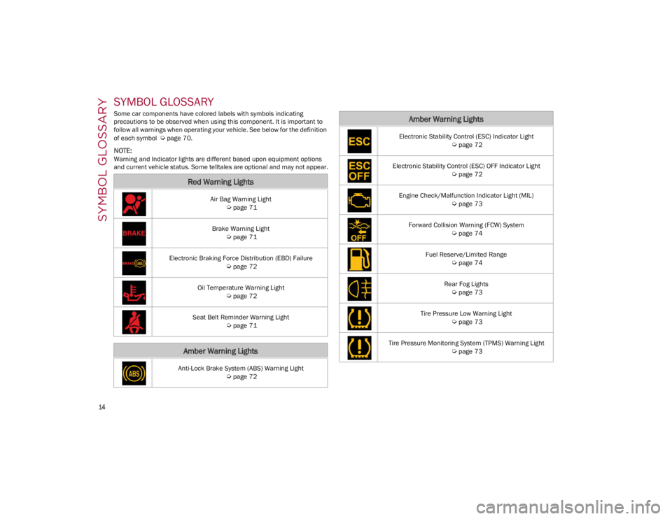
Some car components have colored labels with symbols indicating
precautions to be observed when using this component. It is important to
follow all warnings when operating your vehicle. See below for the definition
of each symbol
Ú
page 70.
NOTE:
Warning and Indicator lights are different based upon equipment options
and current vehicle status. Some telltales are optional and may not appear.
Red Warning Lights
Air Bag Warning Light
Ú
page 71
Brake Warning Light
Ú
page 71
Electronic Braking Force Distribution (EBD) Failure
Ú
page 72
Oil Temperature Warning Light
Ú
page 72
Seat Belt Reminder Warning Light
Ú
page 71
Amber Warning Lights
Anti-Lock Brake System (ABS) Warning Light
Ú
page 72
Electronic Stability Control (ESC) Indicator Light
Ú
page 72
Electronic Stability Control (ESC) OFF Indicator Light
Ú
page 72
Engine Check/Malfunction Indicator Light (MIL)
Ú
page 73
Forward Collision Warning (FCW) System
Ú
page 74
Fuel Reserve/Limited Range
Ú
page 74
Rear Fog Lights
Ú
page 73
Tire Pressure Low Warning Light
Ú
page 73
Tire Pressure Monitoring System (TPMS) Warning Light
Ú
page 73
Amber Warning Lights
23_GA_OM_EN_USC_t.book Page 14
Page 17 of 248
15
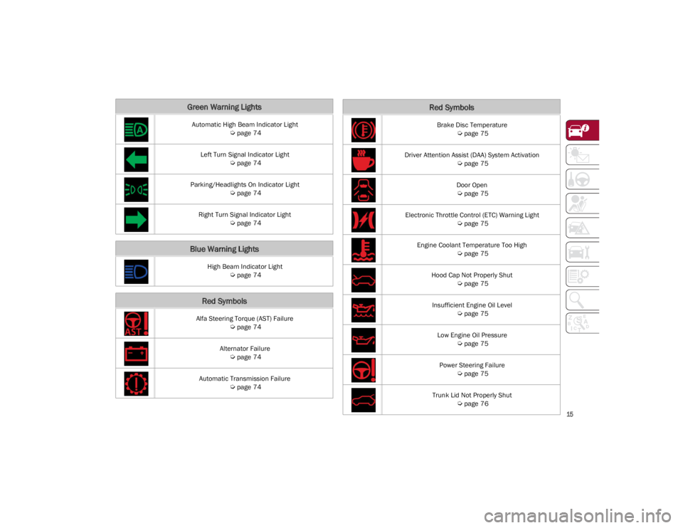
Green Warning Lights
Automatic High Beam Indicator Light
Ú
page 74
Left Turn Signal Indicator Light
Ú
page 74
Parking/Headlights On Indicator Light
Ú
page 74
Right Turn Signal Indicator Light
Ú
page 74
Blue Warning Lights
High Beam Indicator Light
Ú
page 74
Red Symbols
Alfa Steering Torque (AST) Failure
Ú
page 74
Alternator Failure
Ú
page 74
Automatic Transmission Failure
Ú
page 74
Brake Disc Temperature
Ú
page 75
Driver Attention Assist (DAA) System Activation
Ú
page 75
Door Open
Ú
page 75
Electronic Throttle Control (ETC) Warning Light
Ú
page 75
Engine Coolant Temperature Too High
Ú
page 75
Hood Cap Not Properly Shut
Ú
page 75
Insufficient Engine Oil Level
Ú
page 75
Low Engine Oil Pressure
Ú
page 75
Power Steering Failure
Ú
page 75
Trunk Lid Not Properly Shut
Ú
page 76
Red Symbols
23_GA_OM_EN_USC_t.book Page 15
Page 18 of 248
SYMBOL GLOSSARY
16
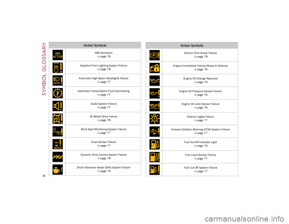
Amber Symbols
ABS Activation
Ú
page 78
Adaptive Front Lighting System Failure
Ú
page 78
Automatic High Beam Headlights Failure
Ú
page 77
Automatic Transmission Fluid Overheating
Ú
page 77
Audio System Failure
Ú
page 77
All Wheel Drive Failure
Ú
page 78
Blind Spot Monitoring System Failure
Ú
page 77
Dusk Sensor Failure
Ú
page 77
Dynamic Drive Control System Failure
Ú
page 78
Driver Attention Assist (DAA) System Failure
Ú
page 79
Electric Park Brake Failure
Ú
page 78
Engine Immobilizer Failure/Break-In Attempt
Ú
page 76
Engine Oil Change Required
Ú
page 76
Engine Oil Pressure Sensor Failure
Ú
page 76
Engine Oil Level Sensor Failure
Ú
page 76
Exterior Lights Failure
Ú
page 77
Forward Collision Warning (FCW) System Failure
Ú
page 77
Fuel Cut-Off Indicator Light
Ú
page 76
Fuel Level Sensor Failure
Ú
page 77
Fuel Cut-Off System Failure
Ú
page 77
Amber Symbols
23_GA_OM_EN_USC_t.book Page 16
Page 19 of 248
17
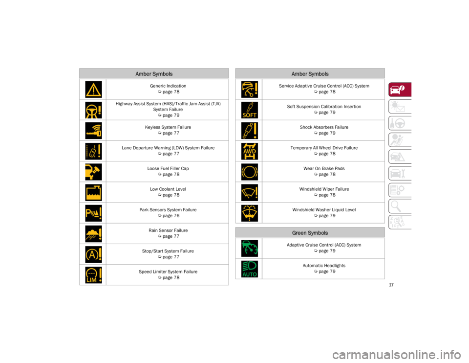
Generic Indication
Ú
page 78
Highway Assist System (HAS)/Traffic Jam Assist (TJA) System Failure
Ú
page 79
Keyless System Failure
Ú
page 77
Lane Departure Warning (LDW) System Failure
Ú
page 77
Loose Fuel Filler Cap
Ú
page 78
Low Coolant Level
Ú
page 78
Park Sensors System Failure
Ú
page 76
Rain Sensor Failure
Ú
page 77
Stop/Start System Failure
Ú
page 77
Speed Limiter System Failure
Ú
page 78
Amber Symbols
Service Adaptive Cruise Control (ACC) System
Ú
page 78
Soft Suspension Calibration Insertion
Ú
page 79
Shock Absorbers Failure
Ú
page 79
Temporary All Wheel Drive Failure
Ú
page 78
Wear On Brake Pads
Ú
page 78
Windshield Wiper Failure
Ú
page 78
Windshield Washer Liquid Level
Ú
page 79
Green Symbols
Adaptive Cruise Control (ACC) System
Ú
page 79
Automatic Headlights
Ú
page 79
Amber Symbols
23_GA_OM_EN_USC_t.book Page 17
Page 25 of 248
23
REMOTE START —
IF EQUIPPED
This system uses the key fob to start the
engine conveniently from outside the
vehicle while still maintaining security.
NOTE:
Obstructions between the vehicle and key fob
may reduce this range
Ú
page 239.
HOW TO USE REMOTE START
Push the Remote Start button on the key fob
twice within five seconds. The vehicle doors will
lock, the turn signals will flash twice, and the horn
will chirp twice. Pushing the Remote Start button
a third time shuts the engine off.
NOTE:
With Remote Start, the engine will only run for
15 minutes.
Remote Start can only be used twice.
If an engine fault is present or fuel level is low,
the vehicle will start and then shut down in 10
seconds.
The park lamps will turn on and remain on
during Remote Start mode.
For security, power window operation is
disabled when the vehicle is in the Remote
Start mode.
The ignition must be placed in the ACC position
before the Remote Start sequence can be
repeated for a third cycle.
All of the following conditions must be met before
the engine will remote start:
Gear selector in PARK
Doors closed
Hood closed
Trunk closed
Hazard switch off
Brake switch inactive (brake pedal not
pressed)
Battery at an acceptable charge level
Panic button not pushed
System not disabled from previous Remote
Start event
Vehicle Security system indicator flashing
Ignition in OFF position
Fuel level meets minimum requirement
Vehicle Security system is not signaling an
intrusion
Malfunction Indicator Light (MIL) is not
illuminated
TO EXIT REMOTE START MODE
To drive the vehicle after starting the Remote
Start system, either push and release the unlock
button on the key fob to unlock the doors, or
unlock the vehicle using Passive Entry via the
door handles, and disarm the Vehicle Security
system (if equipped). Then, prior to the end of the
15 minute cycle, push and release the START/
STOP ignition button while pressing the brake
pedal.
The Remote Start system will turn the engine off
with another push and release of the Remote
Start button on the key fob, or if the engine is
allowed to run for the entire 15 minute cycle.
REMOTE START COMFORT SYSTEMS —
I
F EQUIPPED
When Remote Start is activated, the heated
steering wheel and front heated seat features will
automatically activate when ambient
temperature is less than 39°F (4°C). These
features will stay on through the duration of
Remote Start.
NOTE:
This feature can be activated through the radio
system. Refer to the Information and Entertain -
ment System Owner’s Manual Supplement for
further information.
WARNING!
Do not start or run an engine in a closed
garage or confined area. Exhaust gas
contains Carbon Monoxide (CO) which is
odorless and colorless. Carbon Monoxide is
poisonous and can cause serious injury or
death when inhaled.
Keep key fobs away from children. Operation
of the Remote Start system, windows, door
locks or other controls could cause serious
injury or death.
23_GA_OM_EN_USC_t.book Page 23
Page 27 of 248
25
(Continued)
VOLUMETRIC/ANTI-LIFT PROTECTION —
I
F EQUIPPED
To ensure the correct operation of the
Volumetric/Anti-Lift Protection system,
completely close the side windows.
To disable the function, push the Volumetric/
Anti-Lift Protection button before activating the
alarm.
When the function is disabled, the light on the
Volumetric/Anti-Lift Protection button flashes for
several seconds.
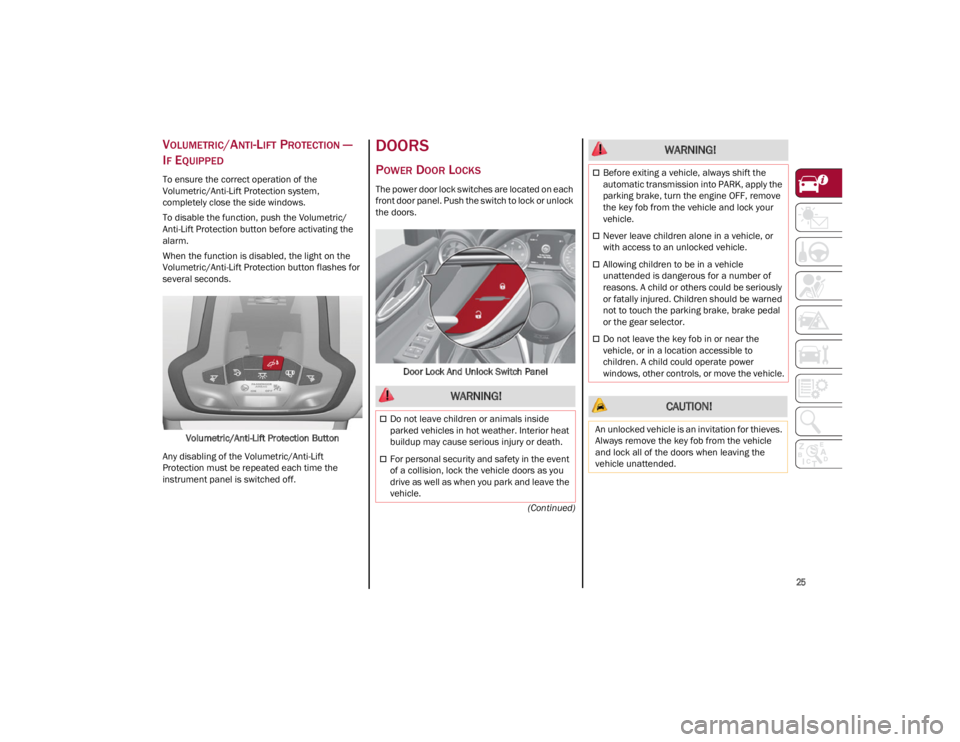
Volumetric/Anti-Lift Protection Button
Any disabling of the Volumetric/Anti-Lift
Protection must be repeated each time the
instrument panel is switched off.
DOORS
POWER DOOR LOCKS
The power door lock switches are located on each
front door panel. Push the switch to lock or unlock
the doors.
Door Lock And Unlock Switch Panel
WARNING!
Do not leave children or animals inside
parked vehicles in hot weather. Interior heat
buildup may cause serious injury or death.
For personal security and safety in the event
of a collision, lock the vehicle doors as you
drive as well as when you park and leave the
vehicle.
Before exiting a vehicle, always shift the
automatic transmission into PARK, apply the
parking brake, turn the engine OFF, remove
the key fob from the vehicle and lock your
vehicle.
Never leave children alone in a vehicle, or
with access to an unlocked vehicle.
Allowing children to be in a vehicle
unattended is dangerous for a number of
reasons. A child or others could be seriously
or fatally injured. Children should be warned
not to touch the parking brake, brake pedal
or the gear selector.
Do not leave the key fob in or near the
vehicle, or in a location accessible to
children. A child could operate power
windows, other controls, or move the vehicle.
CAUTION!
An unlocked vehicle is an invitation for thieves.
Always remove the key fob from the vehicle
and lock all of the doors when leaving the
vehicle unattended.
WARNING!
23_GA_OM_EN_USC_t.book Page 25
Page 62 of 248
GETTING TO KNOW YOUR VEHICLE
60
Proceed as follows:
1. With the ignition in the ON/RUN position, make sure the sunroof glass is fully closed
(sunshade open).
2. Open the driver’s side door, and place the ignition in the OFF position.
3. Within five seconds, place the ignition in the ACC or ON/RUN position.
4. Within 10 seconds, push and hold the sunroof close switch (forward). After 8 - 10
seconds of holding the switch, the re-initial -
ization process will begin. Continue to hold
the switch while the sunroof motor cycles,
and the sunshade will fully close.
5. Once the sunroof glass and the power sunshade have stopped motion, release the
sunroof close switch, then push and hold it
again within five seconds. Continue to hold
the switch while the sunshade fully opens,
the sunroof glass fully opens, followed by the
glass fully closing then the sunshade fully
closing.
6. Release the switch once the operations stop. Re-initialization of the sunroof motor is now
complete.
NOTE:
If the switch is released prior to full completion of
the operations described, the entire re-initializa -
tion procedure must be repeated from step 1.
7. Confirm express operations for the sunroof glass and sunshade are functional for
opening and closing operations.
SUNROOF MAINTENANCE
Use only a non-abrasive cleaner and a soft cloth
to clean the glass panel. Periodically check for
and clear out any debris that may have collected
in the tracks.
HOOD
OPENING THE HOOD
To open the hood, two latches must be released.
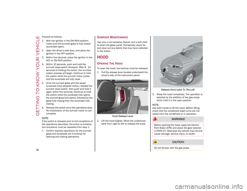
1. Pull the release lever located underneath the driver’s side of the instrument panel.
Hood Release Lever
2. Lift the hood slightly. Move the underhood latch from right to left to release the hood. Release Hood Latch To The Left
3. Raise the hood completely. The operation is assisted by the addition of two gas props
which hold it in the open position.
NOTE:
Use both hands to lift the hood. Before lifting,
check that the windshield wiper arms are not
raised from the windshield or in operation.
WARNING!
Before opening the hood, apply the Electric
Park Brake (EPB) and place the gear selector
in PARK (P). Otherwise the vehicle may roll and
cause damage, serious injury, or death.
CAUTION!
Do not tamper with the gas props.
23_GA_OM_EN_USC_t.book Page 60
Page 70 of 248
GETTING TO KNOW YOUR INSTRUMENT PANEL
68
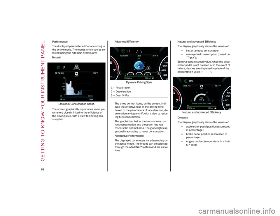
Performance
The displayed parameters differ according to
the active mode. The modes which can be se-
lected using the Alfa DNA system are:
Natural
Efficiency Consumption Graph
The screen graphically reproduces some pa -
rameters closely linked to the efficiency of
the driving style, with a view to limiting con -
sumption. Advanced Efficiency
Dynamic Driving Style
The three central icons, on the screen, indi -
cate the effectiveness of the driving style
linked to the parameters of: acceleration, de -
celeration and gear shift with a view to reduc -
ing fuel consumption.
The graphic bar below the icons shows cur -
rent consumption and the green line rep -
resents the optimal area. The globe lights up
gradually according to lower consumption.
Alternative Performance
The displayed parameters vary depending on
the active mode. The modes can be selected
through the Alfa DNA™ system and are as fol -
lows: Natural and Advanced Efficiency
The display graphically shows the values of:
○ instantaneous consumption
○ average fuel consumption (based on “Trip A”);
Below a certain speed value, when the accel -
erator pedal is not pressed or in the event of
failure, dashes are displayed in place of the
consumption value ("– –. –").
Natural and Advanced Efficiency
Dynamic
The display graphically shows the values of: ○ accelerator pedal position (expressed in percentage);
○ brake pedal position (expressed in percentage);
○ engine coolant temperature (H = hot/ C = cold).
1 — Acceleration
2 — Deceleration
3 — Gear Shifts
23_GA_OM_EN_USC_t.book Page 68
Page 73 of 248
71
RED WARNING LIGHTS
Air Bag Warning Light
This warning light will illuminate to
indicate a fault with the air bag, and will
turn on for four to eight seconds as a
bulb check when the ignition is placed in
the ON/RUN or ACC/ON/RUN position. This light
will illuminate with a single chime when a fault
with the air bag has been detected, it will stay on
until the fault is cleared. If the light is either not on
during startup, stays on, or turns on while driving,
have the system inspected at an authorized
dealer as soon as possible.
Brake Warning Light
This warning light monitors various
brake functions, including brake fluid
level and parking brake application. If
the brake light turns on it may indicate
that the parking brake is applied, that the brake
fluid level is low, or that there is a problem with
the Anti-Lock Brake System reservoir.
If the light remains on when the parking brake
has been disengaged, and the fluid level is at the
full mark on the master cylinder reservoir, it
indicates a possible brake hydraulic system
malfunction or that a problem with the Brake
Booster has been detected by the Anti-Lock
Brake System (ABS) / Electronic Stability Control
(ESC) system. In this case, the light will remain on
until the condition has been corrected. If the
problem is related to the brake booster, the ABS
pump will run when applying the brake, and a
brake pedal pulsation may be felt during each
stop. The dual brake system provides a reserve braking
capacity in the event of a failure to a portion of the
hydraulic system. A leak in either half of the dual
brake system is indicated by the Brake Warning
Light, which will turn on when the brake fluid level
in the master cylinder has dropped below a
specified level.
The light will remain on until the cause is
corrected.
NOTE:
The light may flash momentarily during sharp
cornering maneuvers, which change fluid level
conditions. The vehicle should have service
performed, and the brake fluid level checked.
If brake failure is indicated, immediate repair is
necessary.
Vehicles equipped with the Anti-Lock Brake
System (ABS) are also equipped with Electronic
Brake Force Distribution (EBD). In the event of an
EBD failure, the Brake Warning Light will turn on
along with the ABS Light. Immediate repair to the
ABS system is required.
Operation of the Brake Warning Light can be
checked by turning the ignition switch from the
OFF position to the ON/RUN position. The light
should illuminate for approximately two seconds.
The light should then turn off unless the parking
brake is applied or a brake fault is detected. If the
light does not illuminate, have the light inspected
by an authorized dealer.
The light also will turn on when the parking brake
is applied with the ignition switch in the ON/RUN
position.
NOTE:
This light shows only that the parking brake is
applied. It does not show the degree of brake
application.
Seat Belt Reminder Warning Light
When the ignition is first placed in the
ON/RUN position, if the driver’s seat
belt is unbuckled, a chime will sound
and the light will turn on. When driving,
if the driver or front passenger seat belt remains
unbuckled, the Seat Belt Reminder Light will flash
or remain on continuously and a chime will sound
Ú
page 144.
WARNING!
If the warning light does not turn on when the
ignition is placed in the ON/RUN position or if
it stays on when driving (together with the
message on the display), there might be a
malfunction in the restraint systems; This
could mean the air bags or pretensioners
may not deploy in the event of an accident or,
they could deploy erroneously. This could
result in serious injuries or death. Have the
vehicle checked by qualified technician
immediately.
Driving a vehicle with a red brake warning
light on is dangerous. Part of the brake
system may have failed. It will take longer to
stop the vehicle in such circumstances. This
could result in a collision and serious injuries
or death. Have the vehicle checked by a
qualified technician immediately.
23_GA_OM_EN_USC_t.book Page 71