bulb ALFA ROMEO GIULIA 2023 Owners Manual
[x] Cancel search | Manufacturer: ALFA ROMEO, Model Year: 2023, Model line: GIULIA, Model: ALFA ROMEO GIULIA 2023Pages: 248, PDF Size: 9.62 MB
Page 14 of 248
12
ENGINE COMPARTMENT....................... 187
Checking Levels — 2.0L Engine .......... 187
Checking Levels — 2.9L Engine .........188
Engine Oil ............................................. 188
Engine Coolant ..................................... 189
Washer Fluid For Windshield/
Headlights ............................................ 189 Brake Fluid ...........................................190
Automatic Transmission Activation
System Oil ............................................ 190 Useful Advice For Extending The Life
Of Your Battery ..................................... 190 Battery ..................................................190
Pressure Washing ................................ 191
BATTERY RECHARGING......................... 191
Important Notes ...................................191
VEHICLE MAINTENANCE ....................... 192
Engine Oil ............................................. 192
Engine Oil Filter ....................................192
Engine Air Cleaner ............................... 192
Air Conditioning System
Maintenance ........................................192 Lubricating Moving Parts Of The
Bodywork ..............................................193 Windshield Wiper .................................193
Exhaust System ...................................194
Engine Cooling System ........................ 195
Braking System ....................................196
Automatic Transmission ......................196
Replacing The Battery ......................... 196
Fuses ................................................... 197
Bulb Replacement ............................... 202
TIRES ..................................................... 206
Tire Safety Information ....................... 206
Tires — General Information .............. 212
Spare Tires — If Equipped .................. 216
Wheel And Wheel Trim Care ............... 217
Tire Types ............................................. 217
Snow Traction Devices ........................ 218
Tire Rotation Recommendations........ 219
DEPARTMENT OF TRANSPORTATION
UNIFORM TIRE QUALITY GRADES ........ 219
Treadwear ............................................ 219
Traction Grades ................................... 220
Temperature Grades ........................... 220
STORING THE VEHICLE ......................... 220
BODYWORK ............................................ 221
Protection Against Atmospheric
Agents .................................................. 221 Corrosion Warranty.............................. 221
Preserving The Bodywork.................... 221
INTERIORS.............................................. 222
Seats And Fabric Parts........................ 222
Leather Seats ...................................... 222
Plastic And Coated Parts .................... 223
Alcantara Parts — If Equipped ............ 223
Genuine Leather Surfaces —
If Equipped ........................................... 223 Carbon Fiber Parts .............................. 223
TECHNICAL SPECIFICATIONS
VEHICLE IDENTIFICATION NUMBER
(VIN) ....................................................... 224
Vehicle Identification Number (VIN)
Plate ..................................................... 224
ENGINE .................................................. 224
POWER SUPPLY ..................................... 225 TRANSMISSION ..................................... 225BRAKES.................................................. 226
SUSPENSION ......................................... 226
STEERING SYSTEM ............................... 226DIMENSIONS — 2.0L ENGINE ............... 227
DIMENSIONS — 2.9L Engine ................ 228
WEIGHTS — 2.0L ENGINE ..................... 229
WEIGHTS — 2.9L ENGINE ..................... 229
FUEL REQUIREMENTS .......................... 230
Reformulated Gasoline....................... 230
Gasoline/Oxygenate Blends ............... 230
CNG And LP Fuel System
Modifications ....................................... 230 Methylcyclopentadienyl Manganese
Tricarbonyl (MMT) In Gasoline ........... 230 Materials Added To Fuel ..................... 230
Fuel System Cautions ......................... 231
FLUID CAPACITIES ................................. 231
2.0L Engine ......................................... 231
2.9L V6 Engine .................................... 232
ENGINE FLUIDS AND LUBRICANTS ...... 233
CHASSIS FLUIDS AND LUBRICANTS..... 234 PERFORMANCE — 2.0L ENGINE........... 235PERFORMANCE — 2.9L ENGINE........... 235
23_GA_OM_EN_USC_t.book Page 12
Page 23 of 248
21
Proceed in reverse order to reassemble the key
fob.
Programming And Requesting Additional
Key Fobs
Programming the key fob may be performed by an
authorized dealer.
NOTE:
Once a key fob is programmed to a vehicle, it
cannot be repurposed and reprogrammed to
another vehicle.
Only key fobs that are programmed to the
vehicle electronics can be used to start and
operate the vehicle.Duplication of key fobs may be performed at an
authorized dealer. This procedure consists of
programming a blank key fob to the vehicle
electronics. A blank key fob is one that has never
been programmed.
NOTE:
When having the Engine Immobilizer system
serviced, bring all vehicle keys with you to an
authorized dealer.
Keys must be ordered to the correct key cut to
match the vehicle locks.
For Quadrifoglio models, if you need a
replacement key fob, contact an authorized
dealer.
ENGINE IMMOBILIZER
SYSTEM
The Engine Immobilizer system prevents
unauthorized vehicle operation by disabling the
engine. The system does not need to be armed or
activated. Operation is automatic, regardless of
whether the vehicle is locked or unlocked.
The system uses a key fob, keyless push button
ignition and a Radio Frequency (RF) receiver to
prevent unauthorized vehicle operation.
Therefore, only key fobs that are programmed to the vehicle can be used to start and operate the
vehicle. The system will shut the engine off in two
seconds if an invalid key fob is used to start the
engine.
After placing the ignition switch in the ON/RUN
position, the Vehicle Security Light will turn on for
three seconds for a bulb check. If the light
remains on after the bulb check, it indicates that
there is a problem with the electronics. In
addition, if the light begins to flash after the bulb
check, it indicates that someone used an invalid
key fob to start the engine. Either of these
conditions will result in the engine being shut off
after two seconds.
If the Vehicle Security Light turns on during
normal vehicle operation (vehicle running for
longer than 10 seconds), it indicates that there is
a fault in the electronics. Should this occur, have
the vehicle serviced as soon as possible by an
authorized dealer.
All of the key fobs provided with your new vehicle
have been programmed to the vehicle
electronics.
NOTE:
A key fob that has not been programmed is also
considered an invalid key
Ú
page 239.
WARNING!
The integrated key fob contains a coin cell
battery. Do not ingest the battery; there is a
chemical burn hazard. If the coin cell battery
is swallowed, it can cause severe internal
burns in just two hours and can lead to
death.
If you think a battery may have been
swallowed or placed inside any part of the
body, seek immediate medical attention.
Keep new and used batteries away from
children. If the battery compartment does
not close securely, stop using the product
and keep it away from children.
CAUTION!
The battery replacement operation must be done
with care, in order not to damage the key fob.
WARNING!
Always remove the key fobs from the vehicle
and lock all doors when leaving the vehicle
unattended.
Always remember to place the ignition in the
OFF position.
CAUTION!
The Engine Immobilizer system is not
compatible with some aftermarket Remote
Start systems. Use of these systems may
result in vehicle starting problems and loss of
security protection.
23_GA_OM_EN_USC_t.book Page 21
Page 73 of 248
71
RED WARNING LIGHTS
Air Bag Warning Light
This warning light will illuminate to
indicate a fault with the air bag, and will
turn on for four to eight seconds as a
bulb check when the ignition is placed in
the ON/RUN or ACC/ON/RUN position. This light
will illuminate with a single chime when a fault
with the air bag has been detected, it will stay on
until the fault is cleared. If the light is either not on
during startup, stays on, or turns on while driving,
have the system inspected at an authorized
dealer as soon as possible.
Brake Warning Light
This warning light monitors various
brake functions, including brake fluid
level and parking brake application. If
the brake light turns on it may indicate
that the parking brake is applied, that the brake
fluid level is low, or that there is a problem with
the Anti-Lock Brake System reservoir.
If the light remains on when the parking brake
has been disengaged, and the fluid level is at the
full mark on the master cylinder reservoir, it
indicates a possible brake hydraulic system
malfunction or that a problem with the Brake
Booster has been detected by the Anti-Lock
Brake System (ABS) / Electronic Stability Control
(ESC) system. In this case, the light will remain on
until the condition has been corrected. If the
problem is related to the brake booster, the ABS
pump will run when applying the brake, and a
brake pedal pulsation may be felt during each
stop. The dual brake system provides a reserve braking
capacity in the event of a failure to a portion of the
hydraulic system. A leak in either half of the dual
brake system is indicated by the Brake Warning
Light, which will turn on when the brake fluid level
in the master cylinder has dropped below a
specified level.
The light will remain on until the cause is
corrected.
NOTE:
The light may flash momentarily during sharp
cornering maneuvers, which change fluid level
conditions. The vehicle should have service
performed, and the brake fluid level checked.
If brake failure is indicated, immediate repair is
necessary.
Vehicles equipped with the Anti-Lock Brake
System (ABS) are also equipped with Electronic
Brake Force Distribution (EBD). In the event of an
EBD failure, the Brake Warning Light will turn on
along with the ABS Light. Immediate repair to the
ABS system is required.
Operation of the Brake Warning Light can be
checked by turning the ignition switch from the
OFF position to the ON/RUN position. The light
should illuminate for approximately two seconds.
The light should then turn off unless the parking
brake is applied or a brake fault is detected. If the
light does not illuminate, have the light inspected
by an authorized dealer.
The light also will turn on when the parking brake
is applied with the ignition switch in the ON/RUN
position.
NOTE:
This light shows only that the parking brake is
applied. It does not show the degree of brake
application.
Seat Belt Reminder Warning Light
When the ignition is first placed in the
ON/RUN position, if the driver’s seat
belt is unbuckled, a chime will sound
and the light will turn on. When driving,
if the driver or front passenger seat belt remains
unbuckled, the Seat Belt Reminder Light will flash
or remain on continuously and a chime will sound
Ú
page 144.
WARNING!
If the warning light does not turn on when the
ignition is placed in the ON/RUN position or if
it stays on when driving (together with the
message on the display), there might be a
malfunction in the restraint systems; This
could mean the air bags or pretensioners
may not deploy in the event of an accident or,
they could deploy erroneously. This could
result in serious injuries or death. Have the
vehicle checked by qualified technician
immediately.
Driving a vehicle with a red brake warning
light on is dangerous. Part of the brake
system may have failed. It will take longer to
stop the vehicle in such circumstances. This
could result in a collision and serious injuries
or death. Have the vehicle checked by a
qualified technician immediately.
23_GA_OM_EN_USC_t.book Page 71
Page 79 of 248
77
Forward Collision Warning (FCW) System
Failure — If Equipped
The telltale will illuminate in the case of
failure of the Forward Collision Warning
system.
Contact an authorized dealer as soon as possible.
Stop/Start System Failure
This telltale will illuminate to report a
Stop/Start system failure.
Contact an authorized dealer as soon as possible
to have the failure eliminated.
Rain Sensor Failure
The telltale will illuminate in the case of
failure of the automatic windshield
wiper.
Contact an authorized dealer as soon as possible.
Dusk Sensor Failure
The telltale will illuminate in the case of
failure of the automatic low beam
alignment.
Contact an authorized dealer as soon as possible.
Blind Spot Monitoring System Failure —
If Equipped
The telltale will illuminate in the event of
a Blind Spot Monitoring system failure.
Contact an authorized dealer as soon as possible.
Fuel Level Sensor Failure
The telltale will illuminate in the event of
fuel level sensor failure.
Contact an authorized dealer as soon as possible.
Exterior Lights Failure
The telltale will illuminate to indicate a
failure on the following lights: daytime
running lights (DRLs) / parking lights /
trailer turn signal indicators (if present) /
trailer lights (if present) / side lights / turn signal
indicators / rear fog light / reversing light / brake
lights / license plate lights.
The failure may be caused by a blown bulb, a
blown protection fuse, or an interruption of the
electrical connection.
Replace the bulb or the relevant fuse. Contact an
authorized dealer.
Keyless System Failure
The telltale will illuminate in the event of
keyless system failure.
Contact an authorized dealer as soon as possible.
Fuel Cut-Off System Failure
The telltale will illuminate in the event of
fuel cut-off system failure.
Contact an authorized dealer as soon as possible.
Lane Departure Warning (LDW) System
Failure — If Equipped
The telltale will illuminate in the event of
a fault in the Lane Departure Warning
system.
Contact an authorized dealer as soon as possible.
Automatic High Beam Headlights
Failure — If Equipped
The telltale will illuminate to report a
failure of the automatic high beam
headlights.
Contact an authorized dealer as soon as possible
to have the failure eliminated.
Automatic Transmission Fluid
Overheating
The telltale will illuminate in the case of
transmission overheating, after a partic -
ularly demanding use. In this case an
engine performance limitation is carried
out.
Wait for the telltale to turn off with the engine off
or idling.
Audio System Failure
The telltale will illuminate to report a
failure of the audio system.
Contact an authorized dealer as soon as possible
to have the failure eliminated.
23_GA_OM_EN_USC_t.book Page 77
Page 82 of 248
GETTING TO KNOW YOUR INSTRUMENT PANEL
80
ONBOARD DIAGNOSTIC SYSTEM (OBD II)
C
YBERSECURITY
Your vehicle is required to have OBD II and a
connection port to allow access to information
related to the performance of your emissions
controls. Authorized service technicians may
need to access this information to assist with the
diagnosis and service of your vehicle and
emissions system.
EMISSIONS INSPECTION
AND MAINTENANCE
PROGRAMS
In some localities, it may be a legal requirement
to pass an inspection of your vehicle's emissions
control system. Failure to pass could prevent
vehicle registration.
For states that require an Inspection
and Maintenance (I/M), this check
verifies the Malfunction Indicator Light
(MIL) is functioning and is not on when
the engine is running, and that the OBD II system
is ready for testing.
Normally, the OBD II system will be ready. The
OBD II system may not be ready if your vehicle
was recently serviced, recently had a depleted
battery or a battery replacement. If the OBD II
system should be determined not ready for the
I/M test, your vehicle may fail the test.
Your vehicle has a simple ignition actuated test,
which you can use prior to going to the test
station. To check if your vehicle's OBD II system is
ready, you must do the following:
1. Cycle the ignition switch to the ON position, but do not crank or start the engine.
NOTE:
If you crank or start the engine, you will have to
start this test over. 2. As soon as you cycle the ignition switch to the
ON position, you will see the Malfunction Indi -
cator Light (MIL) symbol come on as part of a
normal bulb check.
3. Approximately 15 seconds later, one of two things will happen:
• The MIL will flash for about 10 seconds
and then return to being fully illuminateduntil you turn OFF the ignition or start the engine. This means that your vehicle'sOBD II system is not ready and you should
not proceed to the I/M station.
• The MIL will not flash at all and will remain
fully illuminated until you place the ignition
in t
he off position or start the engine. This
means that your vehicle's OBD II system is ready and you can proceed to the I/M
station.
If your OBD II system is not ready, you should see
an authorized dealer or repair facility. If your
vehicle was recently serviced or had a battery
failure or replacement, you may need to do
nothing more than drive your vehicle as you
normally would in order for your OBD II system to
update. A recheck with the above test routine
may then indicate that the system is now ready.
Regardless of whether your vehicle's OBD II
system is ready or not, if the MIL is illuminated
during normal vehicle operation you should have
your vehicle serviced before going to the I/M
station. The I/M station can fail your vehicle
because the MIL is on with the engine running.
WARNING!
ONLY an authorized service technician
should connect equipment to the OBD II
connection port in order to read the VIN,
diagnose, or service your vehicle.
If unauthorized equipment is connected to
the OBD II connection port, such as a
driver-behavior tracking device, it may:
• Be possible that vehicle systems,
including safety related systems, couldbe impaired or a loss of vehicle controlcould occur that may result in an acci-dent involving serious injury or death.
• Access, or allow others to access, infor-
mation stored in your vehicle systems,including personal information.
23_GA_OM_EN_USC_t.book Page 80
Page 152 of 248
SAFETY
150
Air Bag System Components
Occupant Restraint Controller (ORC)
Air Bag Warning Light
Steering Wheel and Column
Instrument Panel
Knee Impact Bolsters
Driver and Front Passenger Air Bags
Seat Belt Buckle Switch
Supplemental Side Air Bags
Supplemental Knee Air Bags
Front and Side Impact Sensors
Seat Belt Pretensioners
Seat Track Position Sensors
Air Bag Warning Light
The Occupant Restraint Controller
(ORC) monitors the readiness of the
electronic parts of the air bag system
whenever the ignition switch is in the
START or ON/RUN position. If the ignition switch
is in the OFF position or in the ACC position, the
air bag system is not on and the air bags will not
inflate.
The ORC contains a backup power supply system
that may deploy the air bag system even if the
battery loses power or it becomes disconnected
prior to deployment.
The ORC turns on the Air Bag Warning Light in the
instrument panel for approximately four to eight
seconds for a self-check when the ignition switch
is first in the ON/RUN position. After the
self-check, the Air Bag Warning Light will turn off.
If the ORC detects a malfunction in any part of the
system, it turns on the Air Bag Warning Light, either momentarily or continuously. A single
chime will sound to alert you if the light comes on
again after initial startup.
The ORC also includes diagnostics that will
illuminate the instrument panel Air Bag Warning
Light if a malfunction is detected that could affect
the air bag system. The diagnostics also record
the nature of the malfunction. While the air bag
system is designed to be maintenance free, if any
of the following occurs, have an authorized dealer
service the air bag system immediately.
The Air Bag Warning Light does not come on
during the four to eight seconds when the
ignition switch is first in the ON/RUN position.
The Air Bag Warning Light remains on after the
four to eight-second interval.
The Air Bag Warning Light comes on intermit
-
tently or remains on while driving.
NOTE:
If the speedometer, tachometer, or any engine
related gauges are not working, the Occupant
Restraint Controller (ORC) may also be disabled.
In this condition the air bags may not be ready to
inflate for your protection. Have an authorized
dealer service the air bag system immediately.
Redundant Air Bag Warning Light
If a fault with the Air Bag Warning Light
is detected, which could affect the
Supplemental Restraint System (SRS),
the Redundant Air Bag Warning Light
will illuminate on the instrument panel. The
Redundant Air Bag Warning Light will stay on until
the fault is cleared. In addition, a single chime will
sound to alert you that the Redundant Air Bag
Warning Light has come on and a fault has been
detected. If the Redundant Air Bag Warning Light
comes on intermittently or remains on while
driving have an authorized dealer service the
vehicle immediately.
For additional information regarding the
Redundant Air Bag Warning Light, see
Ú
page 70.
Front Air Bags
This vehicle has front air bags and lap/shoulder
belts for both the driver and front passenger. The
front air bags are a supplement to the seat belt
restraint systems. The driver front air bag is
mounted in the center of the steering wheel. The
passenger front air bag is mounted in the
instrument panel, above the glove compartment.
The words “SRS AIRBAG” or “AIRBAG” are
embossed on the air bag covers.
WARNING!
Ignoring the Air Bag Warning Light in your
instrument panel could mean you won’t have
the air bag system to protect you in a collision.
If the light does not come on as a bulb check
when the ignition is first turned on, stays on
after you start the vehicle, or if it comes on as
you drive, have an authorized dealer service
the air bag system immediately.
23_GA_OM_EN_USC_t.book Page 150
Page 169 of 248
167
(Continued)
(Continued)
SAFETY CHECKS YOU SHOULD MAKE
I
NSIDE THE VEHICLE
Seat Belts
Inspect the seat belt system periodically,
checking for cuts, frays, and loose parts.
Damaged parts must be replaced immediately.
Do not disassemble or modify the system.
If your vehicle is involved in a collision, or if you
have questions regarding the seat belt or
retractor conditions, take your vehicle to an
authorized FCA dealer or authorized FCA Certified
Collision Care Program facility for inspection.
Air Bag Warning Light
The Air Bag Warning Light will turn on for
four to eight seconds as a bulb check
when the ignition switch is first turned to
ON/RUN. If the light is either not on
during starting, stays on, or turns on while driving,
have the system inspected at an authorized
dealer as soon as possible. After the bulb check,
this light will illuminate with a single chime when
a fault with the Air Bag System has been
detected. It will stay on until the fault is removed.
If the light comes on intermittently or remains on
while driving, have an authorized dealer service
the vehicle immediately
Ú
page 144.
Defroster
Check operation by selecting the defrost mode
and place the blower control on high speed. You
should be able to feel the air directed against the
windshield. See an authorized dealer for service if
your defroster is inoperable.
Floor Mat Safety Information
Always use floor mats designed to fit your vehicle.
Only use a floor mat that does not interfere with
the operation of the accelerator, brake or clutch
pedals. Only use a floor mat that is securely
attached using the floor mat fasteners so it
cannot slip out of position and interfere with the
accelerator, brake or clutch pedals or impair safe
operation of your vehicle in other ways.
WARNING!
An improperly attached, damaged, folded, or
stacked floor mat, or damaged floor mat
fasteners may cause your floor mat to
interfere with the accelerator, brake, or clutch
pedals and cause a loss of vehicle control. To
prevent SERIOUS INJURY or DEATH:
ALWAYS securely attach your floor
mat using the floor mat fasteners. DO
NOT install your floor mat upside down
or turn your floor mat over. Lightly pull
to confirm mat is secured using the floor mat
fasteners on a regular basis.
ALWAYS REMOVE THE EXISTING
FLOOR MAT FROM THE VEHICLE
before installing any other floor mat.
NEVER install or stack an additional
floor mat on top of an existing floor mat.
ONLY install floor mats designed to fit your
vehicle. NEVER install a floor mat that cannot
be properly attached and secured to your
vehicle. If a floor mat needs to be replaced,
only use a FCA approved floor mat for the
specific make, model, and year of your vehicle.
ONLY use the driver’s side floor mat on the
driver’s side floor area. To check for
interference, with the vehicle properly
parked with the engine off, fully press the
accelerator, the brake, and the clutch pedal
(if present) to check for interference. If your
floor mat interferes with the operation of any
pedal, or is not secure to the floor, remove
the floor mat from the vehicle and place the
floor mat in your trunk.
ONLY use the passenger’s side floor mat on
the passenger’s side floor area.
ALWAYS make sure objects cannot fall or
slide into the driver’s side floor area when
the vehicle is moving. Objects can become
trapped under accelerator, brake, or clutch
pedals and could cause a loss of vehicle
control.
NEVER place any objects under the floor mat
(e.g., towels, keys, etc.). These objects could
change the position of the floor mat and may
cause interference with the accelerator,
brake, or clutch pedals.
If the vehicle carpet has been removed and
re-installed, always properly attach carpet to
the floor and check the floor mat fasteners
are secure to the vehicle carpet. Fully press
each pedal to check for interference with the
accelerator, brake, or clutch pedals then
re-install the floor mats.
WARNING!
23_GA_OM_EN_USC_t.book Page 167
Page 171 of 248
169
Have a flat tire or a burnt-out bulb?
At times, a problem such as these may interfere
with your driving experience.
The section on emergencies can help you to deal
with critical situations independently.
HAZARD WARNING
FLASHERS
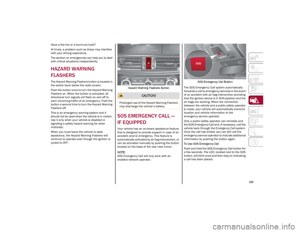
The Hazard Warning Flashers button is located in
the switch bank below the radio screen.
Push the button once to turn the Hazard Warning
Flashers on. When the button is activated, all
directional turn signals will flash on and off to
warn oncoming traffic of an emergency. Push the
button a second time to turn the Hazard Warning
Flashers off.
This is an emergency warning system and it
should not be used when the vehicle is in motion.
Use it only when your vehicle is disabled or
signaling a safety hazard warning for other
motorists.
When you must leave the vehicle to seek
assistance, the Hazard Warning Flashers will
continue to operate even though the ignition is
cycled to OFF.Hazard Warning Flashers Button
SOS EMERGENCY CALL —
IF EQUIPPED
Your vehicle has an on-board assistance feature
that is designed to provide support in case of an
accident and/or emergency. This feature is
automatically activated by air bag intervention, or
can be activated manually by pushing the button
located on the base of the rear view mirror.
NOTE:
SOS Emergency Call will only work with an
enabled network operator. SOS Emergency Call Button
The SOS Emergency Call system automatically
forwards a call to emergency services in the event
of an accident with air bag intervention providing
that the ignition device is in RUN position and the
air bags are working. When the connection
between the vehicle and a public safety operator
is made, your vehicle will automatically transmit
location and vehicle information to the
emergency service operator.
Only a public safety operator can remotely end
the SOS Emergency Call and, if necessary, call the
vehicle back through the Emergency Call system.
Once the call has ended, you can still call the
emergency service operator to indicate additional
information by pushing the button again.
To Use SOS Emergency Call
Push and hold the SOS Emergency Call button for
a few seconds. The LED, located next to the SOS
button, will blink once and then stay on indicating
a call has been placed.
CAUTION!
Prolonged use of the Hazard Warning Flashers
may discharge the vehicle’s battery.
23_GA_OM_EN_USC_t.book Page 169
Page 204 of 248
SERVICING AND MAINTENANCE
202
BULB REPLACEMENT
General Instructions
Before replacing a bulb, check the contacts for oxidation.
Replace blown bulbs with others of the same type and power.
After replacing a headlight bulb, always check its alignment.
When a light is not working, check that the corresponding fuse is intact before changing the bulb
Ú
page 197.
NOTE:
In some particular climate conditions, such as low temperature, humidity, or after washing the car, a thin condensation layer may form on the internal
surfaces of the front and rear headlights. This condensation will disappear after switching on the headlights.
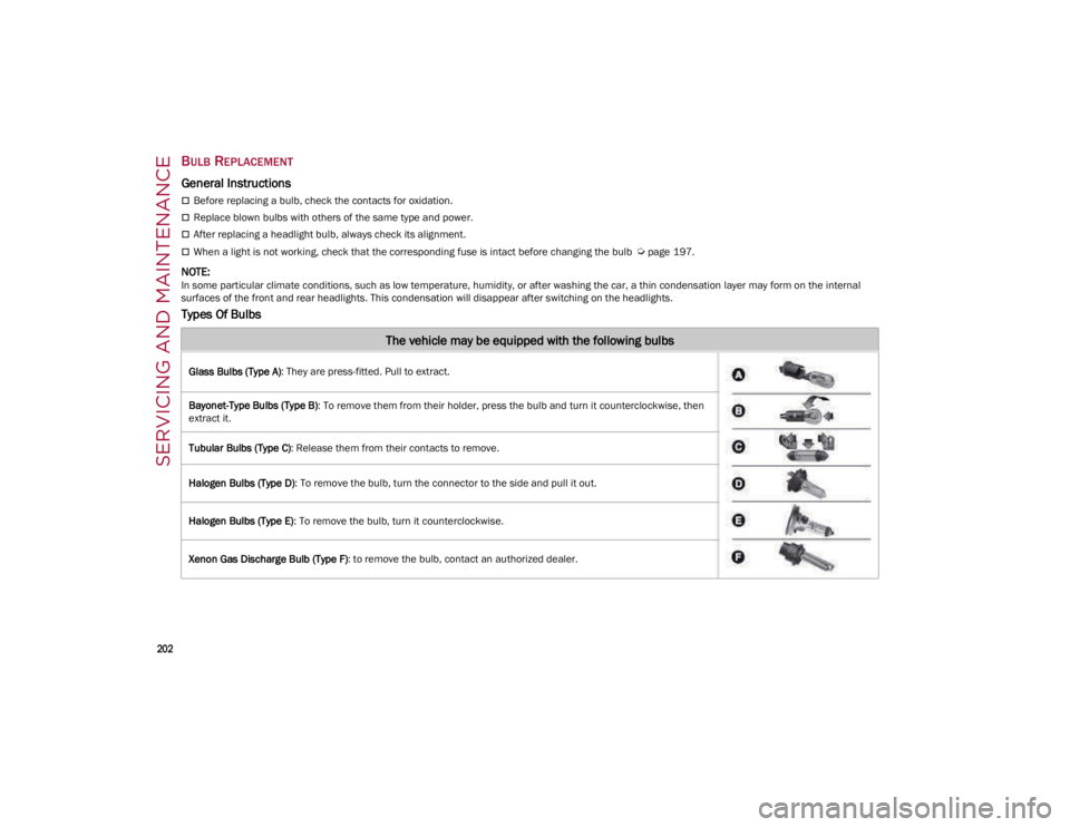
Types Of Bulbs
The vehicle may be equipped with the following bulbs
Glass Bulbs (Type A): They are press-fitted. Pull to extract.
Bayonet-Type Bulbs (Type B) : To remove them from their holder, press the bulb and turn it counterclockwise, then
extract it.
Tubular Bulbs (Type C) : Release them from their contacts to remove.
Halogen Bulbs (Type D) : To remove the bulb, turn the connector to the side and pull it out.
Halogen Bulbs (Type E) : To remove the bulb, turn it counterclockwise.
Xenon Gas Discharge Bulb (Type F) : to remove the bulb, contact an authorized dealer.
23_GA_OM_EN_USC_t.book Page 202
Page 205 of 248
203
Replacement Bulbs
Replacing Exterior Bulbs
NOTE:
Only replace the bulb when the engine is off. Also
ensure that the engine is cold, to prevent the risk
of burns.
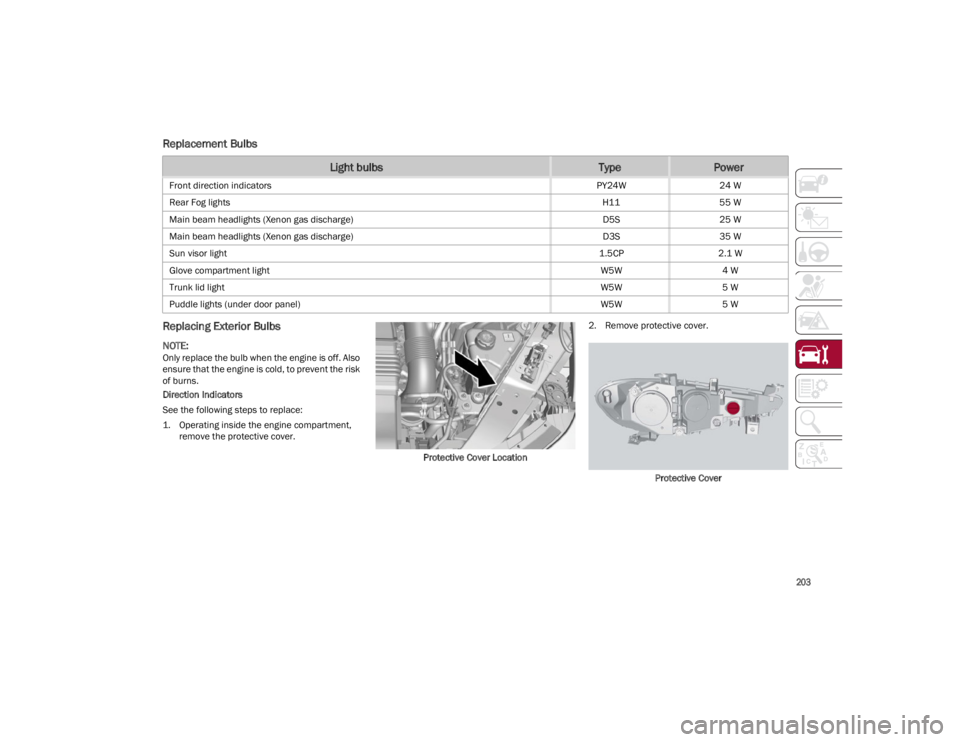
Direction Indicators
See the following steps to replace:
1. Operating inside the engine compartment,remove the protective cover.
Protective Cover Location2. Remove protective cover.
Protective Cover
Light bulbsTypePower
Front direction indicators PY24W24 W
Rear Fog lights H1155 W
Main beam headlights (Xenon gas discharge) D5S25 W
Main beam headlights (Xenon gas discharge) D3S35 W
Sun visor light 1.5CP2.1 W
Glove compartment light W5W4 W
Trunk lid light W5W5 W
Puddle lights (under door panel) W5W5 W
23_GA_OM_EN_USC_t.book Page 203