warning lights Alfa Romeo Giulia Quadrifoglio 2017 User Guide
[x] Cancel search | Manufacturer: ALFA ROMEO, Model Year: 2017, Model line: Giulia Quadrifoglio, Model: Alfa Romeo Giulia Quadrifoglio 2017Pages: 268, PDF Size: 110.98 MB
Page 70 of 268
The displayed parameters are related to
vehicle stability, the graphs illustrate the
trend of the longitudinal/lateral
accelerations (G-meter information),
considering gravity acceleration as a
reference unit.
Lateral acceleration peaks are also
indicated.
7.Vehicle Range
Indicates the miles left before the fuel
tankisempty.
Displays the position by indicating the
cardinal direction.
8. Failure Warning Lights
Area dedicated to displaying failures,
the following symbols could be
displayed on rotation:
Low criticality symbols (yellow
amber).
High criticality symbols (red). 9.
Odometer
Indicates the total miles travelled.
PARAMETERS SET BY USER
Multiple settings can be programmed
by the user using the Connect system.
This section describes only the basic
settings:
Units & Language
Time&Date
Cluster
To access the settings list in the
Connect system, proceed as follows:
1. Press the MENU button to access
the main menu
2. Select “Settings” from the main
menu using the Rotary Knob Units & Language
The following settings can be modified
under the “Units & Language” menu:
Measure Units: select US, metric, or
custom. The custom option allows for
individual selection of the unit measures
GUID-05036S0014NAAcceleration Stability Gauge
GUID-05036S0015EMConnect System
GUID-05036S0040EMMENU button
GUID-05036S0016EMUnits & Language Selectable Menu Options
68
GETTING TO KNOW YOUR INSTRUMENT PANEL
Page 72 of 268
WARNING LIGHTS
AND MESSAGES ON
THE INSTRUMENT
PANEL
The following pages consist of warning
lights and messages.
Note:
The warning light switches on
together with a dedicated message
and/or chime when applicable. These
indications are precautionary and as
such must not be considered as
exhaustive and/or alternative to the
information contained in the Owner’s
Manual, which you are advised to read
carefully in all cases. Always refer to
the information in this section in the
event of a failure indication.
The failure indicators appearing on
the display are divided into two
categories: very serious and less
serious faults. Serious faults are
indicated by a repeated and prolonged
warning "cycle.” Less serious faults are
indicated by a warning "cycle" with a
shorter duration. You can stop the
warning cycle in both cases by
pressing the button located on the
windshield wiper lever. The instrument
panel warning light will stay on until the
cause of the failure is eliminated.
70
GETTING TO KNOW YOUR INSTRUMENT PANEL
Page 73 of 268
Red Warning Lights
Warning LightWhat It Means What To Do
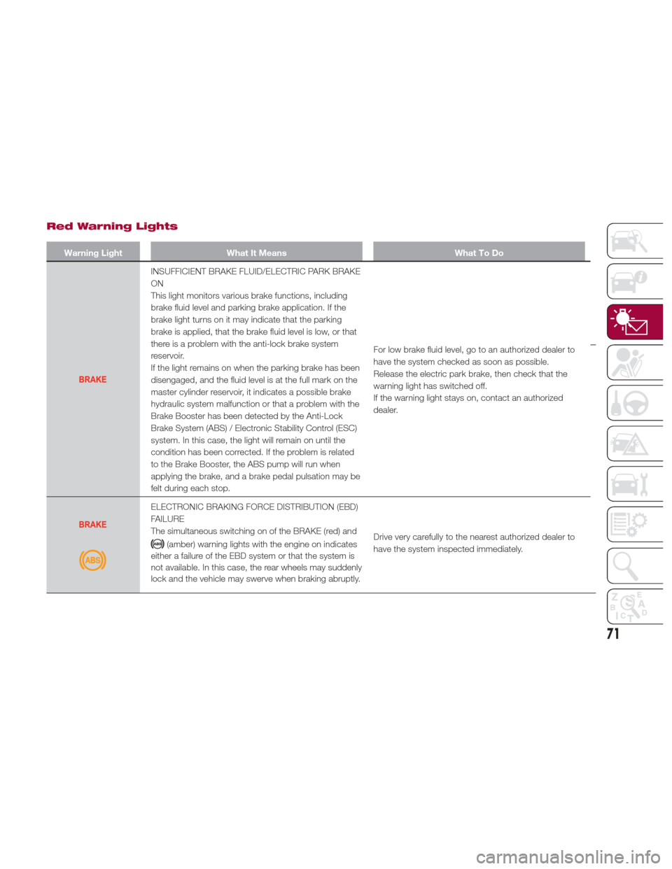
INSUFFICIENT BRAKE FLUID/ELECTRIC PARK BRAKE
ON
This light monitors various brake functions, including
brake fluid level and parking brake application. If the
brake light turns on it may indicate that the parking
brake is applied, that the brake fluid level is low, or that
there is a problem with the anti-lock brake system
reservoir.
If the light remains on when the parking brake has been
disengaged, and the fluid level is at the full mark on the
master cylinder reservoir, it indicates a possible brake
hydraulic system malfunction or that a problem with the
Brake Booster has been detected by the Anti-Lock
Brake System (ABS) / Electronic Stability Control (ESC)
system. In this case, the light will remain on until the
condition has been corrected. If the problem is related
to the Brake Booster, the ABS pump will run when
applying the brake, and a brake pedal pulsation may be
felt during each stop.For low brake fluid level, go to an authorized dealer to
have the system checked as soon as possible.
Release the electric park brake, then check that the
warning light has switched off.
If the warning light stays on, contact an authorized
dealer.
ELECTRONIC BRAKING FORCE DISTRIBUTION (EBD)
FAILURE
The simultaneous switching on of the BRAKE (red) and
(amber) warning lights with the engine on indicates
either a failure of the EBD system or that the system is
not available. In this case, the rear wheels may suddenly
lock and the vehicle may swerve when braking abruptly. Drive very carefully to the nearest authorized dealer to
have the system inspected immediately.
71
Page 76 of 268
Amber Warning Lights
Warning LightWhat It Means What To Do
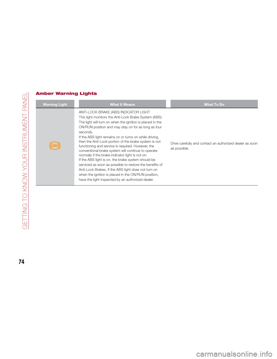
ANTI-LOCK BRAKE (ABS) INDICATOR LIGHT
This light monitors the Anti-Lock Brake System (ABS).
The light will turn on when the ignition is placed in the
ON/RUN position and may stay on for as long as four
seconds.
If the ABS light remains on or turns on while driving,
then the Anti-Lock portion of the brake system is not
functioning and service is required. However, the
conventional brake system will continue to operate
normally if the brake indicator light is not on.
If the ABS light is on, the brake system should be
serviced as soon as possible to restore the benefits of
Anti-Lock Brakes. If the ABS light does not turn on
when the ignition is placed in the ON/RUN position,
have the light inspected by an authorized dealer.Drive carefully and contact an authorized dealer as soon
as possible.
74
GETTING TO KNOW YOUR INSTRUMENT PANEL
Page 83 of 268
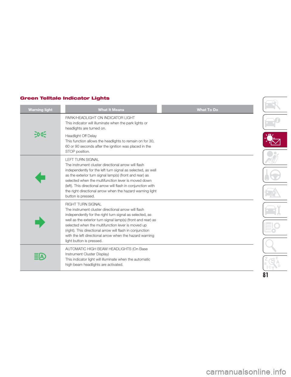
Green Telltale Indicator Lights
Warning lightWhat It Means What To Do
PARK/HEADLIGHT ON INDICATOR LIGHT
This indicator will illuminate when the park lights or
headlights are turned on.
Headlight Off Delay
This function allows the headlights to remain on for 30,
60 or 90 seconds after the ignition was placed in the
STOP position.
LEFT TURN SIGNAL
The instrument cluster directional arrow will flash
independently for the left turn signal as selected, as well
as the exterior turn signal lamp(s) (front and rear) as
selected when the multifunction lever is moved down
(left). This directional arrow will flash in conjunction with
the right directional arrow when the hazard warning light
button is pressed.
RIGHT TURN SIGNAL
The instrument cluster directional arrow will flash
independently for the right turn signal as selected, as
well as the exterior turn signal lamp(s) (front and rear) as
selected when the multifunction lever is moved up
(right). This directional arrow will flash in conjunction
with the left directional arrow when the hazard warning
light button is pressed.
AUTOMATIC HIGH BEAM HEADLIGHTS (On Base
Instrument Cluster Display)
This indicator light will illuminate when the automatic
high beam headlights are activated.
81
Page 84 of 268
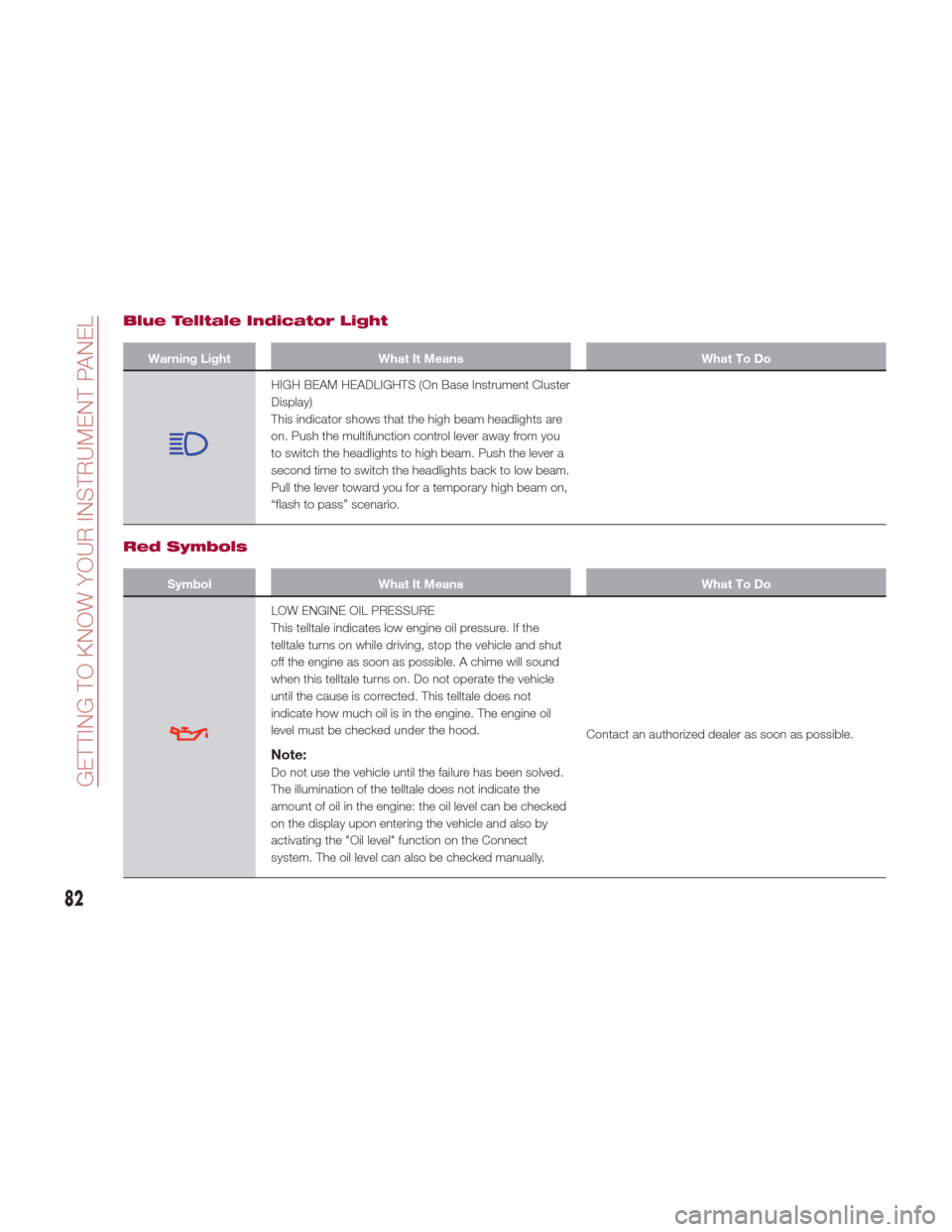
Blue Telltale Indicator Light
Warning LightWhat It Means What To Do
HIGH BEAM HEADLIGHTS (On Base Instrument Cluster
Display)
This indicator shows that the high beam headlights are
on. Push the multifunction control lever away from you
to switch the headlights to high beam. Push the lever a
second time to switch the headlights back to low beam.
Pull the lever toward you for a temporary high beam on,
“flash to pass” scenario.
Red Symbols
SymbolWhat It Means What To Do
LOW ENGINE OIL PRESSURE
This telltale indicates low engine oil pressure. If the
telltale turns on while driving, stop the vehicle and shut
off the engine as soon as possible. A chime will sound
when this telltale turns on. Do not operate the vehicle
until the cause is corrected. This telltale does not
indicate how much oil is in the engine. The engine oil
level must be checked under the hood.
Note:
Do not use the vehicle until the failure has been solved.
The illumination of the telltale does not indicate the
amount of oil in the engine: the oil level can be checked
on the display upon entering the vehicle and also by
activating the "Oil level" function on the Connect
system. The oil level can also be checked manually.Contact an authorized dealer as soon as possible.
82
GETTING TO KNOW YOUR INSTRUMENT PANEL
Page 87 of 268
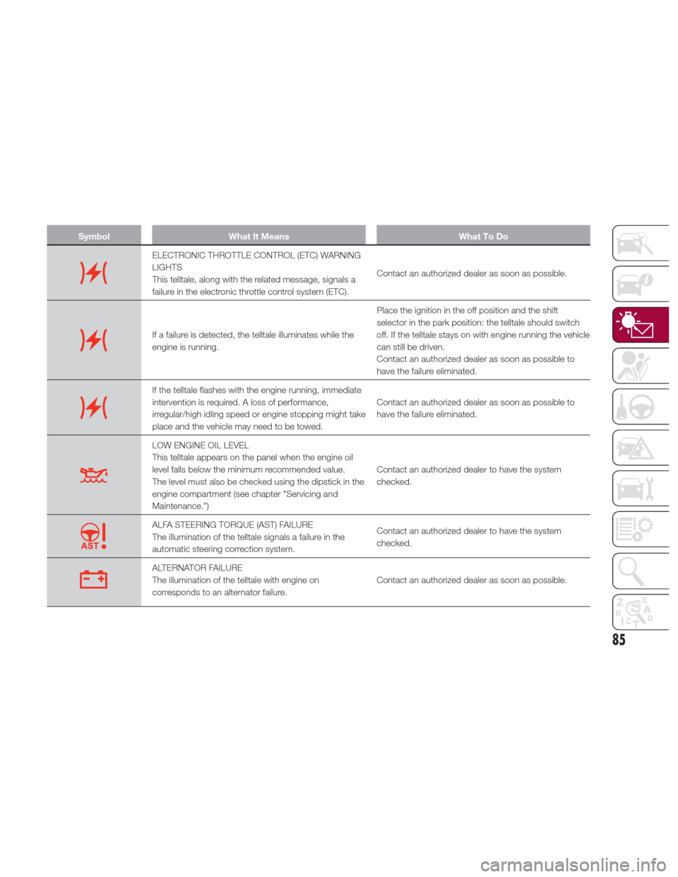
SymbolWhat It Means What To Do
ELECTRONIC THROTTLE CONTROL (ETC) WARNING
LIGHTS
This telltale, along with the related message, signals a
failure in the electronic throttle control system (ETC).Contact an authorized dealer as soon as possible.
If a failure is detected, the telltale illuminates while the
engine is running.Place the ignition in the off position and the shift
selector in the park position: the telltale should switch
off. If the telltale stays on with engine running the vehicle
can still be driven.
Contact an authorized dealer as soon as possible to
have the failure eliminated.
If the telltale flashes with the engine running, immediate
intervention is required. A loss of performance,
irregular/high idling speed or engine stopping might take
place and the vehicle may need to be towed.
Contact an authorized dealer as soon as possible to
have the failure eliminated.
LOW ENGINE OIL LEVEL
This telltale appears on the panel when the engine oil
level falls below the minimum recommended value.
The level must also be checked using the dipstick in the
engine compartment (see chapter "Servicing and
Maintenance.")Contact an authorized dealer to have the system
checked.
ALFA STEERING TORQUE (AST) FAILURE
The illumination of the telltale signals a failure in the
automatic steering correction system.
Contact an authorized dealer to have the system
checked.
ALTERNATOR FAILURE
The illumination of the telltale with engine on
corresponds to an alternator failure.
Contact an authorized dealer as soon as possible.
85
Page 91 of 268
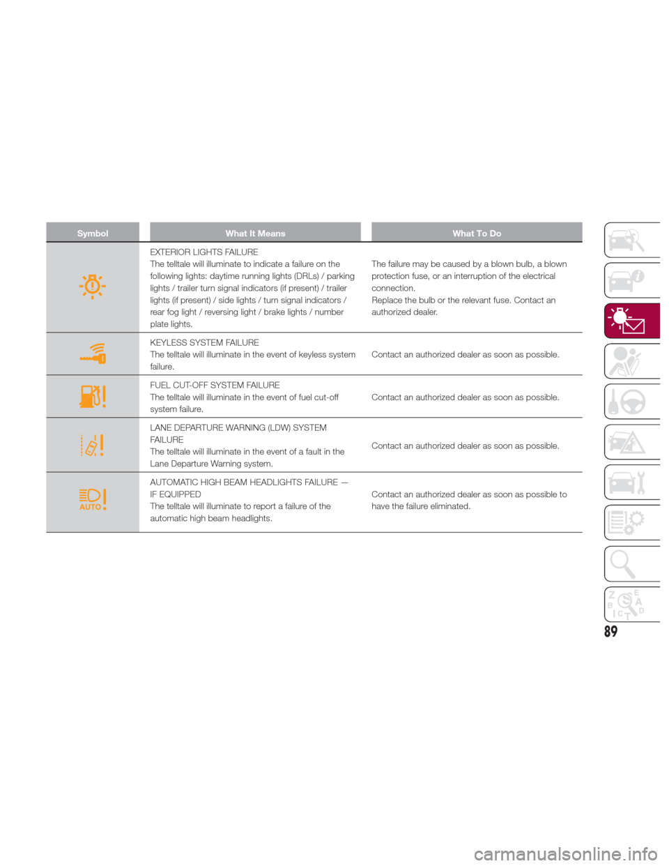
SymbolWhat It Means What To Do
EXTERIOR LIGHTS FAILURE
The telltale will illuminate to indicate a failure on the
following lights: daytime running lights (DRLs) / parking
lights / trailer turn signal indicators (if present) / trailer
lights (if present) / side lights / turn signal indicators /
rear fog light / reversing light / brake lights / number
plate lights.The failure may be caused by a blown bulb, a blown
protection fuse, or an interruption of the electrical
connection.
Replace the bulb or the relevant fuse. Contact an
authorized dealer.
KEYLESS SYSTEM FAILURE
The telltale will illuminate in the event of keyless system
failure.
Contact an authorized dealer as soon as possible.
FUEL CUT-OFF SYSTEM FAILURE
The telltale will illuminate in the event of fuel cut-off
system failure.Contact an authorized dealer as soon as possible.
LANE DEPARTURE WARNING (LDW) SYSTEM
FAILURE
The telltale will illuminate in the event of a fault in the
Lane Departure Warning system.Contact an authorized dealer as soon as possible.
AUTOMATIC HIGH BEAM HEADLIGHTS FAILURE —
IF EQUIPPED
The telltale will illuminate to report a failure of the
automatic high beam headlights.Contact an authorized dealer as soon as possible to
have the failure eliminated.
89
Page 96 of 268
ONBOARD
DIAGNOSTIC
SYSTEM
Operation
The OBD (On Board Diagnostic system)
carries out a continuous diagnosis of
the components of the vehicle related
to emissions.
It also alerts the driver of when these
components are no longer in peak
condition by switching on the
warning light on the instrument
panel (see “Warning Lights And
Messages” paragraph in this chapter).
The aim of the OBD system (On Board
Diagnostic) is to:
Monitor the efficiency of the system
Indicate an increase in emissions
Indicate the need to replace
damaged components The vehicle also has a connector, which
can interface with appropriate tools,
that makes it possible to read the error
codes stored in the electronic control
units together with a series of specific
parameters for engine operation and
diagnosis. This check can be carried
out by your authorized dealer.
Note:
After eliminating a fault, to check
the system completely, your authorized
dealer is obliged to run tests and, if
necessary certain road tests.
Onboard Diagnostic
System (OBD II)
Cybersecurity
Your vehicle is required to have an
Onboard Diagnostic system (OBD II)
and a connection port to allow access
to information related to the
performance of your emissions
controls. Authorized service technicians
may need to access this information to
assist with the diagnosis and service of
your vehicle and emissions system.
Warning!
ONLY an authorized service technician
should connect equipment to the OBD II
connection port in order to diagnose or
service your vehicle.
If unauthorized equipment is connected
to the OBD II connection port, such as a
driver-behavior tracking device, it may:
Be possible that vehicle systems,
including safety related systems, could be
impaired or a loss of vehicle control could
occur that may result in an accident
involving serious injury or death.
Access, or allow others to access,
information stored in your vehicle systems,
including personal information.
94
GETTING TO KNOW YOUR INSTRUMENT PANEL
Page 103 of 268
Rear View
The system detects vehicles coming
from the rear part of your vehicle on
both sides and entering the rear
detection area with a difference in
speed of less than 31 mph (50 km/h)
with relation to your vehicle.
Overtaking Vehicles
If another vehicle is overtaken slowly,
with a difference in speed of less than
approximately 15 mph (25 km/h) and
the vehicle stays in the blind spot for
approximately 1.5 seconds, the
warning light on the door mirror of the
corresponding side lights up.
If the difference in speed between the
two vehicles is greater than
approximately 15 mph (25 km/h), the
warning light does not light up.
Rear Cross Path Detection (RCP)
System
This system helps the driver during
reverse maneuvers in the case of
reduced visibility.
The RCP system monitors the rear
detection areas on both sides of the
vehicle to detect objects moving
towards the sides of the vehicle, with a
minimum speed between approximately
1 mph (1 km/h) and 2 mph (3 km/h)
and objects moving at a maximum
speed of 21 mph (35 km/h), in areas
such as parking lots.
The system activation is signaled to the
driver by a visual and acoustic warning.Note:
If the sensors are covered by
objects or vehicles, the system will not
warn the driver.
Warning!
Rear Cross Path Detection (RCP) is not a
back up aid system. It is intended to be
used to help a driver detect an oncoming
vehicle in a parking lot situation. Drivers
must be careful when backing up, even
when using RCP. Always check carefully
behind your vehicle, look behind you, and
be sure to check for pedestrians, animals,
other vehicles, obstructions, and blind
spots before backing up. Failure to do so
can result in serious injury or death.
Operating Mode
The system may be activated/
deactivated via the Connect system. To
access the function, select the following
items on the main menu in sequence:
"Settings", "Safety" and "Blind Spot
Alert".
"Blind Spot Alert", "Visual" Mode
When the system is enabled, a visual
warning is sent to the door mirror on
the side of the detected object.
The visual warning on the mirror will
blink if the driver switches on the
direction indicators, thus indicating the
intention to change lane.
The warning will be fixed if the driver
stays in the same lane. "Blind Spot Alert" Function
Deactivation
When the system is deactivated ("Blind
Spot Alert" mode off), the BSM or RCP
systems will not emit either acoustic or
visual warnings.
The BSM system will store the
operating mode running when the
engine was stopped. Each time the
engine is started, the operating mode
stored previously will be recalled and
used.
General Information
This vehicle has systems that operate
on radio frequency that comply with
Part 15 of the Federal Communications
Commission (FCC) rules and with
Industry Canada Standards RSS-
GEN/210/220/310.
Operation is subject to the following
two conditions:
1. The device may not cause harmful
interference.
2. The device must accept any
interference received, including
interference that may cause undesired
operation of the device.
Changes or modifications to any of
these systems by other than an
authorized service facility could void
authorization to use this equipment.
101