clock Alfa Romeo GT 2005 Owner handbook (in English)
[x] Cancel search | Manufacturer: ALFA ROMEO, Model Year: 2005, Model line: GT, Model: Alfa Romeo GT 2005Pages: 307, PDF Size: 6.05 MB
Page 118 of 307

GETTING TO KNOW YOUR CAR
116
FAN SPEED ADJUSTMENT
KNOB
(fig. 105-106)
Turning the ring of knob(4), clockwise or
counter-clockwise, increases or decreases
the speed of the fan, thus the amount of air
admitted to the passenger compartment;
the 16 selectable speeds are shown on a
bar (in steps of 3), up to a maximum of 6
bars lit:
- maximum fan speed = all bars lit;
- minimum fan speed = one bar lit.
The fan can be cut off (all bars off) only
if the climate control compressor has been
switched off pressing button (14)
√. To
restore automatic fan speed control, after a
manual adjustment, press button (13)
AU-
TO. Completely turning the ring of knob (4)
counter-clockwise switches the system off,
with the following situation: display (1) off;
display (5) off; centre display (3) with lit-
display
OFFand left led on inside air re-cir-
culation button (8)
von.
IMPORTANTPressing the inside air re-
circulation button (8)
vit is possible to
obtain the inlet of untreated outside air to
the passenger compartment.
To turn the system on again, simply turn
the ring of knob (4) clockwise, or press any
one button, except the inside air re-circula-
tion (8) and rearscreen (9) buttons; this
operation restores all the operating conditionsstored previously.
IMPORTANTOn leaving the
OFFcondi-
tion, inside air re-circulation
vreturns to
the condition prior to switching off.
A0A0205b
A0A0206bfig. 105
fig. 106
Page 201 of 307

GETTING TO KNOW YOUR CAR
199
ENVIRONMENTAL
PROTECTION
The devices used to reduce petrol engine
emissions are:
– trivalent catalytic converter (catalytic si-
lencer);
– Lambda sensors;
– anti-evaporation system.
If one or more spark plugs are discon-
nected, do not run the engine, even for a
test.
The devices used to reduce diesel fuel en-
gine emissions are:
– oxidising catalyst;
– exhaust gas re-circulation system
(E. G. R.). Do not go near the fuel
filler with naked flames or
lit cigarettes: danger of
fire. Avoid going too near the fuel
filler with your face, to avoid in-
haling harmful vapours.
In the case of need, only
replace the fuel cap with
another genuine one, or the
efficiency of the fuel vapour re-
covery system could be adversely
affected.
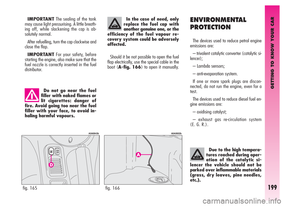
Should it be not possible to open the fuel
flap electrically, use the special cable in the
boot (A-fig. 166) to open it manually.
Due to the high tempera-
tures reached during oper-
ation of the catalytic si-
lencer the vehicle should not be
parked over inflammable materials
(grass, dry leaves, pine needles,
etc.).
fig. 165
A0A0643b
fig. 166
A0A0652b
IMPORTANTThe sealing of the tank
may cause light pressurising. A little breath-
ing off, while slackening the cap is ab-
solutely normal.
After refuelling, turn the cap clockwise and
close the flap.
IMPORTANTFor your safety, before
starting the engine, also make sure that the
fuel nozzle is correctly inserted in the fuel
distributor.
Page 224 of 307

IN AN EMERGENCY
222
CYLINDER REPLACEMENT
PROCEDURE
To replace the cylinder proceed as follows:
– disconnect connection A-fig. 20and
hoseB;
– turn counter-clockwise the cylinder to re-
place and raise it;– fit the new cylinder and turn it clockwise;
– refit connection Aor connect hose Bin-
to its seat.Inform other people dri-
ving the car that the tyre
has been repaired using the
quick tyre kit. Hand the sticker to
the personnel that will carry out
restoring operations.
fig. 20
A0A01103b
Page 226 of 307

IN AN EMERGENCY
224
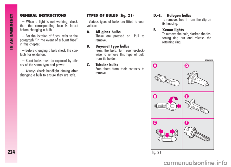
D.-E. Halogen bulbs
To remove, free it from the clip on
its housing.
F. Xenon lights
To remove the bulb, slacken the fas-
tening ring nut and release the
retaining ring. GENERAL INSTRUCTIONS
– When a light is not working, check
that the corresponding fuse is intact
before changing a bulb.
– For the location of fuses, refer to the
paragraph “In the event of a burnt fuse”
in this chapter.
– Before changing a bulb check the con-
tacts for oxidation.
– Burnt bulbs must be replaced by oth-
ers of the same type and power.
– Always check headlight aiming after
changing a bulb to ensure they are safe.
TYPES OF BULBS (fig. 21)
Various types of bulbs are fitted to your
vehicle:
A. All glass bulbs
These are pressed on. Pull to
remove.
B. Bayonet type bulbs
Press the bulb, turn counter-clock-
wise to remove this type of bulb
from its holder.
C. Tubular bulbs
Free them from their contacts to
remove.
fig. 21
A0A0503b
Page 228 of 307

IN AN EMERGENCY
226
IF AN EXTERIOR
LIGHT GOES OUT
XENON LIGHTS
Due to high voltage, the
bulb of (Xenon) gas-dis-
charge headlights must on-
ly be replaced by experts: danger
of death! Contact Alfa Romeo Au-
thorized Services.
HALOGEN HEADLIGHTSThe bulbs are arranged inside the light
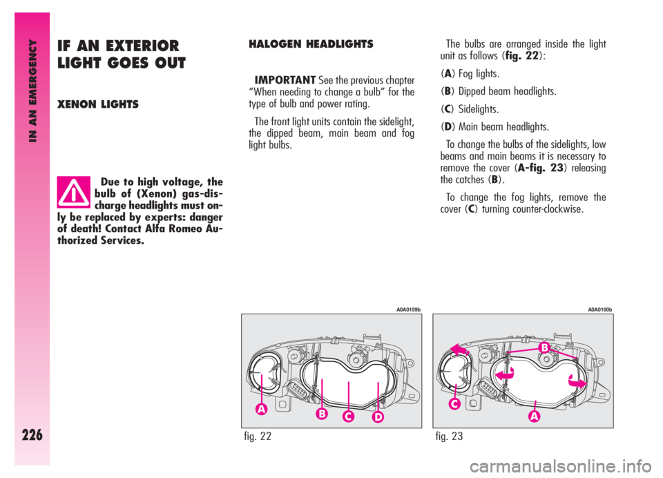
unit as follows (fig. 22):
(A) Fog lights.
(B) Dipped beam headlights.
(C) Sidelights.
(D) Main beam headlights.
To change the bulbs of the sidelights, low
beams and main beams it is necessary to
remove the cover (A-fig. 23) releasing
the catches (B).
To change the fog lights, remove the
cover (C) turning counter-clockwise. IMPORTANTSee the previous chapter
“When needing to change a bulb” for the
type of bulb and power rating.
The front light units contain the sidelight,
the dipped beam, main beam and fog
light bulbs.
fig. 22
A0A0159b
fig. 23
A0A0160b
Page 229 of 307

IN AN EMERGENCY
227
– Fit a new bulb, making the tab of the
metal part coincide with the one on the
lamp unit, then hook the bulb holder catch
(B).
– Re-connect the electric connector (A).
– Refit the protective cover correctly.Fog lights (fig. 24)
IMPORTANTWhen needing to
change the left bulb, the side trim next to
the light itself needs to be removed to
facilitate access to the engine compart-
ment.
To change the bulb, proceed as follows:
– Remove the protective cover turning
counter-clockwise.
– Disconnect the electric connector (A).
– Release the bulb catch (B).
– Remove the bulb and replace it.
fig. 24
A0A0161b
After replacement, refit
the covers correctly
checking that they are
properly secured.
IMPORTANTA slight layer of steam
(fogging) can appear on the inside surface
of the beam transparent cover: this is not
a defect. The presence of condensate
traces in beams is a natural phenomenon,
due to a low temperature and to the
degree of humidity in the air. These traces
will disappear when the beams are turned
on. Drops of water inside the headlight
indicate instead water infiltration: contact
Alfa Romeo Authorised Services.
Page 230 of 307

IN AN EMERGENCY
228
Dipped beam headlights
(fig. 25)
To change the bulb, proceed as follows:
– Remove the protective cover releasing
the catches.
– Disconnect the electric connector (A).
– Release the bulb catch (B).
– Remove the bulb and replace it.
– Fit a new bulb, making the tabs of the
metallic part coincide with the grooves on
the reflector, then hook the bulb holder
catch (B).
– Re-connect the electric connector (A).
– Refit the protective cover correctly.
fig. 25
A0A0162b
Main beam headlights
(fig. 27)
To change the bulb, proceed as follows:
– Remove the protective cover releasing
the catches.
– Disconnect the electric connector (A).
– Release the bulb catch (B).
– Remove the bulb and replace it.
– Fit a new bulb, making the tabs of the
metallic part coincide with the grooves on
the reflector, then hook the bulb holder
catch (B).
– Re-connect the electric connector (A).
– Refit the protective cover correctly.
fig. 27
A0A0164b
Front side lights(fig. 26)
To change the bulb, proceed as follows:
– Remove the protective cover releasing
the catches.
– Using the extension (A), integral with
the bulb holder (B), withdraw the bulb
holder itself which is snap-fitted.
– Remove the bulb (C), pushing gently
and turning counter-clockwise.
– Change the bulb and re-insert the bulb
holder making sure that it clicks into
place; also check that the bulb is in the
correct position looking at the lamp from
outside.
– Refit the protective cover correctly.
fig. 26
A0A0342b
Page 231 of 307

IN AN EMERGENCY
229
– Replace the bulb;
– Refit the bulb holder turning counter-
clockwise and check that it is secured cor-
rectly;
– Refit the transparent.SIDE DIRECTION INDICATORS
(fig. 30)
– Push the transparent cover towards
the rear of the car to compress the catch
(A). Release the front part and remove
this unit.
– Turn the bulb holder (B) counter-clock-
wise and remove it from the cover.
– Remove the snap-fitted bulb and
replace it.
– Insert the bulb holder (B) in the trans-
parent cover, then position the unit mak-
ing sure the catch clicks into place (A).
fig. 29
A0A0626b
fig. 30
A0A0166b
FRONT DIRECTION
INDICATORS
(fig. 28-29)
To change the bulb, proceed as follows:
– Using the screwdriver provided,
remove the transparent unit operating on
the two metal clips as shown in the figure;
– Turn the bulb holder clockwise (A)
and remove it;
– Remove the bulb (B) pushing gently
and turning counter-clockwise;
fig. 28
A0A0625b
Page 232 of 307

IN AN EMERGENCY
230
REVERSING LIGHT
AND REAR FOG GUARDS
(fig. 31-32)
The reversing light and rear fog guard are
in the tail light unit fastened to the tailgate;
they are to be found respectively one on the
right and the other on the left of the vehicle
facing forwards.
To change the bulb, proceed as follows:
– from the bumper lower side (fig. 31),
operate on the bulb holder (A-fig 32) turn-
ing it counter-clockwise and remove it. Take
care not to get burnt if the muffler is still hot;
fig. 31
A0A0627b
fig. 33
A0A0629b
– Remove the bulb pushing gently and
turning counter-clockwise;
– Replace the bulb, then refit the bulb
holder.
Anyway, you are advised to have this
operation carried out by Alfa Romeo
Authorised Services.REAR DIRECTION INDICATORS
AND REAR SIDELIGHTS-
BRAKING LIGHTS
(fig. 33-34)
The rear direction indicators and the side-
lights-braking lights are in the tail light
unit fastened to the body.
To change the bulb, proceed as follows:
– From inside the boot, open the com-
partment (A-fig. 33) and then the door
(B) through the tab (C);
– Turn the bulb for sidelight and braking
light counter-clockwise (D-fig. 34),
or the bulb for the direction indicator (E-
fig. 34) and remove it;
fig. 32
A0A0628b
Page 233 of 307

IN AN EMERGENCY
231
NUMBER PLATE LIGHTS
(fig. 35)
To change the bulbs, proceed as follows:
– Work on the transparent cover frame,
in the point shown by the arrow to com-
press the catch (B). Free the opposite end
and remove the unit.
– Turn the bulb holder counter-clockwise
(A) and remove it from the transparent
cover.
– Remove the snap-fitted bulb and
replace it.
– Insert the bulb holder (A) in the trans-
parent cover then refit the unit checking
that the catch clicks into place (B).
ADDITIONAL BRAKING LIGHT
(THIRD STOP)
(fig. 36-37)
To change the led unit, proceed as fol-
lows:
– Open the tailgate and use a screwdriv-
er to open the two covers (A-fig. 36);
– Slacken the two fastening screws of
(B) the led unit;
fig. 35
A0A0171b
fig. 36
A0A0631b
A0A0630b
– Withdraw the light (ForG) push it
gently and turn counter-clockwise;
– Replace the bulb;
– Refit the bulb holder turning clockwise
and make sure it is secured correctly;
– Refit the door (B) and close the com-
partment (A).
fig. 34