steering Alfa Romeo GT 2005 Owner handbook (in English)
[x] Cancel search | Manufacturer: ALFA ROMEO, Model Year: 2005, Model line: GT, Model: Alfa Romeo GT 2005Pages: 307, PDF Size: 6.05 MB
Page 134 of 307

GETTING TO KNOW YOUR CAR
132
This should not be considered a failure be-
cause it is part of the operating logic. For
the same reason, if sticking occurs on re-
verse gear, the system controls partial clutch
closing so that the gear can be engaged;
in this case the engagement of reverse gear
(R) will not be as smooth as usual.
Moving off the car is obtained:
1) releasing the brake pedal;
2) gradually pressing the accelerator pedal.
The more the accelerator is pressed the
higher the pickup torque.
After a request to shift
gear with the car station-
ary, before pressing the ac-
celerator pedal to make the car
move, the driver must always
check the display to see that the
gear engaged is the one required.MOVING OFF THE CAR
With the engine on and the car stationary,
the gears that can be engaged for moving
off are only first (1), second (2) or reverse
(R).
To engage them, keep the brake pedal de-
pressed and operate only the control lever
on the central console, as the steering wheel
levers make it possible to engage the gears
only at speed over 0.5 km/h.
IMPORTANTReverse gear (R) can be
engaged from any of the following other ra-
tios: neutral (N), first (1) or second (2).
If the car is moving, the request is not ac-
cepted, it is necessary to wait for the car
to stop completely and request the en-
gagement of reverse again (R).
The driver is informed of the reverse gear
engaged condition by the display and by the
intermittent sound of a buzzer.
IMPORTANTIf when shifting from re-
verse (R)/first (1) or neutral (N)/first (1)
sticking occurs on first gear, the system au-
tomatically engages second gear (2).IMPORTANTS
– With the car stopped and a gear en-
gaged always keep the brake pedal pressed
until deciding to move off;
– during prolonged halts with the engine
running it is advisable to keep the gearbox
in neutral;
– when the car is parked facing uphill, do
not use the moving off manoeuvre to keep
the car still; use the brake pedal and press
the accelerator pedal only when deciding to
move off;
– use second gear only when more con-
trol is needed for moving off manoeuvres at
low speed;
– if, in reverse gear, first gear is engaged
or vice versa, shift gear only when the car
is stopped completely and with the brake
pedal pressed.
Though highly unadvisable, if when trav-
elling downhill for some unexpected reason
the car is set to neutral (N), when the en-
gagement of a gear is requested the system
automatically engages the best gear in re-
lation to the speed of the car to allow the
correct transmission of torque to the wheels.
Page 136 of 307

GETTING TO KNOW YOUR CAR
134
SEMIAUTOMATIC OPERATION
(MANUAL)
In the MANUAL operating mode, the dis-
play shows the gear engaged.
In this operating mode, the decision to
change gear is left to the driver who decides
the most appropriate moment.The requests to change gear may take
place through:
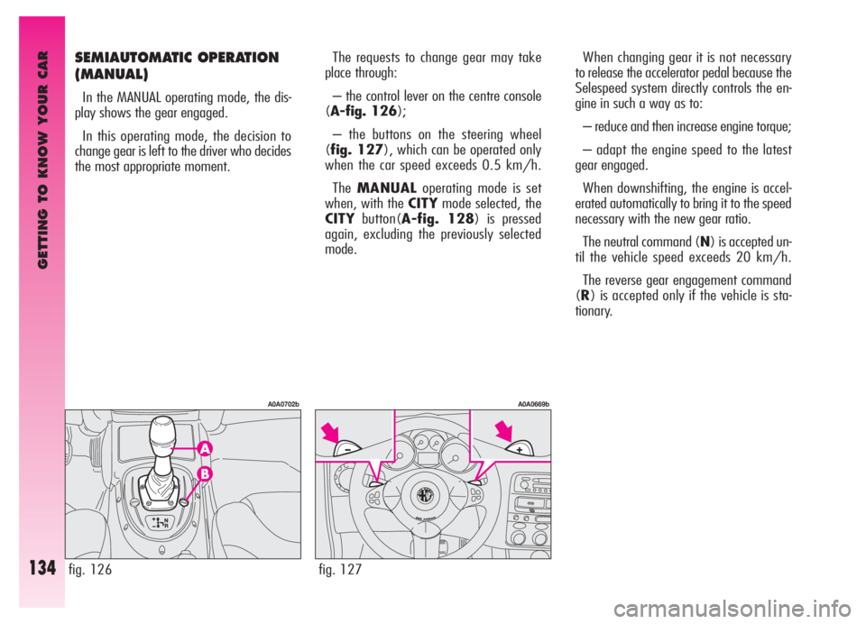
– the control lever on the centre console
(A-fig. 126);
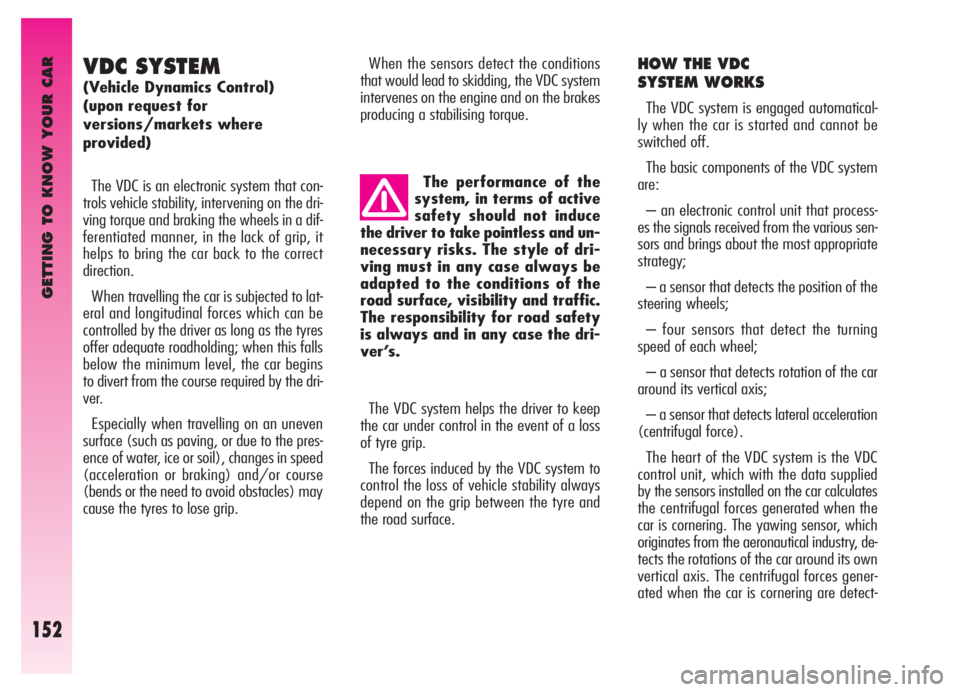
– the buttons on the steering wheel
(fig. 127), which can be operated only
when the car speed exceeds 0.5 km/h.
TheMANUALoperating mode is set
when, with the CITYmode selected, the
CITYbutton(A-fig. 128) is pressed
again, excluding the previously selected
mode.When changing gear it is not necessary
to release the accelerator pedal because the
Selespeed system directly controls the en-
gine in such a way as to:
– reduce and then increase engine torque;
– adapt the engine speed to the latest
gear engaged.
When downshifting, the engine is accel-
erated automatically to bring it to the speed
necessary with the new gear ratio.
The neutral command (N) is accepted un-
til the vehicle speed exceeds 20 km/h.
The reverse gear engagement command
(R) is accepted only if the vehicle is sta-
tionary.
fig. 127
A0A0669b
fig. 126
A0A0702b
Page 150 of 307

GETTING TO KNOW YOUR CAR
148
Scarves, ties and other
loose clothing might be
pulled by moving parts.
For safety reasons the
bonnet shall always be
perfectly closed when trav-
elling. Always check for proper
bonnet locking. If the bonnet is left
inadvertently open, stop the car
immediately and close the bonnet.
To close:
– lower the bonnet until approx. 20 cm
from the engine compartment and then let
it drop, ensuring it is fully closed and not just
held in position by the safety catch.
If the bonnet does not close properly do
not push it down but open it again and re-
peat the above procedure.
HEADLIGHTS
The adjustment of the headlights is vital to
your safety and comfort and to that of oth-
er road users.
The adjustment of the headlights is also
governed by precise regulations.
Contact Alfa Romeo Authorised Services to
have the headlights correctly adjusted.
IMPORTANTThe headlight inner sur-
face may get slightly misted: this does not
mean it is faulty; it is a natural phenome-
non due to low temperature and the air hu-
midity level. Misting will disappear as soon
as the headlights are turned on. The pres-
ence of water drops inside the headlight in-
dicates water infiltration: contact Alfa Romeo
Authorised Services.
COMPENSATION FOR TILT
(fig. 150)
When the vehicle is loaded, the beam from
the headlights is raised due to the back-
wards tilt of the vehicle.
In this case the headlights must be ad-
justed correctly.
To do this, use the rocker button (A), on
the plate at the side of the steering column:
– press the arrow on the button (
A), to
increase by one position (e.g.:0
➟1➟2➟
3);
– press the arrow on the button (
S), this will low-
er by one position (e.g.:3
➟2➟1➟0);
The display (B) in the tachometer shows
the positions while adjustment is being ma
fig. 150
A0A0093b
Page 154 of 307

GETTING TO KNOW YOUR CAR
152
VDC SYSTEM
(Vehicle Dynamics Control)
(upon request for
versions/markets where
provided)
The VDC is an electronic system that con-
trols vehicle stability, intervening on the dri-
ving torque and braking the wheels in a dif-
ferentiated manner, in the lack of grip, it
helps to bring the car back to the correct
direction.
When travelling the car is subjected to lat-
eral and longitudinal forces which can be
controlled by the driver as long as the tyres
offer adequate roadholding; when this falls
below the minimum level, the car begins
to divert from the course required by the dri-
ver.
Especially when travelling on an uneven
surface (such as paving, or due to the pres-
ence of water, ice or soil), changes in speed
(acceleration or braking) and/or course
(bends or the need to avoid obstacles) may
cause the tyres to lose grip.When the sensors detect the conditions
that would lead to skidding, the VDC system
intervenes on the engine and on the brakes
producing a stabilising torque.
HOW THE VDC
SYSTEM WORKS
The VDC system is engaged automatical-
ly when the car is started and cannot be
switched off.
The basic components of the VDC system
are:
– an electronic control unit that process-
es the signals received from the various sen-
sors and brings about the most appropriate
strategy;
– a sensor that detects the position of the
steering wheels;
– four sensors that detect the turning
speed of each wheel;
– a sensor that detects rotation of the car
around its vertical axis;
– a sensor that detects lateral acceleration
(centrifugal force).
The heart of the VDC system is the VDC
control unit, which with the data supplied
by the sensors installed on the car calculates
the centrifugal forces generated when the
car is cornering. The yawing sensor, which
originates from the aeronautical industry, de-
tects the rotations of the car around its own
vertical axis. The centrifugal forces gener-
ated when the car is cornering are detect- The performance of the
system, in terms of active
safety should not induce
the driver to take pointless and un-
necessary risks. The style of dri-
ving must in any case always be
adapted to the conditions of the
road surface, visibility and traffic.
The responsibility for road safety
is always and in any case the dri-
ver’s.
The VDC system helps the driver to keep
the car under control in the event of a loss
of tyre grip.
The forces induced by the VDC system to
control the loss of vehicle stability always
depend on the grip between the tyre and
the road surface.
Page 155 of 307

GETTING TO KNOW YOUR CAR
153
ed by a highly sensitive lateral acceleration
sensor.
The stabilising action of the VDC system is
based on the calculations of the system elec-
tronic control unit, which processes the sig-
nals received from the steering wheel rota-
tion sensor, acceleration sensor and rotation
speed sensor of each wheel. These signals
allow the control unit to recognise the ma-
noeuvre the driver intends to do when the
steering wheel is turned.
The control unit processes the information
received from the sensors and therefore is
able to know the position of the car instant
by instant and compares it with the course
the driver would like to follow. In the event
of a discrepancy, in a fraction of a second
the control unit chooses and commands the
most suitable intervention to bring the car
immediately back to the required course:
braking one or more wheels at different in-
tensity and, if necessary, reducing the pow-
er transmitted by the engine.
The corrective actions are modified and
controlled continuously in seeking the course
required by the driver.
The action of VDC system considerably en-
hances the active safety of the car in very
critical situations and it is particularly help-
ful when the grip conditions of the road sur-
face change.For the VDC system to
work correctly, the tyres
must be of the same brand
and type on all wheels, in perfect
conditions and above all of the
specified type, brand and size.CUTTING IN
OF THE VDC SYSTEM
The cutting in of the VDC system is indi-
cated by the flashing of the
áwarning light
on the instrument cluster, to inform the dri-
ver that the car is in critical conditions of sta-
bility and grip.
VDC system
failure warning
In the event of a failure the VDC system
disengages automatically and the
áwarn-
ing light on the instrument cluster turns on
glowing steadily, together with the message
on the reconfigurable multifunction display.
In the event of an VDC system failure the
car behaves like a vehicle not fitted with this
system: in any case it is advisable to con-
tact Alfa Romeo Authorised Services as soon
as possible.During use of the compact
spare wheel, the VDC sys-
tem continues working. It
should be borne in mind that the
spare wheel is smaller than a nor-
mal tyre, therefore its grip is low-
er than that of the other tyres of
the car.
Page 166 of 307

GETTING TO KNOW YOUR CAR
164
11. 5-MIXFunction select button:
– Call station no. 5
– Store station no. 5
– Random CD track playing
12. 4-RPTFunction select button:
– Call station no. 4
– Store station no. 4
– Continuous CD track playing
13. BN-ASRadio frequency range select
function (FM1, FM2, FMT,
MW, LW) - Autostore
14. SRC-SCOperating mode select button
Radio - Compact Disc - CD-
Changer and Scan function
(hearing stations in se-
quence)
15. 3-IIFunction select button:
– Call station no. 3
– Store station no. 3
– CD playing pause
16. 2-CLRFunction select button:
– Call station no. 2
– Store station no. 2
– CLR function (CD track stor-
age clearing)17. 1-TPMFunction select button:
– Call station no. 1
– Store station no. 1
– TPM function (storing CD
playing sequence)
18. AUD-LDSound function select button:
bass tones, treble tones,
right/left and front/rear bal-
ancing and Loudness (ex-
cluding versions with HI-FI
BOSE sound system)
19. VOL-Volume lowering button
20. ON-
zFunction select button:
– Set on/off
– Mute on/off
21. VOL+Volume highering button
CONTROLS ON THE STEERING
WHEEL
(fig. 155)
The main radio function controls are re-
peated on the steering wheel, to allow eas-
ier control.
1.Volume increase button
2.Volume decrease button
3.Mute button
4.Radio frequency range select button
(FM1, FM2, FMT, MW, LW) and avail-
able sources (Radio - Compact Disc - CD-
Changer)
5.Multifunction button:
– Radio: call preset stations (from 1 to
6)
– Compact Disc player: select next piece
fig. 155
A0A0640b
Page 204 of 307

Never push, tow or
coast start the vehicle.
This could cause fuel to
flow into the catalyst damaging
it irreversibly.
Remember that the
engine brake and power
steering are not opera-
tional until the engine is started,
therefore, much greater effort
than usual is needed on the brake
pedal and steering wheel.CORRECT USE OF THE CAR
202
For cars with tur-
bocharger in particular,
but for all cars in general,
sharp accelerating should be
avoided before switching the
engine off.
A “kick” on the accelerator
serves no purpose, consumes fuel
pointlessly and may cause seri-
ous damage to the turbocharger
impeller bearings.EMERGENCY STARTING
If the Alfa Romeo CODE system does not
recognise the code transmitted by the igni-
tion key (warning light
Yon the instru-
ment cluster glowing on steadily) emer-
gency starting may be carried out using
the code of the CODE card.
For the correct procedure see the chapter
“In an emergency”.
IMPORTANTIf the engine turns off
with the vehicle on the move, the next
time it is started, the Alfa Romeo CODE
warning light may turn on(
Y). In this
case, check that switching off and starting
the engine again with the vehicle station-
ary, the warning light stays off. If not, con-
tact Alfa Romeo Authorised Services.
ENGINE SWITCHING OFF
– Release the accelerator pedal and wait
until the engine reaches idle speed.
– Turn the ignition key to the STOP
position and switch off the engine.
IMPORTANTAfter a tiring journey it is
advisable to let the engine “get its breath
back” allowing it to idle a while to lower
the temperature in the engine compart-
ment.
Page 211 of 307

CORRECT USE OF THE CAR
209
Keep your speed
down when snow
chains are fitted.
Do not exceed 50 km/h. Avoid
potholes, steps and pavements to
prevent damaging the tyres, sus-
pension and steering. Remember
that with snow chains fitted the
brake distance will increase.
VEHICLE INACTIVITY
If the vehicle is to be left inactive for
long periods, the following precautions
should be noted:
– House the vehicle under cover in a dry
and possibly ventilated place.
– Engage a gear.
– Check that the handbrake is not
engaged.
– Clean and protect the paintwork by
protective wax.
– Cover the rubber windscreen and
rearscreen wiper blades with talcum pow-
der and raise them off the glass.
– Open the windows slightly.
– Inflate the tyres to a pressure of 0.5
bars above normal. If possible rest the
tyres on wooden planks and periodically
check the pressure.
– Do not turn on the electronic alarm
system.– Disconnect the battery negative termi-
nal (–) from the battery and check the
battery charge. This check should be
repeated once a month during stowage.
Charge the battery if the loadless voltage
is below 12,5V.
– Do not empty the engine cooling sys-
tem.
– Cover the vehicle with a fabric or per-
forated plastic cover. Do not use compact
plastic covers which prevent the humidity
on the surface of the vehicle from evapo-
rating. Snow chains cannot be
fitted to the compact
spare wheel. So, if a front
(drive) wheel is punctured and
chains are needed, a rear wheel
should be fitted to the front of
the vehicle (inflate the tyres to
the specified pressure as soon as
possible) and the spare wheel
should be fitted to the rear. This
way, with two normal drive
wheels, snow chains can be fitted
to them to solve an emergency.
With snow chains fitted
it is advisable to turn off
the ASR system. Press
the ASR-OFF button, led on but-
ton on.
Page 214 of 307

IN AN EMERGENCY
212
STARTING BY INERTIA
If the car is equipped with “Kit for tyre
repair Fix&Go“, see the instructions con-
tained in the following chapter.
GENERAL INSTRUCTIONS
As an alternative to FIX & GO, the com-
pact spare wheel or a wheel with the nor-
mal size can be supplied upon request;
wheel changing and correct use of the
jack and compact spare wheel call for
some precautions as listed below.
IN THE EVENT OF A PUNCTURE
Never push, tow or
coast start the vehicle.
This could cause fuel to
flow into the catalyst damaging
it irreversibly.
Remember that the
engine brake and power
steering are not opera-
tional until the engine is started,
therefore, much greater effort
than usual is needed on the brake
pedal and steering wheel.
Signal the presence of
the stationary vehicle
according to current regu-
lations: hazard warning lights,
reflecting triangle etc..
Any passengers should leave
the car and wait for the wheel to
be changed out of harm of the
traffic.
If parked on a slope or rough
surface, chock the wheels with
wedges or other suitable devices
to prevent the car from rolling.
Never start the engine
with the car jacked.
When driving with a
trailer, disconnect the trailer
before raising the car.
The compact spare wheel is spe-
cific to your car, do not use it on
other models, or use the spare
wheel of other models on your
vehicle.
Should the type of wheels used
be changed (alloy rims instead of
steel), it is also necessary to
change the whole set of fastening
bolts with others of suitable size.
The compact spare wheel is nar-
rower than normal wheels, it
should be used only for the dis-
tance necessary to reach a service
point to have the punctured tyre
repaired and, during its use, the
car speed must not exceed 80
km/h.
Page 243 of 307

IN AN EMERGENCY
241
Volumetric sensors
ESP system sensor
Steering angle sensor
EOBD system diagnosis socket
Cell phone provision
Driver’s door control unit supply
Passenger’s door control unit supply
Control lighting
Climate control system control lighting
Instrument cluster
Instrument cluster
Driver’s door control unit
ABS control unit
ABS control unit
Dashboard control unit
Air - bag control unit
Electronic injection control unit +30
Engine compartment control box (petrol versions)
Dashboard control unit
Trailer control unit15
7.5
7.5
15
15
20
20
7.5
7.5
10
10
15
7.5
50
50
7.5
7.5
125
70
10 F39
F42
F42
F39
F39
F47
F48
F49
F35
F37
F53
F39
F42
F04 (MAXI-FUSE)
F02 (MAXI-FUSE)
F50
F18
F70 (MEGA-FUSE)
F71 (MAXI-FUSE)
F36 52
52
52
52
52
52
52
52
52
52
52
52
52
53
53
52
53
54
54
52
SERVICES FIGURE FUSE AMPERES