Alfa Romeo GT 2010 Owner handbook (in English)
Manufacturer: ALFA ROMEO, Model Year: 2010, Model line: GT, Model: Alfa Romeo GT 2010Pages: 271, PDF Size: 5.34 MB
Page 201 of 271

IN AN EMERGENCY
199
REVERSING LIGHT
AND REAR FOG GUARDS
(fig. 31-32)
The reverse light and the rear fog light
(both reverse lights for Mexico version) are
housed inside the light unit secured to the
rear bumper and are located at the bottom
side.
fig. 31
A0A0627b
fig. 33
A0A0629b
To change the bulb, proceed as follows:
– from the bumper lower side (fig. 31),
operate on the bulb holder (A-fig 32) turn-
ing it counter-clockwise and remove it. Take
care not to get burnt if the muffler is still hot;
– Remove the bulb pushing gently and
turning counter-clockwise;
– Replace the bulb, then refit the bulb
holder.
Anyway, you are advised to have this op-
eration carried out by Alfa Romeo Authorised
Services.REAR DIRECTION INDICATORS
AND REAR SIDELIGHTS-
BRAKING LIGHTS
(fig. 33-34)
The rear direction indicators and the side-
lights-braking lights are in the tail light unit
fastened to the body.
To change the bulb, proceed as follows:
– From inside the boot, open the com-
partment (A-fig. 33) and then the door
(B) through the tab (C);
– Turn the bulb for sidelight and braking
light counter-clockwise (D-fig.34), or the
bulb for the direction indicator (E-fig.34)
and remove it;
fig. 32
A0A0628b
Page 202 of 271

IN AN EMERGENCY
200
NUMBER PLATE LIGHTS
(fig. 35)
To change the bulbs, proceed as follows:
– Work on the transparent cover frame,
in the point shown by the arrow to compress
the catch (B). Free the opposite end and re-
move the unit.
– Turn the bulb holder counter-clockwise (A)
and remove it from the transparent cover.
– Remove the snap-fitted bulb and replace it.
– Insert the bulb holder (A) in the trans-
parent cover then refit the unit checking that
the catch clicks into place (B).
ADDITIONAL BRAKING LIGHT
(THIRD STOP)
(fig. 36-37)
To change the led unit, proceed as follows:
– Open the tailgate and use a screwdriv-
er to open the two covers (A-fig. 36);
– Slacken the two fastening screws of (B)
the led unit;
fig. 35
A0A0171b
fig. 36
A0A0631b
A0A0630b
– Withdraw the light (ForG) push it gen-
tly and turn counter-clockwise;
– Replace the bulb;
– Refit the bulb holder turning clockwise
and make sure it is secured correctly;
– Refit the door (B) and close the com-
partment (A).
fig. 34
Page 203 of 271

IN AN EMERGENCY
201
– disconnect the connector (C-fig. 37),
remove the led unit (D) and replace it with
a new unit;
– Refit the unit on the tailgate reversing
the above mentioned procedure.
fig. 37
A0A0632b
fig. 39
A0A0175b
PUDDLE LIGHTS (fig. 38)
(per versions/market where
provided)
To change the bulb, proceed as follows:
– Open the door and slacken the screw
(A) fastening the transparent covers.
– Remove the unit composed of the two
transparent covers then change the bulb, re-
leasing it from the side contacts making sure
that the new bulb is correctly clamped be-
tween the contacts.
– Realign the two transparent covers and
tighten the fastening screw (A).IF AN INTERIOR
LIGHT GOES OUT
FRONT ROOF LIGHT
(fig. 39-40)
To change the bulbs, proceed as follows:
– Remove the light unit (A) levering in
the points shown by the arrow (in corre-
spondence with the retainer catches).
– Open the protective cover (B).
– Replace the bulb concerned releasing it
from the side contacts making sure that the
new bulb is correctly clamped between the
contacts.
fig. 38
A0A0174b
Page 204 of 271

IN AN EMERGENCY
202
REAR ROOF LIGHT
(fig. 41-42)
To change the bulb, proceed as follows:
– Remove the light unit (A) levering in
the point shown by the arrow.
– Replace the bulb releasing it from the
side contacts making sure that the new bulb
is correctly clamped between the contacts.– Refit the light unit in the correct position
inserting first the side with the connector,
then pressing the other side until the catch
clicks into place (B).
fig. 41
A0A0177b
fig. 42
A0A0178b
– Close the protective cover (B).
– Refit the light unit pressing gently in cor-
respondence with the retainer catches, un-
til hearing the click.
fig. 40
A0A0176b
Page 205 of 271

IN AN EMERGENCY
203
COURTESY MIRROR
LIGHT
(fig. 43-44)
To change the bulb, proceed as follows:
– Open the mirror cover (A).
– Remove the transparent cover (B) lev-
ering in the point shown by the arrow.
– Gently raise the bulb holder (C) from its
housing, remove the snap-fitted bulb and
change it.– Put the bulb holder correctly (C) back
in its housing.
– Refit the transparent cover (B) insert-
ing it in its correct position firstly on one end
and then on the other until it clicks into
place.
fig. 43
A0A0179b
fig. 44
A0A0180b
GLOVEBOX LIGHT (fig. 45-46)
To change the bulb, proceed as follows:
– Open the glovebox, then remove the
light unit (A) levering in the point shown by
the arrow.
– Open the protection (B) and change the
snap-fitted bulb.
– Close the protection (B) on the trans-
parent cover.
fig. 45
A0A0181b
Page 206 of 271

IN AN EMERGENCY
204
BOOT LIGHT (fig. 47-48)
To change the bulb, proceed as follows:
– Open the tailgate;
– Remove the light unit (A-fig. 47) lev-
ering in the point shown by the arrow; – Refit the light unit inserting it in its cor-
rect position firstly on one end and then on
the other until it clicks into place.– Replace the bulb (B-fig. 48) releas-
ing it from the side contacts, making sure
that the new bulb is correctly clamped be-
tween the contacts;
– Refit the light unit inserting it in its cor-
rect position firstly on one end and then on
the other until it clicks into place (C).
fig. 46
A0A0182b
fig. 47
A0A0648b
fig. 48
A0A0649b
Page 207 of 271

IN AN EMERGENCY
205
IN THE EVENT OF A BLOWN FUSE
GENERAL
The fuse is a protective device for the elec-
tric system: it comes into action (i.e. it cuts
off) mainly due to a fault or improper action
on the system.
When a device does not work, check the
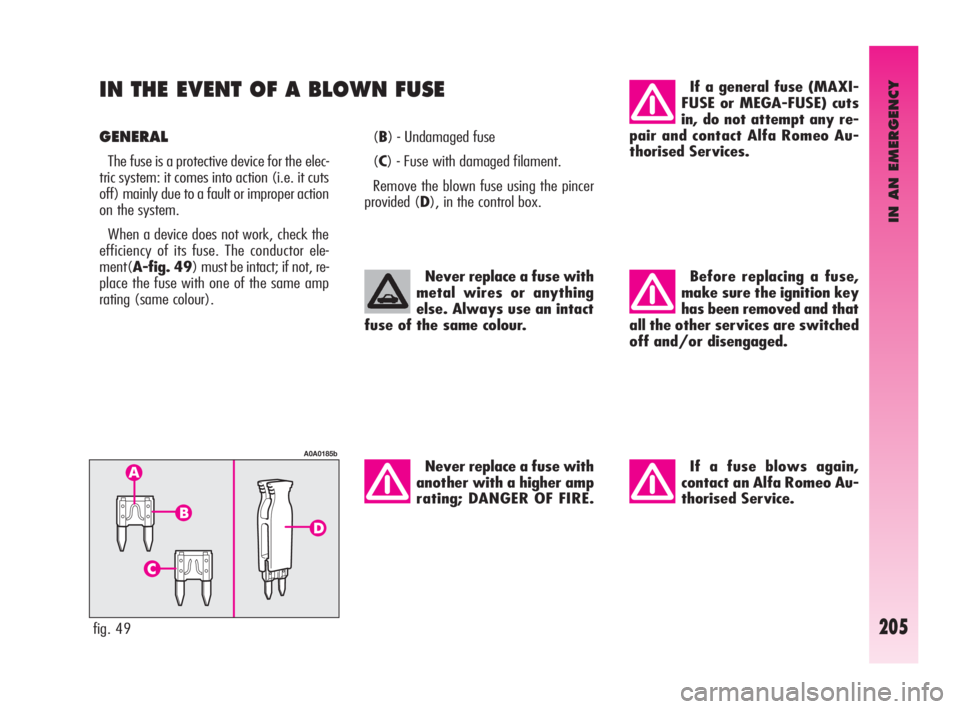
efficiency of its fuse. The conductor ele-
ment(A-fig. 49) must be intact; if not, re-
place the fuse with one of the same amp
rating (same colour).(B) - Undamaged fuse
(C) - Fuse with damaged filament.
Remove the blown fuse using the pincer
provided (D), in the control box.
fig. 49
A0A0185b
Never replace a fuse with
metal wires or anything
else. Always use an intact
fuse of the same colour.
Never replace a fuse with
another with a higher amp
rating; DANGER OF FIRE.
If a general fuse (MAXI-
FUSE or MEGA-FUSE) cuts
in, do not attempt any re-
pair and contact Alfa Romeo Au-
thorised Services.
Before replacing a fuse,
make sure the ignition key
has been removed and that
all the other services are switched
off and/or disengaged.
If a fuse blows again,
contact an Alfa Romeo Au-
thorised Service.
Page 208 of 271

IN AN EMERGENCY
206
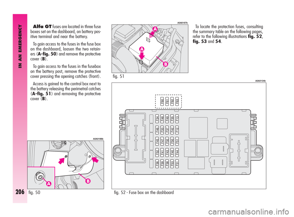
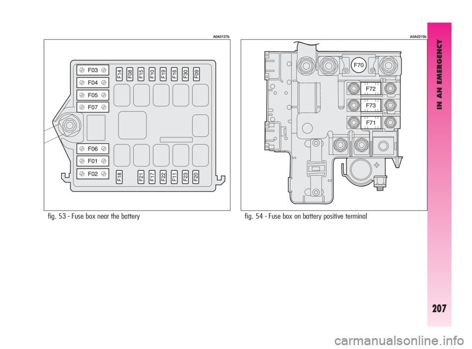
To locate the protection fuses, consulting
the summary table on the following pages,
refer to the following illustrations fig. 52,
fig. 53and54.Alfa GTfuses are located in three fuse
boxes set on the dashboard, on battery pos-
itive terminal and near the battery.
To gain access to the fuses in the fuse box
on the dashboard, loosen the two retain-
ers (A-fig. 50) and remove the protective
cover (B).
To gain access to the fuses in the fusebox
on the battery post, remove the protective
cover pressing the opening catches (front).
Access is gained to the control box next to
the battery releasing the perimetral catches
(A-fig. 51) and removing the protective
cover (B).
fig. 50
A0A0186b
fig. 51
A0A0187b
fig. 52 - Fuse box on the dashboard
A0A0134b
Page 209 of 271

IN AN EMERGENCY
207
fig. 53 - Fuse box near the battery
A0A0137b
fig. 54 - Fuse box on battery positive terminal
A0A0215b
Page 210 of 271

IN AN EMERGENCY
208
30
30
10
7.5
15
7.5
7.5 F03 (MAXI-FUSE)
F73 (MAXI-FUSE)
F13
F31
F39
F19
F31
SERVICES FIGURE FUSE AMPERES
Hazard warning lights
Right dipped-beam headlight
Left dipped-beam headlight
Right main-beam headlight
Left main-beam headlight
Foglights
Braking light
Reversing light
+30 direction indicators10
10
10
10
10
15
10
7.5
10 F53
F12
F13
F14
F15
F30
F37
F35
F53
LIGHTS FIGURE FUSE AMPERES
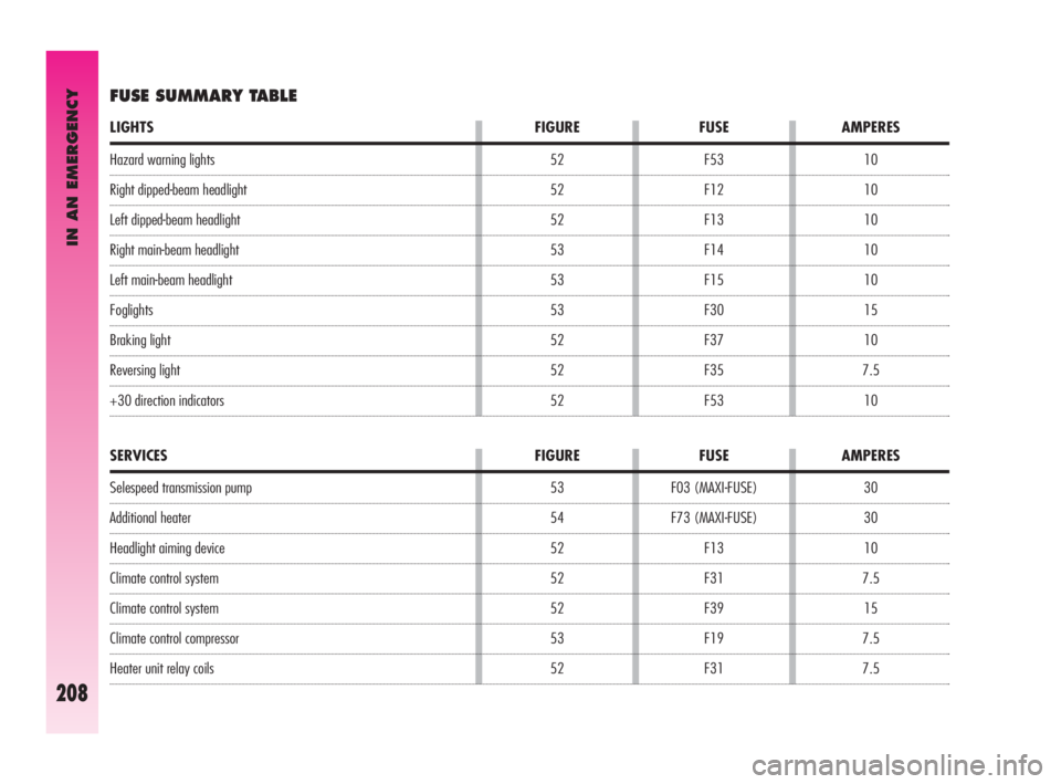
FUSE SUMMARY TABLE
Selespeed transmission pump
Additional heater
Headlight aiming device
Climate control system
Climate control system
Climate control compressor
Heater unit relay coils52
52
52
53
53
53
52
52
52
53
54
52
52
52
53
52