brake Alfa Romeo MiTo 2012 Owner handbook (in English)
[x] Cancel search | Manufacturer: ALFA ROMEO, Model Year: 2012, Model line: MiTo, Model: Alfa Romeo MiTo 2012Pages: 262, PDF Size: 6.46 MB
Page 163 of 262

162STARTING UP AND DRIVING
SNOW CHAINS
The use of snow chains should be in compliance with local regu-
lations. The snow chains may be applied only to the front wheel
tyres (drive wheels).
Check the tension of the chains after the first few metres have been
driven.
Use reduced bulk snow chains: for 195/55 R16” and 205/45
R17” tyres. Use reduced bulk snow chains with a maximum pro-
trusion from the tyres of 9 mm.
IMPORTANT The spare wheel cannot be fitted with snow chains.
If a front (drive) wheel is punctured and snow chains must be used,
you must remove a normal wheel from the rear and replace this
one with the small spare wheel. In this way, with two normal dri-
ve wheels, it is possible to use snow chains.
CAR INACTIVITY
If the car is to be left inactive for longer than a month, the following
precautions should be noted:
❍park the vehicle in a dry, covered and, if possible, ventilated
area; engage a gear and check that the handbrake is not en-
gaged;
❍disconnect the negative battery terminal and check battery
charge. Repeat this check once every three months during stor-
age;
❍clean and protect painted areas using protective wax;
❍clean and protect the shiny metal areas using special com-
mercially-available products;
❍sprinkle talcum powder on the rubber windscreen and rear win-
dow wiper blades and lift them off the glass;
❍slightly open the windows;
❍cover the car with a fabric or perforated plastic sheet. Do not
use compact plastic sheets which do not allow humidity to evap-
orate from the surface of the car.
❍inflate tyres to a pressure of +0.5 bar above the normal spec-
ified pressure and check the pressure at regular intervals;
❍if you have not disconnected the battery, check the battery
charge every thirty days;
❍do not drain the engine cooling system.
Keep your speed down when snow chains are fit-
ted. Do not exceed 50 km/h. Avoid potholes, steps
and pavements and also avoid driving long dis-
tances on roads not covered with snow to prevent dam-
aging the car and the roadbed.
Page 168 of 262
IN AN EMERGENCY167
4
JACK
Important notes:
❍the jack weight is 1.76 kg;
❍the jack requires no adjustment;
❍the jack cannot be repaired; if it breaks it must be replaced with
a new jack;
❍no tool other than the cranking device may be fitted on the
jack.Replace the wheel as follows:
❍stop the car in a position where it does not endanger on-com-
ing traffic and where you can replace the wheel safely. The
ground must be flat and compact;
❍switch off the engine, pull up the handbrake and engage 1st
gear or reverse; put on the high visibility jacket (required by
law) before leaving the vehicle;
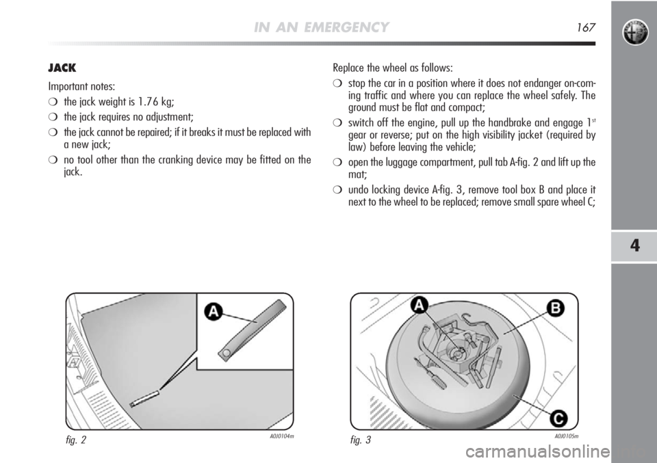
❍open the luggage compartment, pull tab A-fig. 2 and lift up the
mat;
❍undo locking device A-fig. 3, remove tool box B and place it
next to the wheel to be replaced; remove small spare wheel C;
fig. 2A0J0104mfig. 3A0J0105m
Page 176 of 262

IN AN EMERGENCY175
4
INFLATION PROCEDURE
fig. 16A0J0214m
Wear the gloves provided in the kit.
Proceed as follows:
❍Make sure the handbrake is on, unscrew the tyre valve cap,
take out the flexible filling pipe, B-fig. 16 and screw down
the ring nut C on the tyre valve;
❍make sure that switch A-fig. 17 on the compressor is in posi-
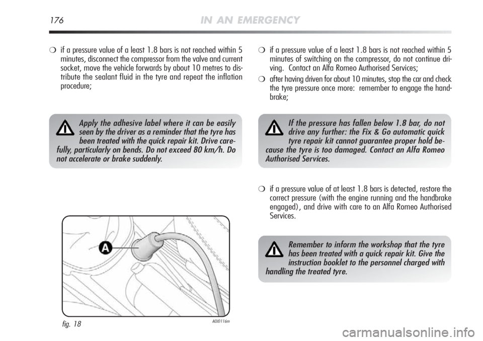
tion 0 (off), start the motor, insert pin A-fig. 18 into the cur-
rent socket/cigar lighter on the central tunnel and switch on
the compressor by placing switch A-fig. 17 in position I (on);
❍inflate the tyre to the pressure shown in the paragraph entitled
“Wheels” in chapter 6. In order to obtain a precise reading,
check the pressure on pressure gauge B-fig. 17 with the com-
pressor off;
fig. 17A0J0114m
Page 177 of 262
176IN AN EMERGENCY
❍if a pressure value of a least 1.8 bars is not reached within 5
minutes, disconnect the compressor from the valve and current
socket, move the vehicle forwards by about 10 metres to dis-
tribute the sealant fluid in the tyre and repeat the inflation
procedure;
fig. 18A0J0116m
❍if a pressure value of a least 1.8 bars is not reached within 5
minutes of switching on the compressor, do not continue dri-
ving. Contact an Alfa Romeo Authorised Services;
❍after having driven for about 10 minutes, stop the car and check
the tyre pressure once more: remember to engage the hand-
brake;
❍if a pressure value of at least 1.8 bars is detected, restore the
correct pressure (with the engine running and the handbrake
engaged), and drive with care to an Alfa Romeo Authorised
Services.
Apply the adhesive label where it can be easily
seen by the driver as a reminder that the tyre has
been treated with the quick repair kit. Drive care-
fully, particularly on bends. Do not exceed 80 km/h. Do
not accelerate or brake suddenly.If the pressure has fallen below 1.8 bar, do not
drive any further: the Fix & Go automatic quick
tyre repair kit cannot guarantee proper hold be-
cause the tyre is too damaged. Contact an Alfa Romeo
Authorised Services.
Remember to inform the workshop that the tyre
has been treated with a quick repair kit. Give the
instruction booklet to the personnel charged with
handling the treated tyre.
Page 180 of 262

5/21W
–
55W
55W
D1S
21W
21W
5W
–
–
5W
55W
21W
21W
10W
5W
5W
5WA
–
D
D
–
B
B
A
–
–
A
E
B
B
C
A
C
A
IN AN EMERGENCY179
4
W21/5W
LED
H7
H7
F
WY21W
P21W
W5W
LED
LED
W5W
H1
P21W
P21W
C10W
W5W
C5W
W5W
Bulb Type Power Ref. figure
Front side lights/Daylight lights
Rear side lights
Dipped beams
Main beams
Dipped beams/Main beams (versions with Bi-xenon
headlights) (for versions/markets, where provided)
Front direction indicators
Rear direction indicators
Side direction indicators
Brake light
3rd brake light
Number plate light
Fog lights
Rear fog lights
Reversing light
Front courtesy light
luggage compartment courtesy light
Glove compartment courtesy light
Door lights
Page 183 of 262

182IN AN EMERGENCY
Side indicators
To change the bulb, proceed as follows:
❍work on lens A-fig. 26 to compress clip B, then pull the unit
outwards;
❍turn bulb holder C anticlockwise, remove the bulb and replace
it;
❍refit the bulb holder C in the lens and turn it clockwise;
❍refit the unit, making sure that internal clip B clips into posi-
tion.
FRONT FOG LIGHTS(for versions/markets, where provided)
Contact an Alfa Romeo Authorised Services to replace these bulbs.
REAR LIGHT CLUSTERS
To access the light cluster, move the luggage compartment side
trim (see Fig. 27). These contain the bulbs for the side lights, di-
rection indicators and brake lights.
SIDE LIGHTS/BRAKE LIGHTS
These are LED lights. Contact an Alfa Romeo Authorised Services
to replace these lights.
DIRECTION INDICATORS
To replace the bulb remove bulb holder A-fig. 27.
fig. 26A0J0042mfig. 27A0J0043m
Page 184 of 262

IN AN EMERGENCY183
4
REAR FOG LIGHTS/REVERSING LIGHTS
To replace the rear fog lights A-fig. 28 or reversing lights B con-
tact an Alfa Romeo Authorised Services.
NUMBER PLATE LIGHTS
To change the bulb proceed as follows:
❍remove the lens unit A-fig. 29;
❍turn bulb holder B-fig. 30 anticlockwise, remove bulb C and re-
place it.
THIRD BRAKE LIGHTS
These are located in the tailgate and are LED lights. Contact an
Alfa Romeo Authorised Services to replace these lights.
fig. 28A0J0044mfig. 30A0J0045m
fig. 29A0J0046m
Page 193 of 262

15
7.5
7.5
15
15
15
5
5
5
192IN AN EMERGENCY
F14
F12
F13
F12
F13
F30
F37
F51
F3241
43
43
43
43
41
43
43
43
FUSE SUMMARY TABLE
LIGHTS FUSE AMPERE FIGURE
Main beams
Right hand dipped beam headlight
Left hand dipped beam headlight
Headlight gas discharge system (right side)
Headlight gas discharge system (left side)
Fog lights
3rdBrake light
Reversing light
Front courtesy light, luggage compartment light,
Sun visor courtesy light, Door lights,
Glove compartment light
Page 194 of 262
41
41
41
43
41
41
41
41
43
43
4315
20
15
7.5
30
7.5
30
15
5
10
5F08
F09
F10
F13
F15
F19
F20
F21
F31
F36
F37
IN AN EMERGENCY193
4
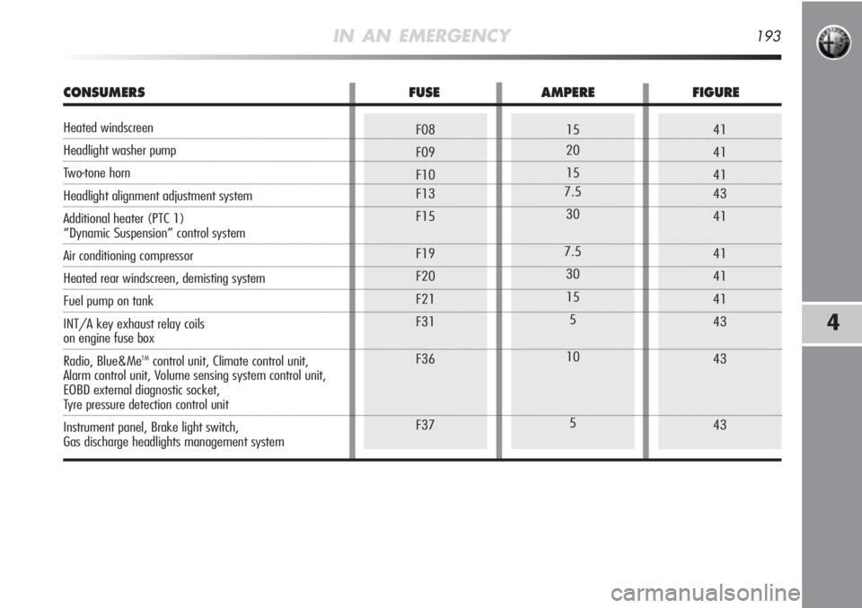
CONSUMERS FUSE AMPERE FIGURE
Heated windscreen
Headlight washer pump
Two-tone horn
Headlight alignment adjustment system
Additional heater (PTC 1)
“Dynamic Suspension” control system
Air conditioning compressor
Heated rear windscreen, demisting system
Fuel pump on tank
INT/A key exhaust relay coils
on engine fuse box
Radio, Blue&Me
TMcontrol unit, Climate control unit,
Alarm control unit, Volume sensing system control unit,
EOBD external diagnostic socket,
Tyre pressure detection control unit
Instrument panel, Brake light switch,
Gas discharge headlights management system
Page 196 of 262
43
43
45
45
45
45
45
45
41
41
415
5
15
10
15
20
–
15
40
15
7.5F51
F53
F4
F5
F6
F1
F2
F3
F83
F85
F87
IN AN EMERGENCY195
4
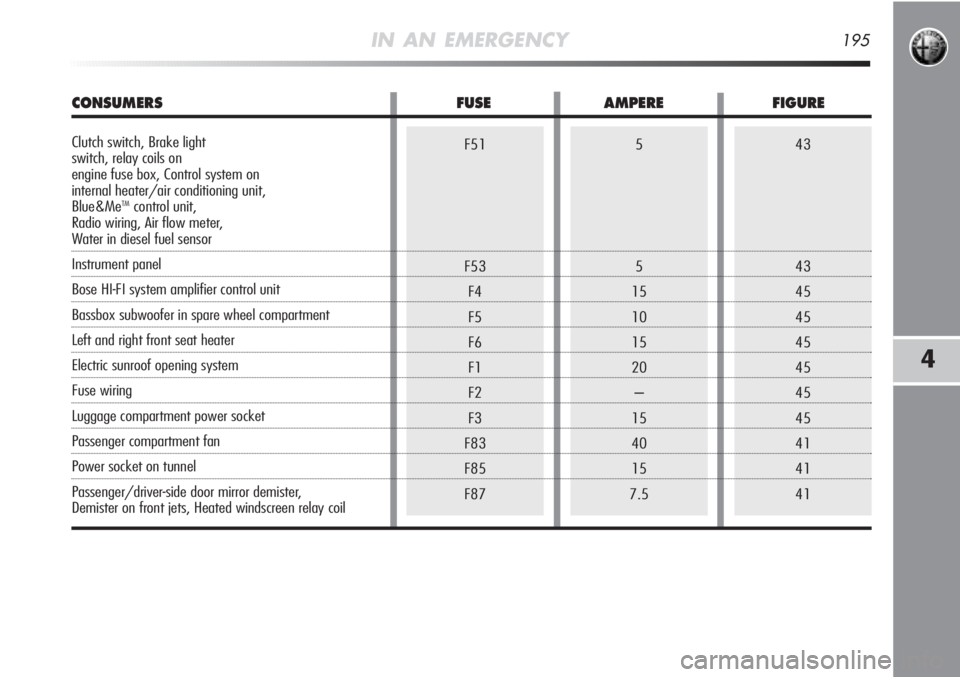
CONSUMERS FUSE AMPERE FIGURE
Clutch switch, Brake light
switch, relay coils on
engine fuse box, Control system on
internal heater/air conditioning unit,
Blue&Me
TMcontrol unit,
Radio wiring, Air flow meter,
Water in diesel fuel sensor
Instrument panel
Bose HI-FI system amplifier control unit
Bassbox subwoofer in spare wheel compartment
Left and right front seat heater
Electric sunroof opening system
Fuse wiring
Luggage compartment power socket
Passenger compartment fan
Power socket on tunnel
Passenger/driver-side door mirror demister,
Demister on front jets, Heated windscreen relay coil